EP0176121A1 - Verfahren zur Detektion und Beseitigung der von einer pyramidenförmigen Infrarotkuppel erzeugten Störbilder - Google Patents
Verfahren zur Detektion und Beseitigung der von einer pyramidenförmigen Infrarotkuppel erzeugten Störbilder Download PDFInfo
- Publication number
- EP0176121A1 EP0176121A1 EP85201327A EP85201327A EP0176121A1 EP 0176121 A1 EP0176121 A1 EP 0176121A1 EP 85201327 A EP85201327 A EP 85201327A EP 85201327 A EP85201327 A EP 85201327A EP 0176121 A1 EP0176121 A1 EP 0176121A1
- Authority
- EP
- European Patent Office
- Prior art keywords
- frame
- dome
- objective
- levels
- image
- Prior art date
- Legal status (The legal status is an assumption and is not a legal conclusion. Google has not performed a legal analysis and makes no representation as to the accuracy of the status listed.)
- Granted
Links
Images


Classifications
-
- H—ELECTRICITY
- H01—ELECTRIC ELEMENTS
- H01Q—ANTENNAS, i.e. RADIO AERIALS
- H01Q1/00—Details of, or arrangements associated with, antennas
- H01Q1/42—Housings not intimately mechanically associated with radiating elements, e.g. radome
- H01Q1/421—Means for correcting aberrations introduced by a radome
-
- F—MECHANICAL ENGINEERING; LIGHTING; HEATING; WEAPONS; BLASTING
- F41—WEAPONS
- F41G—WEAPON SIGHTS; AIMING
- F41G7/00—Direction control systems for self-propelled missiles
- F41G7/20—Direction control systems for self-propelled missiles based on continuous observation of target position
- F41G7/22—Homing guidance systems
- F41G7/2253—Passive homing systems, i.e. comprising a receiver and do not requiring an active illumination of the target
-
- F—MECHANICAL ENGINEERING; LIGHTING; HEATING; WEAPONS; BLASTING
- F41—WEAPONS
- F41G—WEAPON SIGHTS; AIMING
- F41G7/00—Direction control systems for self-propelled missiles
- F41G7/20—Direction control systems for self-propelled missiles based on continuous observation of target position
- F41G7/22—Homing guidance systems
- F41G7/2273—Homing guidance systems characterised by the type of waves
- F41G7/2293—Homing guidance systems characterised by the type of waves using electromagnetic waves other than radio waves
-
- G—PHYSICS
- G01—MEASURING; TESTING
- G01S—RADIO DIRECTION-FINDING; RADIO NAVIGATION; DETERMINING DISTANCE OR VELOCITY BY USE OF RADIO WAVES; LOCATING OR PRESENCE-DETECTING BY USE OF THE REFLECTION OR RERADIATION OF RADIO WAVES; ANALOGOUS ARRANGEMENTS USING OTHER WAVES
- G01S3/00—Direction-finders for determining the direction from which infrasonic, sonic, ultrasonic or electromagnetic waves, or particle emission, not having a directional significance, are being received
- G01S3/78—Direction-finders for determining the direction from which infrasonic, sonic, ultrasonic or electromagnetic waves, or particle emission, not having a directional significance, are being received using electromagnetic waves other than radio waves
- G01S3/782—Systems for determining direction or deviation from predetermined direction
- G01S3/785—Systems for determining direction or deviation from predetermined direction using adjustment of orientation of directivity characteristics of a detector or detector system to give a desired condition of signal derived from that detector or detector system
- G01S3/786—Systems for determining direction or deviation from predetermined direction using adjustment of orientation of directivity characteristics of a detector or detector system to give a desired condition of signal derived from that detector or detector system the desired condition being maintained automatically
Definitions
- the invention relates to an electronic device for detecting and eliminating parasitic images created by the IR pyramid dome of an infrared seeker (ADIR) for a missile not stabilized in roll,
- ADIR infrared seeker
- the signal collected in the focal plane of the objective of the seeker which can have an origin of a first type coming from a source located in the field of said objective and whose radiation is transmitted through the IR dome, or an origin of a second type coming from a source external to said field and whose radiation after transmission through a facet of the IR dome is reflected by the opposite facet.
- the source located in the Objective field can be The useful target, an element of the landscape, a decoy, etc ...
- the source outside the Objective field can be an element of the landscape (including the sun), a lure, etc.
- the solution envisaged is not an optical means, but an electronic device whose purpose is to detect and therefore eliminate these spurious images.
- This device is remarkable in that the analysis of the scene delimited by the Objective field resulting in a succession of frames of period T, the levels of the points of the frame of rank N - 1 preceding any frame of rank N are stored in a frame memory, the levels at two points corresponding to the same geographic location of the scene, one on the frame N at an instant t, the other on the frame N - 1 at the instant t - T being transmitted respectively to the non-inverting input and to the inverting input of a differential detector whose output is connected through an operator for taking an absolute value to an input of a comparator on the other input of which is applied a threshold level of positive value, the level coming from said operator indicating the appearance of a spurious image if its value is greater than said threshold value, the signal at the output of the comparator serving to inhibit the taking into account of said image parasite.
- this device is intended for a non-stabilized roll missile. It is therefore an aid for hanging in flight, re-hanging in vot and pursuit.
- the elementary duration of the treatment to a sufficiently low value (for example a frame period of 5 ms) such that it is possible to neglect in particular the displacement of the missile (3.5 m at Mach 2),
- the displacement relative target-missile The magnification of the target (less than an elementary field of 0.5 m rd for a target of diameter 2 m at the very short distance of 100 m), the images of the first type remain identical, while the images of the second type describe a trajectory during the same time.
- a complete analysis of the scene delimits the field of the seeker according to its characteristics (optical system, detectors, scanning mode).
- the image thus obtained in the focal plane of the objective constitutes a frame represented in FIG. 2.
- the infrared detectors arranged in a strip B of 32 elements translate the flux they receive in an electrical signal.
- a prism rotating at the level of the lens produces the rotation of the image in the scene plane.
- Each detector element therefore analyzes a circular crown centered in Co.
- the flux which it receives is integrated and read sequentially for a certain time according to the speed of rotation every 1/128 turn.
- One of these elements is represented around the point M of polar coordinates ⁇ and ⁇ . If the scanning speed is 200 t / s, the frame period is 5 ms.
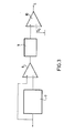
- the levels of the signals corresponding to the various picture elements on the successive frames are transmitted to the inputs of a differential detector 8, by direct route on the non-inverting input and through a memory 7 on the inverting input.
- the memory 7, called frame memory is equivalent to a delay line of length equal to The duration of a frame period T.
- the comparator output provides a logic signal L.
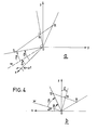
- the facet plane of reflection is defined by two lines the axis y'Oy and the line 0w, intersection of the plane x0z with a plane parallel to the facet of the IR dome on which the radiation coming from the spurious source is reflected.
- the line Ow makes an angle ⁇ with the axis x'Ox.
- the direction of the incident beam is given by the straight line 0S which makes an angle ⁇ with the facet in the plane xOz.
- Figure 4b shows the above definitions in the xOz plane at the initial time.
- the center 0 of the Oxyz fixed frame of reference is positioned at the center of the seeker optical system.
- this optical system is represented in a simplified manner by a lens 11 located in The body of the missile 12 adjoining the IR pyramid dome 1.
- C o being The center of the field in the image focal plane PF at the distance F from the center 0 of the frame of reference, we assume to fix The ideas that At the initial instant, The image is on the vertical axis C o Y of symmetry of said plane, the horizontal axis C o X being parallel to Oy (see also Figure 2).
- the vector C o R has as components:
- the corresponding frames result from the sampling of these trajectories by the array of infrared detectors animated by a "polar type" scanning movement.
- the focal plane is defined as the plane perpendicular to the line of sight represented in figure 7 and given by its site Y (counted positively upwards) and its azimuth ⁇ (counted in the trigonometric direction in the horizontal plane) and such that the point C o (center of the field) is at the di.stance F of Origin 0.
- the vector C o R has as components:
Landscapes
- Engineering & Computer Science (AREA)
- Physics & Mathematics (AREA)
- Chemical & Material Sciences (AREA)
- Combustion & Propulsion (AREA)
- General Engineering & Computer Science (AREA)
- Electromagnetism (AREA)
- General Physics & Mathematics (AREA)
- Radar, Positioning & Navigation (AREA)
- Remote Sensing (AREA)
- Closed-Circuit Television Systems (AREA)
- Aiming, Guidance, Guns With A Light Source, Armor, Camouflage, And Targets (AREA)
Applications Claiming Priority (2)
| Application Number | Priority Date | Filing Date | Title |
|---|---|---|---|
| FR8413285A FR2569926B1 (fr) | 1984-08-28 | 1984-08-28 | Dispositif de detection et d'elimination d'images parasites creees par un ir dome pyramidal |
| FR8413285 | 1984-08-28 |
Publications (2)
| Publication Number | Publication Date |
|---|---|
| EP0176121A1 true EP0176121A1 (de) | 1986-04-02 |
| EP0176121B1 EP0176121B1 (de) | 1990-02-14 |
Family
ID=9307243
Family Applications (1)
| Application Number | Title | Priority Date | Filing Date |
|---|---|---|---|
| EP85201327A Expired - Lifetime EP0176121B1 (de) | 1984-08-28 | 1985-08-19 | Verfahren zur Detektion und Beseitigung der von einer pyramidenförmigen Infrarotkuppel erzeugten Störbilder |
Country Status (4)
| Country | Link |
|---|---|
| US (1) | US4681282A (de) |
| EP (1) | EP0176121B1 (de) |
| DE (1) | DE3576050D1 (de) |
| FR (1) | FR2569926B1 (de) |
Cited By (1)
| Publication number | Priority date | Publication date | Assignee | Title |
|---|---|---|---|---|
| FR2607917A1 (fr) * | 1986-12-08 | 1988-06-10 | Roche Kerandraon Oliver | Guidage par infrarouge simplifie pour tout projectile |
Citations (6)
| Publication number | Priority date | Publication date | Assignee | Title |
|---|---|---|---|---|
| US3445663A (en) * | 1964-06-25 | 1969-05-20 | Hughes Aircraft Co | Noise discrimination by unblanking during the time that an a-c reference signal is in the neighborhood of the value it had at the time of the previously accepted pulse |
| US3535527A (en) * | 1968-04-26 | 1970-10-20 | North American Rockwell | Digital correlation pattern tracker with single axis scanning |
| US3940767A (en) * | 1955-01-21 | 1976-02-24 | Hughes Aircraft Company | Electronic radome-error compensation system |
| FR2405562A1 (fr) * | 1977-10-06 | 1979-05-04 | Messerschmitt Boelkow Blohm | Procede d'elimination de l'erreur introduite par des radomes entourant les antennes electromagnetiques, et dispositif pour la mise en oeuvre du procede |
| GB1594602A (en) * | 1975-06-04 | 1981-08-05 | Marconi Co Ltd | Radio systems and apparatus |
| GB2071957A (en) * | 1980-02-14 | 1981-09-23 | Messerschmitt Boelkow Blohm | Panoramic locating apparatus |
Family Cites Families (3)
| Publication number | Priority date | Publication date | Assignee | Title |
|---|---|---|---|---|
| US3064924A (en) * | 1956-02-27 | 1962-11-20 | North American Aviation Inc | Infrared terminal guidance tracking system |
| GB1005820A (en) * | 1958-07-01 | 1965-09-29 | Dehavilland Aircraft | Improvements in guided missiles |
| US4244540A (en) * | 1978-09-21 | 1981-01-13 | The United States Of America As Represented By The Secretary Of The Navy | Spectral discrimination system for an optical seeker |
-
1984
- 1984-08-28 FR FR8413285A patent/FR2569926B1/fr not_active Expired
-
1985
- 1985-08-19 DE DE8585201327T patent/DE3576050D1/de not_active Expired - Lifetime
- 1985-08-19 EP EP85201327A patent/EP0176121B1/de not_active Expired - Lifetime
- 1985-08-28 US US06/770,339 patent/US4681282A/en not_active Expired - Fee Related
Patent Citations (6)
| Publication number | Priority date | Publication date | Assignee | Title |
|---|---|---|---|---|
| US3940767A (en) * | 1955-01-21 | 1976-02-24 | Hughes Aircraft Company | Electronic radome-error compensation system |
| US3445663A (en) * | 1964-06-25 | 1969-05-20 | Hughes Aircraft Co | Noise discrimination by unblanking during the time that an a-c reference signal is in the neighborhood of the value it had at the time of the previously accepted pulse |
| US3535527A (en) * | 1968-04-26 | 1970-10-20 | North American Rockwell | Digital correlation pattern tracker with single axis scanning |
| GB1594602A (en) * | 1975-06-04 | 1981-08-05 | Marconi Co Ltd | Radio systems and apparatus |
| FR2405562A1 (fr) * | 1977-10-06 | 1979-05-04 | Messerschmitt Boelkow Blohm | Procede d'elimination de l'erreur introduite par des radomes entourant les antennes electromagnetiques, et dispositif pour la mise en oeuvre du procede |
| GB2071957A (en) * | 1980-02-14 | 1981-09-23 | Messerschmitt Boelkow Blohm | Panoramic locating apparatus |
Cited By (2)
| Publication number | Priority date | Publication date | Assignee | Title |
|---|---|---|---|---|
| FR2607917A1 (fr) * | 1986-12-08 | 1988-06-10 | Roche Kerandraon Oliver | Guidage par infrarouge simplifie pour tout projectile |
| WO1988004400A1 (fr) * | 1986-12-08 | 1988-06-16 | Bernard Baudrous | Guidage par infra-rouge simplifie pour tout projectile |
Also Published As
| Publication number | Publication date |
|---|---|
| US4681282A (en) | 1987-07-21 |
| DE3576050D1 (de) | 1990-03-22 |
| FR2569926A1 (fr) | 1986-03-07 |
| FR2569926B1 (fr) | 1986-09-05 |
| EP0176121B1 (de) | 1990-02-14 |
Similar Documents
| Publication | Publication Date | Title |
|---|---|---|
| FR2638544A1 (fr) | Systeme pour determiner la position spatiale d'un objet en mouvement, applique notamment a l'atterrissage des avions | |
| FR2651079A1 (fr) | Dispositif de transmission d'images en temps reel, a partir d'un engin volant guide | |
| FR2595817A1 (fr) | Procede de determination de l'orientation d'une plate-forme de capteur imageur ou instrument analogue | |
| DE102006031114A1 (de) | 3D Kombinationsmessgerät aus digitaler Kamera und Laserscanner | |
| EP0790505A1 (de) | Schlitz-Sonnensensor | |
| EP0778958B1 (de) | Vorrichtung zum ausrichten eines beobachtungsinstrumentes | |
| US20030184763A1 (en) | Spherical form measuring and analyzing method | |
| US6479808B1 (en) | Method and systems for collecting data from multiple fields of view | |
| EP3070643B1 (de) | Verfahren und system zur objekterkennung durch analyse von signalen eines numerischen bildes einer szene | |
| EP0341142A2 (de) | Beobachtungsvorrichtung durch Abtastung eines Raumkörpers und Messung der Winkelgeschwindigkeit eines Raumfahrzeuges, Beobachtungssystem für seine Anwendung und Raumfahrzeug mit diesem System | |
| EP0196980B1 (de) | Visiersystem zur optischen Entfernungsmessung | |
| EP0176121B1 (de) | Verfahren zur Detektion und Beseitigung der von einer pyramidenförmigen Infrarotkuppel erzeugten Störbilder | |
| FR2724464A1 (fr) | Dispositif embarquable de mesure de retrodiffusion de lumiere | |
| EP0064439A1 (de) | Kartographischer Anweiser mit photographischer Registrierung | |
| FR2792488A1 (fr) | Dispositif d'emission d'images video numeriques | |
| EP0508905B1 (de) | Verfahren zur Selbstlenkung eines Flugkörpers gegen ein Ziel mittels Entfernungsmessungen | |
| EP0436429B1 (de) | Abtastvorrichtung und ihre Anwendung in Analysevorrichtungen | |
| FR2709557A1 (fr) | Dispositif optique de mesure à distance des variations d'orientation d'un objet. | |
| EP2811319A1 (de) | Optisches System zur Richtungs- und Positionsmessung mit Punktquelle, zentraler Maske, fotoempfindlichem Matrixsensor und Tripelspiegelreflektor | |
| EP3489152A2 (de) | Beobachtungsinstrument mit einem spiegel-autokollimator, der an einem sternsucher montiert ist | |
| US10070080B2 (en) | Multi-directional, multi-spectral star tracker with a common aperture and common camera | |
| EP0071492A1 (de) | Gerät zur panoramaoptischen Überwachung | |
| FR2687791A1 (fr) | Systeme optronique de poursuite tridimensionnelle avec alignement automatique d'un telemetre optique sur la cible. | |
| FR2481794A1 (fr) | Dispositif optique d'analyse d'un champ spatial et de localisation angulaire d'un objet rayonnant dans ce champ | |
| FR3051920A1 (fr) | Drone adapte a la vision d'une scene eloignee |
Legal Events
| Date | Code | Title | Description |
|---|---|---|---|
| PUAI | Public reference made under article 153(3) epc to a published international application that has entered the european phase |
Free format text: ORIGINAL CODE: 0009012 |
|
| AK | Designated contracting states |
Kind code of ref document: A1 Designated state(s): BE DE FR GB IT NL SE |
|
| 17P | Request for examination filed |
Effective date: 19860924 |
|
| 17Q | First examination report despatched |
Effective date: 19880628 |
|
| GRAA | (expected) grant |
Free format text: ORIGINAL CODE: 0009210 |
|
| AK | Designated contracting states |
Kind code of ref document: B1 Designated state(s): BE DE FR GB IT NL SE |
|
| REF | Corresponds to: |
Ref document number: 3576050 Country of ref document: DE Date of ref document: 19900322 |
|
| ITF | It: translation for a ep patent filed | ||
| GBT | Gb: translation of ep patent filed (gb section 77(6)(a)/1977) | ||
| PLBE | No opposition filed within time limit |
Free format text: ORIGINAL CODE: 0009261 |
|
| STAA | Information on the status of an ep patent application or granted ep patent |
Free format text: STATUS: NO OPPOSITION FILED WITHIN TIME LIMIT |
|
| 26N | No opposition filed | ||
| PGFP | Annual fee paid to national office [announced via postgrant information from national office to epo] |
Ref country code: BE Payment date: 19920813 Year of fee payment: 8 |
|
| PGFP | Annual fee paid to national office [announced via postgrant information from national office to epo] |
Ref country code: SE Payment date: 19920827 Year of fee payment: 8 |
|
| PGFP | Annual fee paid to national office [announced via postgrant information from national office to epo] |
Ref country code: NL Payment date: 19920831 Year of fee payment: 8 |
|
| PG25 | Lapsed in a contracting state [announced via postgrant information from national office to epo] |
Ref country code: SE Effective date: 19930820 |
|
| ITTA | It: last paid annual fee | ||
| PG25 | Lapsed in a contracting state [announced via postgrant information from national office to epo] |
Ref country code: BE Effective date: 19930831 |
|
| REG | Reference to a national code |
Ref country code: GB Ref legal event code: 732E |
|
| ITPR | It: changes in ownership of a european patent |
Owner name: CESSIONE;THOMSON - TRT DEFENSE |
|
| BERE | Be: lapsed |
Owner name: TELECOMMUNICATIONS RADIOELECTRIQUES ET TELEPHONIQU Effective date: 19930831 |
|
| PG25 | Lapsed in a contracting state [announced via postgrant information from national office to epo] |
Ref country code: NL Effective date: 19940301 |
|
| NLV4 | Nl: lapsed or anulled due to non-payment of the annual fee | ||
| EUG | Se: european patent has lapsed |
Ref document number: 85201327.5 Effective date: 19940310 |
|
| PGFP | Annual fee paid to national office [announced via postgrant information from national office to epo] |
Ref country code: GB Payment date: 19950719 Year of fee payment: 11 |
|
| PGFP | Annual fee paid to national office [announced via postgrant information from national office to epo] |
Ref country code: DE Payment date: 19950721 Year of fee payment: 11 |
|
| PGFP | Annual fee paid to national office [announced via postgrant information from national office to epo] |
Ref country code: FR Payment date: 19950811 Year of fee payment: 11 |
|
| PG25 | Lapsed in a contracting state [announced via postgrant information from national office to epo] |
Ref country code: GB Effective date: 19960819 |
|
| GBPC | Gb: european patent ceased through non-payment of renewal fee |
Effective date: 19960819 |
|
| PG25 | Lapsed in a contracting state [announced via postgrant information from national office to epo] |
Ref country code: FR Effective date: 19970430 |
|
| PG25 | Lapsed in a contracting state [announced via postgrant information from national office to epo] |
Ref country code: DE Effective date: 19970501 |
|
| REG | Reference to a national code |
Ref country code: FR Ref legal event code: ST |