EP0176233A1 - Couvre-joint tubulaire - Google Patents
Couvre-joint tubulaire Download PDFInfo
- Publication number
- EP0176233A1 EP0176233A1 EP19850305992 EP85305992A EP0176233A1 EP 0176233 A1 EP0176233 A1 EP 0176233A1 EP 19850305992 EP19850305992 EP 19850305992 EP 85305992 A EP85305992 A EP 85305992A EP 0176233 A1 EP0176233 A1 EP 0176233A1
- Authority
- EP
- European Patent Office
- Prior art keywords
- sleeve
- pipe
- service
- accordance
- cut
- Prior art date
- Legal status (The legal status is an assumption and is not a legal conclusion. Google has not performed a legal analysis and makes no representation as to the accuracy of the status listed.)
- Withdrawn
Links
- 239000000463 material Substances 0.000 claims abstract description 24
- 229910052751 metal Inorganic materials 0.000 claims abstract description 10
- 239000002184 metal Substances 0.000 claims abstract description 10
- 239000000853 adhesive Substances 0.000 claims description 3
- 230000001070 adhesive effect Effects 0.000 claims description 3
- 239000002904 solvent Substances 0.000 claims description 2
- XLYOFNOQVPJJNP-UHFFFAOYSA-N water Substances O XLYOFNOQVPJJNP-UHFFFAOYSA-N 0.000 claims description 2
- 229910010293 ceramic material Inorganic materials 0.000 claims 1
- 238000009434 installation Methods 0.000 description 6
- XEEYBQQBJWHFJM-UHFFFAOYSA-N Iron Chemical compound [Fe] XEEYBQQBJWHFJM-UHFFFAOYSA-N 0.000 description 2
- 230000006835 compression Effects 0.000 description 2
- 238000007906 compression Methods 0.000 description 2
- 210000002268 wool Anatomy 0.000 description 2
- RYGMFSIKBFXOCR-UHFFFAOYSA-N Copper Chemical compound [Cu] RYGMFSIKBFXOCR-UHFFFAOYSA-N 0.000 description 1
- 239000004411 aluminium Substances 0.000 description 1
- 229910052782 aluminium Inorganic materials 0.000 description 1
- XAGFODPZIPBFFR-UHFFFAOYSA-N aluminium Chemical compound [Al] XAGFODPZIPBFFR-UHFFFAOYSA-N 0.000 description 1
- 239000010425 asbestos Substances 0.000 description 1
- 239000004568 cement Substances 0.000 description 1
- 239000000919 ceramic Substances 0.000 description 1
- 238000010276 construction Methods 0.000 description 1
- 229910052802 copper Inorganic materials 0.000 description 1
- 239000010949 copper Substances 0.000 description 1
- 239000000835 fiber Substances 0.000 description 1
- 239000011152 fibreglass Substances 0.000 description 1
- 229910052742 iron Inorganic materials 0.000 description 1
- 239000007788 liquid Substances 0.000 description 1
- 238000004519 manufacturing process Methods 0.000 description 1
- 238000000034 method Methods 0.000 description 1
- 239000011490 mineral wool Substances 0.000 description 1
- 229910052895 riebeckite Inorganic materials 0.000 description 1
- 229910001220 stainless steel Inorganic materials 0.000 description 1
- 239000010935 stainless steel Substances 0.000 description 1
Images
Classifications
-
- F—MECHANICAL ENGINEERING; LIGHTING; HEATING; WEAPONS; BLASTING
- F16—ENGINEERING ELEMENTS AND UNITS; GENERAL MEASURES FOR PRODUCING AND MAINTAINING EFFECTIVE FUNCTIONING OF MACHINES OR INSTALLATIONS; THERMAL INSULATION IN GENERAL
- F16L—PIPES; JOINTS OR FITTINGS FOR PIPES; SUPPORTS FOR PIPES, CABLES OR PROTECTIVE TUBING; MEANS FOR THERMAL INSULATION IN GENERAL
- F16L5/00—Devices for use where pipes, cables or protective tubing pass through walls or partitions
-
- E—FIXED CONSTRUCTIONS
- E04—BUILDING
- E04D—ROOF COVERINGS; SKY-LIGHTS; GUTTERS; ROOF-WORKING TOOLS
- E04D13/00—Special arrangements or devices in connection with roof coverings; Protection against birds; Roof drainage ; Sky-lights
- E04D13/14—Junctions of roof sheathings to chimneys or other parts extending above the roof
Definitions
- the present invention relates to sleeves which facilitate stopping of the area between a pipe or other service and a surrounding floor, wall or roof.
- wall where hereafter used shall mean a wall, floor, ceiling, roof or the like.
- stopping materials may provide an adequate fire rating however it is necessary that they are compressed to a predetermined extent and furthermore it is desirable that the stopping entirely fills the area between the pipe and the sleeve. It is difficult if not impossible when pushing stopping material into the area between the pipe and the sleeve to ensure that the material is uniformly compressed to a specified degree and it is likewise difficult to ensure that no voids or gaps occur in the stopping.
- a pipe or like service sleeve comprising a metal sleeve formed as an open ended cylinder and having a full length longitudinal cut therein; stopping material disposed around the internal surface of the sleeve and adapted, when the longitudinally cut portion of the sleeve is joined in a predetermined position around a pipe or like service of predetermined dimensions to uniformly fill the cavity between the metal sleeve and the pipe or like service.
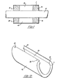
- Figure 1 depicts a conventional metal sleeve 1 in place around a pipe 2 although the wall which would normally surround the sleeve 1 is not shown. It may be seen that in accordance with known methods stopping material 3 has been inserted in the cavity 4 between the pipe 2 and the sleeve 1. It may furthermore be seen however that the stopping material 3 does not penetrate into the inaccessible portions of the cavity 5 and consequently the fire rating of a wall incorporating the sleeve or indeed the acoustic qualities of the wall may not be up to the standard required. The limited access provided by the annular aperture at either end of the sleeve additionally makes it difficult to ensure that the stopping material 3 is adequately compressed in all localities.
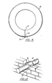
- FIGS 2, 3 and 4 depict a sleeve in accordance with the present invention comprising a metal sleeve 6 having stopping material 7 uniformly disposed around the inner surface thereof.
- This stopping material in this instance is a ceramic fibre such as "kao wool” TM having high insulating qualities and being non-flammable.
- Other known stopping materials however such as asbestos, rockwool fibreglass or similar materials may be utilised.
- the stopping material which may be supplied in the form of a blanket, is fixed onto the internal surface of the sleeve so as to prevent dislodgment and misalignment during installation.
- "liquid nails" TM adhesive has been found appropriate although many other solvent or water based non-flammable adhesives or other fixing means such as staples may be appropriate.
- the calibrating means in this instance merely comprises holes on either side of the longitudinal slit which-when superimposed upon each other may be utilised to secure the sleeve into a permanent closed circular section as depicted in Figure 3 by means of a rivet 10 or like fastening.
- the stopping material be trimmed during manufacture adjacent the longitudinal cut in the sleeve such that bunching or gaps in the stopping material will not occur when the sleeve is closed to the predetermined specifications.
- the sheet from which the sleeve 6 is fabricated may be of any suitable metal; for example galvanized iron, copper, aluminium, stainless steel etc.
- the gauge of the metal should however be such that during installation it may be expanded to be placed around a pipe and subsequently readily closed to the relevant markings by the installer. It has been found that when a galvanized sleeve is utilised gauges between 14 and 26 are appropriate.
- the present invention may save much time in the construction of a building and result in sleeves with more reliable fire and acoustic ratings.
- the sleeve may even for example be placed around a pipe prior to a bricklayer forming a wall around the sleeve and in such instances the sleeve will be maintained around the pipe in the desired concentric manner until bricked in as depicted in Figure 4. In vertical installations the sleeve may furthermore remain in the desired location until formed into a structure.
Landscapes
- Engineering & Computer Science (AREA)
- General Engineering & Computer Science (AREA)
- Architecture (AREA)
- Civil Engineering (AREA)
- Structural Engineering (AREA)
- Mechanical Engineering (AREA)
- Building Environments (AREA)
Applications Claiming Priority (3)
| Application Number | Priority Date | Filing Date | Title |
|---|---|---|---|
| AU6715/84 | 1984-08-22 | ||
| AUPG671584 | 1984-08-22 | ||
| AU46563/85A AU583050B2 (en) | 1984-08-22 | 1985-08-22 | Pipe sleeve |
Publications (1)
| Publication Number | Publication Date |
|---|---|
| EP0176233A1 true EP0176233A1 (fr) | 1986-04-02 |
Family
ID=25627601
Family Applications (1)
| Application Number | Title | Priority Date | Filing Date |
|---|---|---|---|
| EP19850305992 Withdrawn EP0176233A1 (fr) | 1984-08-22 | 1985-08-22 | Couvre-joint tubulaire |
Country Status (1)
| Country | Link |
|---|---|
| EP (1) | EP0176233A1 (fr) |
Cited By (2)
| Publication number | Priority date | Publication date | Assignee | Title |
|---|---|---|---|---|
| US20190017257A1 (en) * | 2017-07-17 | 2019-01-17 | Gabe Coscarella | Weather barrier for a building penetration with a removable collar |
| DE102018201419A1 (de) | 2018-01-30 | 2019-08-01 | Deckel Maho Pfronten Gmbh | Werkzeugmaschine |
Citations (6)
| Publication number | Priority date | Publication date | Assignee | Title |
|---|---|---|---|---|
| US690350A (en) * | 1901-08-31 | 1901-12-31 | Thomas P Bolger | Roof collar or flange. |
| US2054308A (en) * | 1934-10-09 | 1936-09-15 | Willis M Fabry | Sealing collar |
| DE2900924A1 (de) * | 1979-01-11 | 1980-07-24 | Otto Krebes | Nicht-brennbare kunststoff-isolierschale |
| US4219173A (en) * | 1977-10-05 | 1980-08-26 | Forbes George A | Insulated pipe supports |
| DE2928165A1 (de) * | 1979-07-12 | 1981-01-29 | Steffens & Co | Vorgeformte leitungsisolation |
| GB2077382A (en) * | 1980-06-04 | 1981-12-16 | Stuart Anthony Rowland | Fire-resistant sleeves |
-
1985
- 1985-08-22 EP EP19850305992 patent/EP0176233A1/fr not_active Withdrawn
Patent Citations (6)
| Publication number | Priority date | Publication date | Assignee | Title |
|---|---|---|---|---|
| US690350A (en) * | 1901-08-31 | 1901-12-31 | Thomas P Bolger | Roof collar or flange. |
| US2054308A (en) * | 1934-10-09 | 1936-09-15 | Willis M Fabry | Sealing collar |
| US4219173A (en) * | 1977-10-05 | 1980-08-26 | Forbes George A | Insulated pipe supports |
| DE2900924A1 (de) * | 1979-01-11 | 1980-07-24 | Otto Krebes | Nicht-brennbare kunststoff-isolierschale |
| DE2928165A1 (de) * | 1979-07-12 | 1981-01-29 | Steffens & Co | Vorgeformte leitungsisolation |
| GB2077382A (en) * | 1980-06-04 | 1981-12-16 | Stuart Anthony Rowland | Fire-resistant sleeves |
Cited By (4)
| Publication number | Priority date | Publication date | Assignee | Title |
|---|---|---|---|---|
| US20190017257A1 (en) * | 2017-07-17 | 2019-01-17 | Gabe Coscarella | Weather barrier for a building penetration with a removable collar |
| US10787804B2 (en) * | 2017-07-17 | 2020-09-29 | Gabe Coscarella | Weather barrier for a building penetration with a removable collar |
| DE102018201419A1 (de) | 2018-01-30 | 2019-08-01 | Deckel Maho Pfronten Gmbh | Werkzeugmaschine |
| WO2019149761A1 (fr) | 2018-01-30 | 2019-08-08 | Deckel Maho Pfronten Gmbh | Machine-outil |
Similar Documents
| Publication | Publication Date | Title |
|---|---|---|
| US6176052B1 (en) | Fire retarding division penetrating member | |
| US5887395A (en) | Firestop sleeve | |
| US4130977A (en) | Concrete insert | |
| US4922680A (en) | Systems and methods for connecting masonry veneer to structural support substrates | |
| US7775006B2 (en) | Fire stop system for wallboard and metal fluted deck construction | |
| US5351455A (en) | Method and apparatus for wallboard attachment | |
| EP3130721A1 (fr) | Élément de construction de rénovation multicouche | |
| EP4073409B1 (fr) | Conduit de ventilation ignifugé et procédé de fabrication et d'installation d'un tel conduit de ventilation | |
| EP0791995B1 (fr) | Dispositif de retenue pour ensemble de connexion électrique à pousser à travers une cloison | |
| EP0176233A1 (fr) | Couvre-joint tubulaire | |
| WO2018176077A1 (fr) | Éléments de fixation et ensembles de paroi | |
| GB2108614A (en) | Fire-seal for pipe or duct extending through wall, floor or ceiling | |
| EP3280018A1 (fr) | Boîte d'installation électrique avec insert de matériau ignifuge | |
| EP0839239B1 (fr) | Dispositif pour fixer un element formant paroi sur une structure de support | |
| US20140318064A1 (en) | Press-on retainer for fire-stopping sleeve | |
| AU726578B2 (en) | Seal for fire dampers | |
| GB2560812A (en) | Improved insulated building section | |
| CA1124099A (fr) | Manchon de cimentation sur traversee | |
| JP2005171752A (ja) | 建物外壁の改修方法及び建物外壁用胴縁支持部材 | |
| AU603845B2 (en) | Fire-resisting panel assembly and brackets therefor | |
| JP7770957B2 (ja) | 配管貫通部の雨仕舞い構造およびその施工方法 | |
| FI130394B (fi) | Parvekekaivo, rakennusosa ja parvekkeen vedenpoistojärjestelmä | |
| EP4660500A1 (fr) | Élément ignifuge et procédé d'alimentation d'un élément de conduite à travers un élément de construction | |
| JPH04207918A (ja) | 断熱被覆銅管と付随制御ケーブル貫通部の施工方法 | |
| EP3724545B1 (fr) | Un système constitué d'un scellement anti-incendie et ouverture dans le plancher ou le plafond d'un bâtiment et un procédé pour sceller une ouverture dans le plancher ou le plafond d'un bâtiment |
Legal Events
| Date | Code | Title | Description |
|---|---|---|---|
| PUAI | Public reference made under article 153(3) epc to a published international application that has entered the european phase |
Free format text: ORIGINAL CODE: 0009012 |
|
| AK | Designated contracting states |
Kind code of ref document: A1 Designated state(s): AT BE CH DE FR GB IT LI LU NL SE |
|
| 17P | Request for examination filed |
Effective date: 19860718 |
|
| RAP1 | Party data changed (applicant data changed or rights of an application transferred) |
Owner name: BRUTTFILE PTY. LIMITED |
|
| 17Q | First examination report despatched |
Effective date: 19870914 |
|
| STAA | Information on the status of an ep patent application or granted ep patent |
Free format text: STATUS: THE APPLICATION IS DEEMED TO BE WITHDRAWN |
|
| 18D | Application deemed to be withdrawn |
Effective date: 19880325 |
|
| RIN1 | Information on inventor provided before grant (corrected) |
Inventor name: O'SHEA, DIANE CHERYL |