EP0176302A1 - Vorrichtung zum Umhüllen von Gegenständen - Google Patents
Vorrichtung zum Umhüllen von Gegenständen Download PDFInfo
- Publication number
- EP0176302A1 EP0176302A1 EP85306576A EP85306576A EP0176302A1 EP 0176302 A1 EP0176302 A1 EP 0176302A1 EP 85306576 A EP85306576 A EP 85306576A EP 85306576 A EP85306576 A EP 85306576A EP 0176302 A1 EP0176302 A1 EP 0176302A1
- Authority
- EP
- European Patent Office
- Prior art keywords
- supporting head
- wire
- article
- head
- sleeve
- Prior art date
- Legal status (The legal status is an assumption and is not a legal conclusion. Google has not performed a legal analysis and makes no representation as to the accuracy of the status listed.)
- Granted
Links
Images

Classifications
-
- B—PERFORMING OPERATIONS; TRANSPORTING
- B65—CONVEYING; PACKING; STORING; HANDLING THIN OR FILAMENTARY MATERIAL
- B65B—MACHINES, APPARATUS OR DEVICES FOR, OR METHODS OF, PACKAGING ARTICLES OR MATERIALS; UNPACKING
- B65B11/00—Wrapping, e.g. partially or wholly enclosing, articles or quantities of material, in strips, sheets or blanks, of flexible material
- B65B11/06—Wrapping articles, or quantities of material, by conveying wrapper and contents in common defined paths
- B65B11/08—Wrapping articles, or quantities of material, by conveying wrapper and contents in common defined paths in a single straight path
- B65B11/10—Wrapping articles, or quantities of material, by conveying wrapper and contents in common defined paths in a single straight path to fold the wrappers in tubular form about contents
-
- B—PERFORMING OPERATIONS; TRANSPORTING
- B65—CONVEYING; PACKING; STORING; HANDLING THIN OR FILAMENTARY MATERIAL
- B65C—LABELLING OR TAGGING MACHINES, APPARATUS, OR PROCESSES
- B65C3/00—Labelling other than flat surfaces
- B65C3/02—Affixing labels to elongated objects, e.g. wires, cables, bars, tubes
Definitions
- This invention relates to apparatus for enwrapping articles and more particularly but not exclusively to apparatus for applying a sleeve of material to an elongate object.
- the wires carry a suitable form of coding.
- the coding may consist of, for example, a marked or coloured sleeve wrapped around the wire.
- apparatus for enwrapping articles comprises a supporting head adapted to carry a length of material, locating means for locating the article adjacent to the supporting head, the locating means and the supporting head being relatively movable to a position in which the material is wrapped partially around the article, the supporting head being provided with relatively movable urging members for urging the material the remaining distance around the article, there being provided securing means for securing the material in the form of a sleeve around the article.
- the article is preferably elongate and may, for example, be a length of wire.
- the length of material is preferably a plastics strip.
- the supporting head and the locating means are relatively movable to a position in which the supporting head straddles the wire and the plastics strip is wrapped around the wire through substantially 180°.
- the movable urging members may include welding electrodes whereby after the plastics strip is urged the remaining distance around the wire, the strip is welded to form a sleeve.
- the apparatus preferably includes a cutting member for separating the formed sleeve from the plastics strip.
- the cutting member may be included in the supporting head and may operate either simultaneously with the welding electrodes or subsequent to the welding operation.
- the wire is adapted to be partially enwrapped with plastics strip after relative movement between the supporting head and the locating means into a first position and after movement back to the original position, the supporting head being provided with a continuous feed of plastics strip and the wire being movable axially relative to the supporting head, the supporting head being provided with addditional movable urging members and electrodes and an additional cutting member whereby a sleeve is formed on the wire after each relative movement between the supporting head and the locating means.
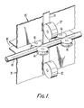
- Figure 1 is shown part of a supporting head 15 of an apparatus for automatically applying identification sleeves to a wire 10.
- Four fixed rotatable pulleys 14 guide the wire 10 which moves in increments to the position in which an identification sleeve is required.
- the head 15 includes a supply of plastics tape 11 which is also moved in increments by rollers 12.
- the head 15 is transversely movable relative to the wire 10, the head 15 being provided with a slot 16 so that the head can straddle the wire 10 and the pulleys 14.
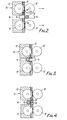
- Figure 2 is a cross-sectional view of the head 15 and the wire 10 with the wire 10 in the same position as shown in Figure 1, and Figure 2 shows the head 15 and the wire 10 after the head has moved to straddle the wire.
- the head 15 also includes two movable tape welding tools 18 and a tape cutting tool 20 (not shown in Figure 1).
- the wire is moved between the pulleys 14 until the appropriate position on the wire for an identifying sleeve is adjacent to the plastic strip 11.
- the head 15 moves across the wire to the position shown in Figure 3, and the plastics tape 11 is dragged partway around the wire to wrap it by about 180°.
- Complete encirclement of the wire by the tape 11 is completed by movement of the welding tools 18 towards each other until their ends abut with a double layer of tape between them ( Figure 4).
- the tape is then welded and simultaneously the cutting tool 20 moves down to cut the tape ( Figure 5).
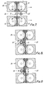
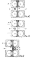
- Figures 7 to 12 illustrate the sequence of operation of another embodiment of the invention, again in cross-sectional view across part of a supporting head 25.
- the head is similar to the head 15 shown in Figures 1 to 6 but it is provided with two slots 26 and 27,two sets of spaced welding tools 28 and two cutting tools 30.
- the wire 10 is guided by the pulleys 14 as before, and the plastics tape 11 is moved by the rollers 12.
- the head 25 moves across the wire 10 so that the wire is moved from the slot 27 to the slot 26 ( Figure 7) and the plastics tape 11 is dragged around the wire to wrap it by about 180 0 .
- Encirclement of the wire by the tape is completed as the set of spaced welding tools 28 moves into abutment with the tape ( Figure 8).
- the tape is welded and cut by the cutting tool 30 between the spaced welds ( Figure 9).
- the welding and cutting tools now retract, the wire 10 is fed along by the pulleys 14 and the tape 11 increments down (Figure 11).
- the head 25 now returns to the position shown in Figure 7 in which the wire 10 is in the slot 27 and again the tape 11 is dragged around the wire and the other set of welding tools 28 moves into abutment with the tape to complete the encirclement of the wire 10 by the tape 11 ( Figure 12).
- the sequence thus repeats, with a sleeve being wrapped around the wire every time the head 25 moves across the wire.
- the operation of the stations would preferably be controlled by computer.
- the system may also be applied to many other articles which require some form of identification, such as hydraulic pipes and other elongate or rod-like articles.
Landscapes
- Engineering & Computer Science (AREA)
- Mechanical Engineering (AREA)
- Lining Or Joining Of Plastics Or The Like (AREA)
- Control And Other Processes For Unpacking Of Materials (AREA)
- Packages (AREA)
- Acyclic And Carbocyclic Compounds In Medicinal Compositions (AREA)
- Medicinal Preparation (AREA)
- Basic Packing Technique (AREA)
Priority Applications (1)
| Application Number | Priority Date | Filing Date | Title |
|---|---|---|---|
| AT85306576T ATE42718T1 (de) | 1984-09-14 | 1985-09-16 | Vorrichtung zum umhuellen von gegenstaenden. |
Applications Claiming Priority (2)
| Application Number | Priority Date | Filing Date | Title |
|---|---|---|---|
| GB848423336A GB8423336D0 (en) | 1984-09-14 | 1984-09-14 | Enwrapping articles |
| GB8423336 | 1984-09-14 |
Publications (2)
| Publication Number | Publication Date |
|---|---|
| EP0176302A1 true EP0176302A1 (de) | 1986-04-02 |
| EP0176302B1 EP0176302B1 (de) | 1989-05-03 |
Family
ID=10566750
Family Applications (1)
| Application Number | Title | Priority Date | Filing Date |
|---|---|---|---|
| EP85306576A Expired EP0176302B1 (de) | 1984-09-14 | 1985-09-16 | Vorrichtung zum Umhüllen von Gegenständen |
Country Status (4)
| Country | Link |
|---|---|
| EP (1) | EP0176302B1 (de) |
| AT (1) | ATE42718T1 (de) |
| DE (1) | DE3569915D1 (de) |
| GB (1) | GB8423336D0 (de) |
Cited By (3)
| Publication number | Priority date | Publication date | Assignee | Title |
|---|---|---|---|---|
| FR2621011A1 (fr) * | 1987-09-30 | 1989-03-31 | Aerospatiale | Machine pour la pose d'une etiquette sur une piece de revolution et cassette utilisable dans une telle machine |
| WO1997029431A1 (fr) * | 1996-02-09 | 1997-08-14 | A.R.I. Application Realisation Informatique (S.A.R.L) | Systeme de brassage informatique |
| EP1832519A1 (de) * | 2006-03-08 | 2007-09-12 | Manfred Mödder | Verfahren und Vorrichtung zum Markieren lang gestreckter Objekte |
Citations (1)
| Publication number | Priority date | Publication date | Assignee | Title |
|---|---|---|---|---|
| GB2092984A (en) * | 1981-02-13 | 1982-08-25 | Elsner Eng Works Inc | Apparatus for and method of wrapping rolls |
-
1984
- 1984-09-14 GB GB848423336A patent/GB8423336D0/en active Pending
-
1985
- 1985-09-16 DE DE8585306576T patent/DE3569915D1/de not_active Expired
- 1985-09-16 EP EP85306576A patent/EP0176302B1/de not_active Expired
- 1985-09-16 AT AT85306576T patent/ATE42718T1/de not_active IP Right Cessation
Patent Citations (1)
| Publication number | Priority date | Publication date | Assignee | Title |
|---|---|---|---|---|
| GB2092984A (en) * | 1981-02-13 | 1982-08-25 | Elsner Eng Works Inc | Apparatus for and method of wrapping rolls |
Cited By (4)
| Publication number | Priority date | Publication date | Assignee | Title |
|---|---|---|---|---|
| FR2621011A1 (fr) * | 1987-09-30 | 1989-03-31 | Aerospatiale | Machine pour la pose d'une etiquette sur une piece de revolution et cassette utilisable dans une telle machine |
| WO1997029431A1 (fr) * | 1996-02-09 | 1997-08-14 | A.R.I. Application Realisation Informatique (S.A.R.L) | Systeme de brassage informatique |
| FR2744868A1 (fr) * | 1996-02-09 | 1997-08-14 | A R I Applic Realisation Inf | Systeme de brassage informatique |
| EP1832519A1 (de) * | 2006-03-08 | 2007-09-12 | Manfred Mödder | Verfahren und Vorrichtung zum Markieren lang gestreckter Objekte |
Also Published As
| Publication number | Publication date |
|---|---|
| DE3569915D1 (en) | 1989-06-08 |
| ATE42718T1 (de) | 1989-05-15 |
| EP0176302B1 (de) | 1989-05-03 |
| GB8423336D0 (en) | 1984-10-17 |
Similar Documents
| Publication | Publication Date | Title |
|---|---|---|
| US4653160A (en) | Apparatus for making finished wire harnesses or sub-assemblies therefor | |
| US3363309A (en) | Method of attaching terminals to a length of insulated conductor | |
| CA1069684A (en) | Manufacture of wiring harness | |
| DE3873645D1 (de) | Verfahren und werkzeug zum automatischen binden von kabeln mit einem endlosen bindestreifen. | |
| US4631822A (en) | Process for producing cables fitted with electrical connectors | |
| US5781990A (en) | Method and device for preparing cable for separating into portions | |
| ES434786A1 (es) | Aparato para tratar conductores electricos. | |
| GB2024052A (en) | Method and apparatus for wiring loom production | |
| JPS6463285A (en) | Method and apparatus for crimping a plurality of conductive wire | |
| EP0143960A3 (en) | Device for straightening and cutting wire-or bar-shaped material into lengths | |
| US4347651A (en) | System for manufacturing connection wires | |
| EP0181780A2 (de) | Drahtvorbereitungssystem | |
| US5033188A (en) | Method of making an electrical harness | |
| US9573258B2 (en) | Pulling head work station | |
| EP0274240A3 (de) | Drahtbearbeitungsanlage | |
| EP0176302B1 (de) | Vorrichtung zum Umhüllen von Gegenständen | |
| DE4413577A1 (de) | Vorrichtung und Verfahren zum vollautomatischen Konfektionieren von flexiblen, endlosen Einzeladern | |
| ATE35955T1 (de) | Vorrichtung zum verpacken von guetern mittels einer schrumpffolie. | |
| JP2916048B2 (ja) | 電線の端末処理装置 | |
| HK23789A (en) | Method of and apparatus for bundling elongate articles | |
| US3594900A (en) | Method and apparatus for connecting pairs of conductors | |
| US5067399A (en) | Wire marking apparatus for marking selected codes onto any of a plurality of wires | |
| KR980700924A (ko) | 다발 물체 특히, 케이블 부품을 결합하기 위한 방법 및 장치와 결합재(process for binding bunched objects, especially cablese ctions, device therefor and a binding material) | |
| US5628108A (en) | Wire transfer and cutting assembly suitable for use with multiple wire termination apparatus | |
| EP0365137A1 (de) | Verfahren zur Herstellung eines Kabelstranges |
Legal Events
| Date | Code | Title | Description |
|---|---|---|---|
| PUAI | Public reference made under article 153(3) epc to a published international application that has entered the european phase |
Free format text: ORIGINAL CODE: 0009012 |
|
| AK | Designated contracting states |
Kind code of ref document: A1 Designated state(s): AT BE CH DE FR GB IT LI LU NL SE |
|
| 17P | Request for examination filed |
Effective date: 19860906 |
|
| 17Q | First examination report despatched |
Effective date: 19870601 |
|
| GRAA | (expected) grant |
Free format text: ORIGINAL CODE: 0009210 |
|
| AK | Designated contracting states |
Kind code of ref document: B1 Designated state(s): AT BE CH DE FR GB IT LI LU NL SE |
|
| REF | Corresponds to: |
Ref document number: 42718 Country of ref document: AT Date of ref document: 19890515 Kind code of ref document: T |
|
| ITF | It: translation for a ep patent filed | ||
| REF | Corresponds to: |
Ref document number: 3569915 Country of ref document: DE Date of ref document: 19890608 |
|
| ET | Fr: translation filed | ||
| PG25 | Lapsed in a contracting state [announced via postgrant information from national office to epo] |
Ref country code: LU Free format text: LAPSE BECAUSE OF NON-PAYMENT OF DUE FEES Effective date: 19890930 |
|
| PLBE | No opposition filed within time limit |
Free format text: ORIGINAL CODE: 0009261 |
|
| STAA | Information on the status of an ep patent application or granted ep patent |
Free format text: STATUS: NO OPPOSITION FILED WITHIN TIME LIMIT |
|
| 26N | No opposition filed | ||
| PGFP | Annual fee paid to national office [announced via postgrant information from national office to epo] |
Ref country code: GB Payment date: 19900803 Year of fee payment: 6 |
|
| PGFP | Annual fee paid to national office [announced via postgrant information from national office to epo] |
Ref country code: AT Payment date: 19900913 Year of fee payment: 6 |
|
| PGFP | Annual fee paid to national office [announced via postgrant information from national office to epo] |
Ref country code: FR Payment date: 19900919 Year of fee payment: 6 |
|
| PGFP | Annual fee paid to national office [announced via postgrant information from national office to epo] |
Ref country code: SE Payment date: 19900921 Year of fee payment: 6 |
|
| PGFP | Annual fee paid to national office [announced via postgrant information from national office to epo] |
Ref country code: CH Payment date: 19900925 Year of fee payment: 6 |
|
| ITTA | It: last paid annual fee | ||
| PGFP | Annual fee paid to national office [announced via postgrant information from national office to epo] |
Ref country code: NL Payment date: 19900930 Year of fee payment: 6 |
|
| PGFP | Annual fee paid to national office [announced via postgrant information from national office to epo] |
Ref country code: LU Payment date: 19901002 Year of fee payment: 6 |
|
| PGFP | Annual fee paid to national office [announced via postgrant information from national office to epo] |
Ref country code: DE Payment date: 19901031 Year of fee payment: 6 |
|
| PGFP | Annual fee paid to national office [announced via postgrant information from national office to epo] |
Ref country code: BE Payment date: 19901108 Year of fee payment: 6 |
|
| REG | Reference to a national code |
Ref country code: CH Ref legal event code: PUE Owner name: SIEMENS PLESSEY ELECTRONIC SYSTEMS LIMITED |
|
| REG | Reference to a national code |
Ref country code: FR Ref legal event code: TP |
|
| REG | Reference to a national code |
Ref country code: GB Ref legal event code: 732 |
|
| ITPR | It: changes in ownership of a european patent |
Owner name: CESSIONE;PLESSEY ELECTRONIC SYSTEMS LIMITED |
|
| PG25 | Lapsed in a contracting state [announced via postgrant information from national office to epo] |
Ref country code: GB Effective date: 19910916 Ref country code: AT Effective date: 19910916 |
|
| PG25 | Lapsed in a contracting state [announced via postgrant information from national office to epo] |
Ref country code: SE Effective date: 19910917 |
|
| PG25 | Lapsed in a contracting state [announced via postgrant information from national office to epo] |
Ref country code: LI Effective date: 19910930 Ref country code: CH Effective date: 19910930 Ref country code: BE Effective date: 19910930 |
|
| BERE | Be: lapsed |
Owner name: SIEMENS PLESSEY ELECTRONIC SYSTEMS LTD. Effective date: 19910930 |
|
| PG25 | Lapsed in a contracting state [announced via postgrant information from national office to epo] |
Ref country code: NL Effective date: 19920401 |
|
| GBPC | Gb: european patent ceased through non-payment of renewal fee | ||
| NLV4 | Nl: lapsed or anulled due to non-payment of the annual fee | ||
| PG25 | Lapsed in a contracting state [announced via postgrant information from national office to epo] |
Ref country code: FR Effective date: 19920529 |
|
| REG | Reference to a national code |
Ref country code: CH Ref legal event code: PL |
|
| PG25 | Lapsed in a contracting state [announced via postgrant information from national office to epo] |
Ref country code: DE Effective date: 19920602 |
|
| REG | Reference to a national code |
Ref country code: FR Ref legal event code: ST |
|
| EUG | Se: european patent has lapsed |
Ref document number: 85306576.1 Effective date: 19920408 |