EP0176313A2 - Appareil de mesure pour gaz brûlants - Google Patents
Appareil de mesure pour gaz brûlants Download PDFInfo
- Publication number
- EP0176313A2 EP0176313A2 EP85306623A EP85306623A EP0176313A2 EP 0176313 A2 EP0176313 A2 EP 0176313A2 EP 85306623 A EP85306623 A EP 85306623A EP 85306623 A EP85306623 A EP 85306623A EP 0176313 A2 EP0176313 A2 EP 0176313A2
- Authority
- EP
- European Patent Office
- Prior art keywords
- electrode
- electrolyte
- sheath
- gas
- improvement
- Prior art date
- Legal status (The legal status is an assumption and is not a legal conclusion. Google has not performed a legal analysis and makes no representation as to the accuracy of the status listed.)
- Granted
Links
- 239000000523 sample Substances 0.000 title abstract description 42
- 239000007789 gas Substances 0.000 claims abstract description 90
- PXHVJJICTQNCMI-UHFFFAOYSA-N Nickel Chemical compound [Ni] PXHVJJICTQNCMI-UHFFFAOYSA-N 0.000 claims abstract description 64
- 239000003792 electrolyte Substances 0.000 claims abstract description 61
- 229910052759 nickel Inorganic materials 0.000 claims abstract description 32
- QVGXLLKOCUKJST-UHFFFAOYSA-N atomic oxygen Chemical compound [O] QVGXLLKOCUKJST-UHFFFAOYSA-N 0.000 claims abstract description 26
- 239000001301 oxygen Substances 0.000 claims abstract description 26
- 229910052760 oxygen Inorganic materials 0.000 claims abstract description 26
- 229910045601 alloy Inorganic materials 0.000 claims abstract description 22
- 239000000956 alloy Substances 0.000 claims abstract description 22
- 238000006555 catalytic reaction Methods 0.000 claims abstract description 14
- 239000004020 conductor Substances 0.000 claims abstract description 5
- XEEYBQQBJWHFJM-UHFFFAOYSA-N Iron Chemical compound [Fe] XEEYBQQBJWHFJM-UHFFFAOYSA-N 0.000 claims description 16
- WABPQHHGFIMREM-UHFFFAOYSA-N lead(0) Chemical compound [Pb] WABPQHHGFIMREM-UHFFFAOYSA-N 0.000 claims description 15
- VYZAMTAEIAYCRO-UHFFFAOYSA-N Chromium Chemical compound [Cr] VYZAMTAEIAYCRO-UHFFFAOYSA-N 0.000 claims description 13
- 229910052804 chromium Inorganic materials 0.000 claims description 13
- 239000011651 chromium Substances 0.000 claims description 13
- 238000006243 chemical reaction Methods 0.000 claims description 10
- 229910052742 iron Inorganic materials 0.000 claims description 8
- 238000005259 measurement Methods 0.000 claims description 8
- 229910000510 noble metal Inorganic materials 0.000 claims description 8
- 229910052710 silicon Inorganic materials 0.000 claims description 8
- 239000010703 silicon Substances 0.000 claims description 8
- 239000007784 solid electrolyte Substances 0.000 claims description 6
- ZOKXTWBITQBERF-UHFFFAOYSA-N Molybdenum Chemical compound [Mo] ZOKXTWBITQBERF-UHFFFAOYSA-N 0.000 claims description 3
- 230000003197 catalytic effect Effects 0.000 claims description 3
- 229910017052 cobalt Inorganic materials 0.000 claims description 3
- 239000010941 cobalt Substances 0.000 claims description 3
- GUTLYIVDDKVIGB-UHFFFAOYSA-N cobalt atom Chemical compound [Co] GUTLYIVDDKVIGB-UHFFFAOYSA-N 0.000 claims description 3
- 229910052750 molybdenum Inorganic materials 0.000 claims description 3
- 239000011733 molybdenum Substances 0.000 claims description 3
- WFKWXMTUELFFGS-UHFFFAOYSA-N tungsten Chemical compound [W] WFKWXMTUELFFGS-UHFFFAOYSA-N 0.000 claims description 3
- 229910052721 tungsten Inorganic materials 0.000 claims description 3
- 239000010937 tungsten Substances 0.000 claims description 3
- 229910010293 ceramic material Inorganic materials 0.000 claims description 2
- -1 electrode Substances 0.000 claims description 2
- WPBNNNQJVZRUHP-UHFFFAOYSA-L manganese(2+);methyl n-[[2-(methoxycarbonylcarbamothioylamino)phenyl]carbamothioyl]carbamate;n-[2-(sulfidocarbothioylamino)ethyl]carbamodithioate Chemical compound [Mn+2].[S-]C(=S)NCCNC([S-])=S.COC(=O)NC(=S)NC1=CC=CC=C1NC(=S)NC(=O)OC WPBNNNQJVZRUHP-UHFFFAOYSA-L 0.000 claims 2
- 239000007787 solid Substances 0.000 claims 2
- 238000009423 ventilation Methods 0.000 abstract description 9
- 230000005923 long-lasting effect Effects 0.000 abstract description 3
- BASFCYQUMIYNBI-UHFFFAOYSA-N platinum Chemical compound [Pt] BASFCYQUMIYNBI-UHFFFAOYSA-N 0.000 description 12
- 239000000919 ceramic Substances 0.000 description 10
- 229910052751 metal Inorganic materials 0.000 description 10
- 239000002184 metal Substances 0.000 description 10
- OKTJSMMVPCPJKN-UHFFFAOYSA-N Carbon Chemical compound [C] OKTJSMMVPCPJKN-UHFFFAOYSA-N 0.000 description 8
- 229910052799 carbon Inorganic materials 0.000 description 8
- 230000000694 effects Effects 0.000 description 7
- 239000000463 material Substances 0.000 description 7
- 239000000203 mixture Substances 0.000 description 7
- 229910000990 Ni alloy Inorganic materials 0.000 description 6
- 229910052697 platinum Inorganic materials 0.000 description 6
- 230000002441 reversible effect Effects 0.000 description 6
- 239000000126 substance Substances 0.000 description 6
- 238000005255 carburizing Methods 0.000 description 5
- 150000002739 metals Chemical class 0.000 description 5
- VNWKTOKETHGBQD-UHFFFAOYSA-N methane Chemical compound C VNWKTOKETHGBQD-UHFFFAOYSA-N 0.000 description 5
- 229910052782 aluminium Inorganic materials 0.000 description 3
- XAGFODPZIPBFFR-UHFFFAOYSA-N aluminium Chemical compound [Al] XAGFODPZIPBFFR-UHFFFAOYSA-N 0.000 description 3
- 230000015572 biosynthetic process Effects 0.000 description 3
- 229910002092 carbon dioxide Inorganic materials 0.000 description 3
- 238000010276 construction Methods 0.000 description 3
- 238000012986 modification Methods 0.000 description 3
- 230000004048 modification Effects 0.000 description 3
- CURLTUGMZLYLDI-UHFFFAOYSA-N Carbon dioxide Chemical compound O=C=O CURLTUGMZLYLDI-UHFFFAOYSA-N 0.000 description 2
- ATUOYWHBWRKTHZ-UHFFFAOYSA-N Propane Chemical compound CCC ATUOYWHBWRKTHZ-UHFFFAOYSA-N 0.000 description 2
- VYPSYNLAJGMNEJ-UHFFFAOYSA-N Silicium dioxide Chemical compound O=[Si]=O VYPSYNLAJGMNEJ-UHFFFAOYSA-N 0.000 description 2
- 229910000831 Steel Inorganic materials 0.000 description 2
- NINIDFKCEFEMDL-UHFFFAOYSA-N Sulfur Chemical compound [S] NINIDFKCEFEMDL-UHFFFAOYSA-N 0.000 description 2
- 239000005864 Sulphur Substances 0.000 description 2
- MCMNRKCIXSYSNV-UHFFFAOYSA-N Zirconium dioxide Chemical compound O=[Zr]=O MCMNRKCIXSYSNV-UHFFFAOYSA-N 0.000 description 2
- 239000011248 coating agent Substances 0.000 description 2
- 238000000576 coating method Methods 0.000 description 2
- 230000001419 dependent effect Effects 0.000 description 2
- 238000013461 design Methods 0.000 description 2
- 239000007772 electrode material Substances 0.000 description 2
- 230000003647 oxidation Effects 0.000 description 2
- 238000007254 oxidation reaction Methods 0.000 description 2
- 230000001590 oxidative effect Effects 0.000 description 2
- 238000012856 packing Methods 0.000 description 2
- 229910002077 partially stabilized zirconia Inorganic materials 0.000 description 2
- 230000001681 protective effect Effects 0.000 description 2
- 229910052703 rhodium Inorganic materials 0.000 description 2
- 239000010948 rhodium Substances 0.000 description 2
- MHOVAHRLVXNVSD-UHFFFAOYSA-N rhodium atom Chemical compound [Rh] MHOVAHRLVXNVSD-UHFFFAOYSA-N 0.000 description 2
- 229910002076 stabilized zirconia Inorganic materials 0.000 description 2
- 239000010959 steel Substances 0.000 description 2
- 238000012360 testing method Methods 0.000 description 2
- UGFAIRIUMAVXCW-UHFFFAOYSA-N Carbon monoxide Chemical compound [O+]#[C-] UGFAIRIUMAVXCW-UHFFFAOYSA-N 0.000 description 1
- RYGMFSIKBFXOCR-UHFFFAOYSA-N Copper Chemical compound [Cu] RYGMFSIKBFXOCR-UHFFFAOYSA-N 0.000 description 1
- PWHULOQIROXLJO-UHFFFAOYSA-N Manganese Chemical compound [Mn] PWHULOQIROXLJO-UHFFFAOYSA-N 0.000 description 1
- 229910018487 Ni—Cr Inorganic materials 0.000 description 1
- 229910001260 Pt alloy Inorganic materials 0.000 description 1
- HCHKCACWOHOZIP-UHFFFAOYSA-N Zinc Chemical compound [Zn] HCHKCACWOHOZIP-UHFFFAOYSA-N 0.000 description 1
- 230000001464 adherent effect Effects 0.000 description 1
- 238000005275 alloying Methods 0.000 description 1
- 239000001273 butane Substances 0.000 description 1
- 239000001569 carbon dioxide Substances 0.000 description 1
- 238000005256 carbonitriding Methods 0.000 description 1
- 239000003054 catalyst Substances 0.000 description 1
- 230000008859 change Effects 0.000 description 1
- BIJOYKCOMBZXAE-UHFFFAOYSA-N chromium iron nickel Chemical compound [Cr].[Fe].[Ni] BIJOYKCOMBZXAE-UHFFFAOYSA-N 0.000 description 1
- VNNRSPGTAMTISX-UHFFFAOYSA-N chromium nickel Chemical compound [Cr].[Ni] VNNRSPGTAMTISX-UHFFFAOYSA-N 0.000 description 1
- 239000000356 contaminant Substances 0.000 description 1
- 239000010949 copper Substances 0.000 description 1
- 229910052802 copper Inorganic materials 0.000 description 1
- 230000001627 detrimental effect Effects 0.000 description 1
- 238000011161 development Methods 0.000 description 1
- 230000005496 eutectics Effects 0.000 description 1
- 239000003546 flue gas Substances 0.000 description 1
- 239000000446 fuel Substances 0.000 description 1
- 239000012535 impurity Substances 0.000 description 1
- 229910052748 manganese Inorganic materials 0.000 description 1
- 239000011572 manganese Substances 0.000 description 1
- 238000004519 manufacturing process Methods 0.000 description 1
- 230000008018 melting Effects 0.000 description 1
- 238000002844 melting Methods 0.000 description 1
- 229910001092 metal group alloy Inorganic materials 0.000 description 1
- 238000000034 method Methods 0.000 description 1
- IJDNQMDRQITEOD-UHFFFAOYSA-N n-butane Chemical compound CCCC IJDNQMDRQITEOD-UHFFFAOYSA-N 0.000 description 1
- OFBQJSOFQDEBGM-UHFFFAOYSA-N n-pentane Natural products CCCCC OFBQJSOFQDEBGM-UHFFFAOYSA-N 0.000 description 1
- 229910000480 nickel oxide Inorganic materials 0.000 description 1
- 229910000623 nickel–chromium alloy Inorganic materials 0.000 description 1
- GNRSAWUEBMWBQH-UHFFFAOYSA-N oxonickel Chemical compound [Ni]=O GNRSAWUEBMWBQH-UHFFFAOYSA-N 0.000 description 1
- 230000035515 penetration Effects 0.000 description 1
- 230000008569 process Effects 0.000 description 1
- 239000001294 propane Substances 0.000 description 1
- 230000009467 reduction Effects 0.000 description 1
- 230000035939 shock Effects 0.000 description 1
- 239000000377 silicon dioxide Substances 0.000 description 1
- WWNBZGLDODTKEM-UHFFFAOYSA-N sulfanylidenenickel Chemical compound [Ni]=S WWNBZGLDODTKEM-UHFFFAOYSA-N 0.000 description 1
- XLYOFNOQVPJJNP-UHFFFAOYSA-N water Substances O XLYOFNOQVPJJNP-UHFFFAOYSA-N 0.000 description 1
- 229910001233 yttria-stabilized zirconia Inorganic materials 0.000 description 1
- 229910052725 zinc Inorganic materials 0.000 description 1
- 239000011701 zinc Substances 0.000 description 1
Images

Classifications
-
- G—PHYSICS
- G01—MEASURING; TESTING
- G01N—INVESTIGATING OR ANALYSING MATERIALS BY DETERMINING THEIR CHEMICAL OR PHYSICAL PROPERTIES
- G01N27/00—Investigating or analysing materials by the use of electric, electrochemical, or magnetic means
- G01N27/26—Investigating or analysing materials by the use of electric, electrochemical, or magnetic means by investigating electrochemical variables; by using electrolysis or electrophoresis
- G01N27/403—Cells and electrode assemblies
- G01N27/406—Cells and probes with solid electrolytes
- G01N27/407—Cells and probes with solid electrolytes for investigating or analysing gases
- G01N27/4077—Means for protecting the electrolyte or the electrodes
Definitions
- This invention pertains to measuring apparatus, and more particularly to apparatus for measuring gas characteristics.
- the major components of all oxygen sensors are the electrolyte, the electrodes, i.e., anode, cathode, and the electrical lead wires which make electrical contact with the electrodes.
- the selection of a proper electrode material generally requires the satisfaction of chemical, electro-chemical, mechanical, and economical criteria. Platinum and other noble metals often meet the performance criteria, but they are very expensive.
- the specific electrode material and design are usually dependent on the particular environment to which it is subjected.
- oxygen sensors have been used in a wide variety of applications, such as motor vehicle exhaust, flue gas, molten copper or steel, and metal heat treating. As an example of the latter application, oxygen sensors are used for controlling the carbon potential in carburizing atmospheres. Control of Surface Carbon Content, Metals Handbook, Vol. 4, p. 417-431, 9th Edition, 1981. In addition to the aforementioned patents, oxygen sensors are disclosed in U.S. Patent 4,193,857, German Patent 2,401,134, and Australian Provisional Specification 47,828/79.
- the electrode in the furnace atmosphere should maintain thermodynamic equilibrium between the oxygen activity within the atmosphere as a whole and the oxygen activity at the surface of the electrolyte. This condition is not always met in prior oxygen sensors.
- nickel for example, has been used for anodes in fuel cells.
- nickel possesses high temperature properties desirable in gas probes, it has been discovered that in heat treat atmospheres where the gases are not in equilibrium nickel acts as a catalyst which alters the gas composition locally which results in a non-representative voltage output. Specifically, in heat treating atmospheres it has been found by our tests that the presence of nickel increases the rate of reaction of methane with water or carbon dioxide adjacent the anode surface. The altered gas composition generates a larger and non-representative voltage.
- the reason the nickel electrode sensor gave a higher emf reading was the catalytic reaction of the nickel electrode on the following reactions for example: (i.e., the rate of the reaction of CH 4 with H20 or C0 2 was increased and thus reduced the amount of H 2 0 and C0 2 in the gas phase that was adjacent to the surface of the nickel electrode). This effect produced a lower oxygen potential at the electrode and therefore produced a larger emf.
- a long lasting hot gas measuring probe which accurately and consistently measures the properties of gases without requiring the use of noble metals as the outer electrode or anode. This is accomplished by apparatus which includes electrodes composed of nickel, chromium and other selected elements to enhance carburization and oxidation resistance and minimize the undesirable catalytic reaction heretofore mentioned.
- electrodes made of nickel alloys containing about 35-60% nickel and certain other elements significantly improve the probe to provide long service life while having acceptably low catalytic effects in the zones of contact with the electrolyte.
- the nickel containing alloy electrodes enable accurate and repeatable measurements to be made by the probe, and the electrodes are considerably less expensive than the platinum or other noble metal electrodes formerly used.
- a preferred electrode range is an alloy containing about 35-45% nickel, 19-25% chromium, 43-18% iron, and .5-1.25% silicon.
- the relatively small amounts of silicon and/or aluminum together with the chromium ranges disclosed herein form a stable oxide layer on.the anode. The oxide layer minimizes penetration of carbon in the carburizing atmosphere into the parent metal.
- Carburization of the anode removes carbon from the gas adjacent anode which alters the gas locally and results in a lower and non-representative probe voltage. Also, if the carbon potential in the furnace atmosphere is lowered, then the reverse process can occur and the anode will give up carbon to enrich the local gas atmosphere resulting in a higher probe voltage.
- thermodynamic equilibrium of the oxygen activity at the three phase contact zone of gas, electrode, and electrolyte is a necessary condition for obtaining a reversible oxygen electrode. Measurement accuracy and repeatability require that both the electrodes be reversible with respect to oxygen.
- the gas at the contact zone should be representative of the gas in the furnace for accurate readings. It has been discovered that good circulation and gas exchange of the gas adjacent to the anode with furnace gas is necessary for measurement accuracy and repeatability. Any reaction such as oxidation, reduction or carburization between the electrode and gas in addition to the aforementioned catalytic reaction could effect the local gas composition and give erroneous results.
- one embodiment of the present invention is designed with a configuration with a line contact between the electrolyte and electrode with suitable openings and grooves through which the gas to be measured continuously flows past the three phase contact zones.
- a point contact would be the optimum contact for exchange with the gas phase as disclosed in a paper printed in The Journal of Electro-Chemical Society, February, 1976, page 204-212.
- the contact resistance in such a commercial device would be too high for practical use and it would be difficult to mechanically maintain the geometry.
- line .contact between the electrolyte and electrode as disclosed hereinafter provides some of the advantages of a point contact in affording good ventilation and gas movement.
- the probe comprises a hollow cylindrical sheath closed at one end with a flat plate which serves as the anode.
- the sheath can be composed of the same material as the electrode plate, thereby eliminating the need for an electrical lead wire from the electrode to the probe electronic circuitry.
- the electrode plate contains a centrally located opening therethrough adapted to contact and support the ball nosed or hemispherical end of a tubular electrolyte.
- the electrolyte may be composed of stabilized or partially stabilized zirconia, as is known in the art.
- the inside face of the electrode plate is constructed with several radial grooves, and the sheath wall contains numerous perforations.
- Hot gas is exchanged through the openings in the electrode plate, through the radial grooves, past the ball nosed end of the electrolyte, and through the sheath perforations.
- a cathode is inside the tubular electrolyte so as to contact the interior wall thereof opposite the external ball nose. Electrical lead wires connect the cathode with the remainder of the measuring circuitry in a known fashion.
- the flat end plate has a modified groove pattern. The sheath perforations are placed as close as possible to the junction of the sheath wall and the end electrode plate. Adequate ventilation is provided to the zones of contact through the central opening and grooves and the nearby sheath perforations.
- the anode is disc-shaped with projecting converging walls which guide the flat end of tubular electrolyte to positively position the electrolyte over a central aperture in a flat portion.
- the end of the electrode is fabricated with a central hole passing therethrough and several radial grooves in the inside face of the end wall. Additional holes may also be formed through the grooves. Gas passing through the holes and grooves flows between the corresponding portions of the electrolyte and electrode walls.
- This anode may be used in conjunction with a sheath of the same material or with a ceramic sheath.
- a perforated and closed ended ceramic sheath is utilized to hold a disc-shaped electrode adjacent the inside surface of the sheath closed end.
- the disc-shaped electrode and sheath end wall have communicating central holes therethrough.
- a stabilized or partially stabilized zirconia electrolyte having a ball nose at one end thereof is supported on the anode which also has radial grooves in the inside face thereof.
- a lead wire which may be of the same material as the anode is bonded thereto for conducting the generated voltage to the remainder of the control circuitry.
- the lead wire may be a large diameter wire or rod.
- a further modified embodiment provides a probe with a gas pump for use with a furnace which has poor circulation. In that situation, the ceramic or metal sheath is not perforated. Rather, the gas is drawn through the central opening in the end of the probe, through the radial grooves and past the electrolyte along the interior of the sheath, through a flow meter, a pump, and exhausted or returned back into the furnace in a closed loop.
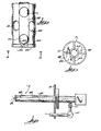
- FIGs. 1 and 2 the gas contacting end 1 of.a hot gas measuring probe 3 is illustrated.
- the general construction of the measuring probe 3 is disclosed in U.S. Patents 4,101,404 and 4,186,072, both of which patents are hereby incorporated by reference into the present specification.
- the hot gas measuring probe is mounted to the side wall of a furnace, not shown in Figs. 1 and 2, with the gas contacting end inserted into the furnace for measuring the properties of the gas therein.
- the hot gas measuring probe of the present invention includes a support tube or sheath 24 which can be fastened by a bracket to the furnace wall.
- an end plate 82 which serves as the anode.
- the sheath and end plate 82 serve as a combined electrical conductor and electrode forming a portion of the apparatus for obtaining voltage measurements based on the thermodynamic properties of the furnace gas.
- the gas probe further includes a solid electrolyte tube 28 which can be composed of yttria stabilized zirconia. The electrolyte tube 28 contacts the end plate 82, as will be fully explained hereinafter.
- the other electrode or cathode 38 is inserted into the electrolyte tube 28 and can be held in place therein by a spring loaded ceramic rod 40, as is described in the aforementioned patents 4,101,404 and 4,186,072.
- the ceramic rod 40 includes . one or more longitudinal bores 42, 99 for feeding a reference gas to the inside of the electrolyte tube and for receiving electrical lead wire 29 which conduct the voltage from the second electrode to the remainder of the instrument circuitry.
- the sheath 24 and end plate or anode 82 are manufactured from a material which satisfies the mechanical, chemical, electro-chemical, and economical criteria for gas probe electrodes as described in the paper by Tedman, et al in Journal of Electro Chemical Society, Vol. 9, page 1170-1175, September, 1969.
- alloys are selected for the probe disclosed herein to minimize the catalytic reaction described above.
- the nickel-chromium or iron nickel chromium alloy is relatively inexpensive and long lasting. The nickel content is sufficiently high so as to provide good mechanical properties at the high temperatures of heat treating furnaces.
- the nickel content is low enough so that the undesirable catalytic reactions at the three phase contact points caused by nickel is not detrimental to measurement accuracy and repeatability.
- Acceptable results are obtained when the material is a nickel alloy containing about 35-60% nickel, but the preferred range is from about 35-45% nickel.
- the criteria for an acceptable electrode or anode in accordance with the invention herein requires that the nickel alloy contain other important elements. Chromium, for example, is necessary for good mechanical properties at high temperatures. The chromium also promotes the formation of an adherent and protective oxide film. A particularly important element is silicon, because even a relatively small amount of silicon together with chromium aids in forming a more protective oxide coating on the anode with good carburization resistance. Aluminum provides equivalent results. The oxide coating is very important for protecting the . electrode because it provides both oxidizing and carburizing resistance for the parent metal. Satisfactory results are obtained with an alloy composed of about 35-60% nickel, 19-25% chromium, 43-14% iron, and .2-1.5% silicon or aluminum.
- the preferred composition is 45% nickel, 25% chromium, 18% iron, 3% cobalt, 3% molybdenum, 3% tungsten, 1.5% manganese and 1.25% silicon.
- the preferred alloy for the anode 82 is available commercially under the trademarks RA333 and for the sheath 24 RA330. These trademarks are marks of Rolled Alloys of Temperance MI.
- the RA333 is more carburization resistant as well as meeting the other criteria. RA333 could also be used for the sheath but it is more expensive than RA330.
- the hot gas probe 3 illustrated in Fig. 1 is designed so that the three phase contact points between the electrolyte, electrode, and the gas are adequately ventilated with fresh gas, thereby assuring that the gas measured is representative of the furnace gas.
- thermodynamic equilibrium with respect to oxygen is vital if the probe is to give accurate and consistent results.
- the electrode end plate 82 is fabricated with a central opening 5.
- the solid electrolyte 28 has a ball nosed outer surface 7 which fits within and is centrally supported by the electrode plate along the periphery of the opening 5.
- a series of grooves 9 extend radially from the central opening in the inside face of the electrode plate. Consequently, the contacts between the electrolyte and electrode plate are along arcuate lines .11 created at the junction of the inside face of the electrode plate and the circumferential surface of the central opening. Gas whose properties are to be measured by the probe of the present invention is exchanged with the furnace and can pass through the central opening, adjacent the contact lines between the electrode plate and electrolyte, through the grooves, and into the interior 13 of the sheath 24, as illustrated by arrows 15.
- the sheath wall contains numerous perforations 17 through which the gas in the interior can flow back to the furnace, as illustrated by arrows 19.
- the gas can flow in the reverse direction or from either direction. It has been found that about 25-50% of the wall area of the sheath in the measuring region of the probe end should consist of perforations 17 where there is forced convection in the furnace because of a circulating fan.
- the zones of three phase contact between electrode, electrolyte, and gas, which occur along lines 11, are constantly supplied with fresh gas.
- the effect on probe accuracy and repeatability from undesirable catalytic reactions at the contact points which may be caused or enhanced by the nickel containing alloy electrode is minimized by the ventilation capability of the foregoing electrode or sheath configuration.
- Prior measuring probes such as those disclosed by U.S. Patent 4,193,857 and German Patent 2,401,134, include openings in the sheath in the region of the electrolyte-electrode interface.
- the prior devices failed to recognize the importance of rapid gas exchange to avoid local changes in composition caused by undesirable reactions described above.
- electrode 82' is formed as a closed end tube having an internal frusto-conical surface 21 which converges toward the end wall 23.
- the frusto-conical surface 21 terminates at a grooved flat surface 25 of end wall 23.
- the wall 23 has a central opening 27 therethrough and a series of grooves 39 which extend radially from the opening 27 in the inside face of the wall.
- the wall may also define small holes 41 extending therethrough,and opening in the grooves.
- the electrolyte 28' is formed as a tube having a flat end 33 which contacts the inside face of the electrode wall.
- the outer diameter of the electrolyte tube 28' is slightly less than the diameter of the grooved flat surface 25 so as to be centrally guided by the tapered surface 21.
- the electrode 82' is manufactured from the nickel containing alloy previously described.
- the sheath 24' may be of the same nickel containing alloy, in which case the electrode 82' is preferrably welded to the sheath.
- the sheath may also be of a ceramic material as illustrated in Figures 4 and 4a upon which the electrodes 82 and 82' are supported. If the sheath is made of ceramic, a lead wire 44 must be attached to the electrode for conducting the generated voltage to the remainder of the probe circuitry. Regardless of material, the wall 35 of sheath 24' has wall means defining preforations 17 which cover about 25-50% of the total wall area in the zone adjacent to the electrode or the region within about four inches of the electrode because the nickel containing alloy can cause the undesirable catalytic reaction. With the ceramic sheath the catalytic reaction is confined to the electrode area so the ventilation requirements are less.
- gas can flow or is exchanged, for example, through or from opening 27 and holes 41, along the grooves 39 and electrolyte end 33, through the annular space between the cylindrical surface 25 and outer surface of electrolyte tube 28', and out the sheath perforations, as indicated by arrows 37 which indicate gas exchange with the furnace atmosphere or in the reverse flow path.
- Figs. 4, 4a and 5 illustrate a further modified embodiment of-the present invention.
- the ceramic sheath disclosed in Figs. 4, 4a, and 5 may be advantageous in high temperature applications.
- the ceramic sheath is more subject to damage from thermal shock or mechanical stress.
- the metal alloy sheath is more durable and may be cheaper to manufacture.
- the electrode or anode 82 is manufactured from the nickel alloy previously described in the shape of a disc.
- a lead wire 44 can be of the same nickel alloy as the electrode and is bonded to the electrode 82 for conducting the generated voltage to the remainder of the instrument circuit.
- the electrode 82 rests in contact with the end wall 34 of ceramic sheath 24.
- the wall 34 and electrode disc 82 contain central apertures 45 and 47, respectively, and the ball nosed end of electrolyte 28 is centrally guided in the aperture 47.
- the face of the electrode opposite the sheath wall 34 contains a series of radial grooves 49 extending from the disc aperture 47..
- Fig. 4a is a modified embodiment in which the flat end of the electrolyte tube 28' is guided into position against the flat area 25 by the taper in the anode converging walls 21.
- FIGS 6 and 7 depict another modified embodiment of the present invention which is especially useful in miniature probes.
- the electrode 82 and sheath 24 are made of the nickel ⁇ containing alloy described previously, and they are welded or otherwise permanently joined.
- the electrode 82 has a central opening 53 into which the zirconia electrolyte 28 is placed.
- the inside face of the electrode 82 is radially grooved, as at 55.
- the sheath perforations 17 are located in the sheath wall as close as possible to the electrode. Gas flows through the opening 53, grooves 55, and perforations 17 in a manner substantially similar to that previously explained.
- FIG. 8 schematically illustrates a gas probe 3 mounted to a port 14 in a furnace wall. Any of the previously described electrode, sheath, and electrolyte combinations may be utilized with a pump. However, in all cases, the walls of the sheath 24 are not perforated. Gas is drawn through the respective openings in the electrode and past the three phase contact point between the electrode and electrolyte 28 and along the interior of the sheath to the pump 57, as illustrated by arrows 59. From the pump, the gas can be either discharged for remote disposal or may be returned to the furnace. A flow meter 61 with a valve is desirable to control flow rate.
- a pump can be employed with probe constructions as described in U.S. patents 4,101,404 and 4,186,072 with an axial opening rather than in the side walls.
- the lead wire 29 should be selected so that it will compensate for any thermal emf.
- the nickel containing alloy ranges disclosed 30-40% rhodium and the balance platinum alloy wire has provided satisfactory results when used for the inner electrode lead wire 29.
- the preferred lead wire for use with the preferred alloy is 70% platinum and 30% rhodium.
Landscapes
- Chemical & Material Sciences (AREA)
- Life Sciences & Earth Sciences (AREA)
- Health & Medical Sciences (AREA)
- Physics & Mathematics (AREA)
- Chemical Kinetics & Catalysis (AREA)
- Electrochemistry (AREA)
- Molecular Biology (AREA)
- Analytical Chemistry (AREA)
- Biochemistry (AREA)
- General Health & Medical Sciences (AREA)
- General Physics & Mathematics (AREA)
- Immunology (AREA)
- Pathology (AREA)
- Measuring Oxygen Concentration In Cells (AREA)
Applications Claiming Priority (2)
| Application Number | Priority Date | Filing Date | Title |
|---|---|---|---|
| US06/651,227 US4588493A (en) | 1984-09-17 | 1984-09-17 | Hot gas measuring probe |
| US651227 | 1984-09-17 |
Publications (3)
| Publication Number | Publication Date |
|---|---|
| EP0176313A2 true EP0176313A2 (fr) | 1986-04-02 |
| EP0176313A3 EP0176313A3 (en) | 1988-06-08 |
| EP0176313B1 EP0176313B1 (fr) | 1995-11-02 |
Family
ID=24612058
Family Applications (1)
| Application Number | Title | Priority Date | Filing Date |
|---|---|---|---|
| EP85306623A Expired - Lifetime EP0176313B1 (fr) | 1984-09-17 | 1985-09-17 | Appareil de mesure pour gaz brûlants |
Country Status (4)
| Country | Link |
|---|---|
| US (1) | US4588493A (fr) |
| EP (1) | EP0176313B1 (fr) |
| JP (2) | JPH0614021B2 (fr) |
| DE (1) | DE3588062T2 (fr) |
Cited By (6)
| Publication number | Priority date | Publication date | Assignee | Title |
|---|---|---|---|---|
| WO1988008131A1 (fr) * | 1987-04-13 | 1988-10-20 | Allied Corporation | Procede d'assemblage d'un ensemble detecteur d'o2 |
| WO2016100266A1 (fr) * | 2014-12-16 | 2016-06-23 | Eastman Chemical Company | Composants de biocapteurs déposés physiquement en phase vapeur |
| US11624723B2 (en) | 2016-09-16 | 2023-04-11 | Eastman Chemical Company | Biosensor electrodes prepared by physical vapor deposition |
| US11630075B2 (en) | 2016-09-16 | 2023-04-18 | Eastman Chemical Company | Biosensor electrodes prepared by physical vapor deposition |
| US11835481B2 (en) | 2016-06-15 | 2023-12-05 | Eastman Chemical Company | Physical vapor deposited biosensor components |
| US11881549B2 (en) | 2017-06-22 | 2024-01-23 | Eastman Chemical Company | Physical vapor deposited electrode for electrochemical sensors |
Families Citing this family (23)
| Publication number | Priority date | Publication date | Assignee | Title |
|---|---|---|---|---|
| US4814061A (en) * | 1987-12-03 | 1989-03-21 | Blumenthal Robert N | Hot gas measuring probe |
| US4944861A (en) * | 1989-04-03 | 1990-07-31 | Barber-Colman Company | Oxygen sensing probe having improved sensor tip and tip-supporting tube |
| US5324415A (en) * | 1989-06-09 | 1994-06-28 | Blumenthal Robert N | Apparatus and systems for analyzing a sample of treatment atmosphere having a carbon potential |
| US4966348A (en) * | 1989-06-30 | 1990-10-30 | Lindberg Corp. | Method and apparatus for monitoring atmosphere in furnaces |
| JPH03162664A (ja) * | 1989-11-21 | 1991-07-12 | Chugai Ro Co Ltd | 酸素分圧計 |
| US5211820A (en) * | 1991-04-04 | 1993-05-18 | Surface Combustion, Inc. | Gas analysis system for furnaces and the like |
| US5137616A (en) * | 1991-04-04 | 1992-08-11 | Surface Combustion, Inc. | Gas analysis system for furnaces and the like |
| ES2118187T3 (es) * | 1992-06-30 | 1998-09-16 | Int Control Automation Finance | Analizadores del contenido de oxigeno. |
| US5635044A (en) * | 1995-08-11 | 1997-06-03 | Lotze; Thomas H. | Electrode for zirconia oxygen sensors |
| US5851369A (en) * | 1996-09-20 | 1998-12-22 | Marathon Monitors, Inc. | Electrolytic sensor providing controlled burn-off of deposits on the electrodes |
| US6612154B1 (en) * | 1998-12-22 | 2003-09-02 | Furnace Control Corp. | Systems and methods for monitoring or controlling the ratio of hydrogen to water vapor in metal heat treating atmospheres |
| US6591215B1 (en) * | 1999-02-18 | 2003-07-08 | Furnace Control Corp. | Systems and methods for controlling the activity of carbon in heat treating atmospheres |
| DE19942740A1 (de) * | 1999-09-07 | 2001-03-22 | Heraeus Electro Nite Int | Gehäuse für einen Sensor |
| US6691553B2 (en) * | 2000-08-29 | 2004-02-17 | Delphi Technologies, Inc. | Gas sensor protective shield |
| US6752002B2 (en) * | 2001-06-11 | 2004-06-22 | Marathon Sensors, Inc. | Sensor |
| US20030084728A1 (en) * | 2001-11-06 | 2003-05-08 | Boltz Eric S. | Modular electrolytic sensor |
| DE10237171A1 (de) * | 2002-08-14 | 2004-03-04 | Robert Bosch Gmbh | Gasmessfühler |
| US7466799B2 (en) * | 2003-04-09 | 2008-12-16 | Varian Medical Systems, Inc. | X-ray tube having an internal radiation shield |
| US20060059987A1 (en) * | 2004-09-21 | 2006-03-23 | Waukee Engineering Company, Inc. | Systems and methods for sensing and/or measuring flow rate of gases based upon mass flow conditions |
| US20080187850A1 (en) * | 2007-02-06 | 2008-08-07 | Xerox Corporation | Tunable electrophotographic imaging member and method of making same |
| US20080282769A1 (en) * | 2007-05-18 | 2008-11-20 | Charles Scott Nelson | Apparatus and method for shielding a soot sensor |
| US8057741B2 (en) * | 2008-12-22 | 2011-11-15 | Caterpillar Inc. | Gas sensor assembly |
| US8276616B2 (en) * | 2009-03-20 | 2012-10-02 | Xylem Ip Holdings Llc | High pressure duckbill valve and insert |
Family Cites Families (21)
| Publication number | Priority date | Publication date | Assignee | Title |
|---|---|---|---|---|
| GB1177630A (en) * | 1966-04-12 | 1970-01-14 | Gkn Group Services Ltd | Improvements relating to the Measurement of Oxygen Potential of Gases at High Temperatures. |
| US3546086A (en) * | 1968-10-30 | 1970-12-08 | Westinghouse Electric Corp | Device for oxygen measurement |
| US3597345A (en) * | 1968-11-18 | 1971-08-03 | Westinghouse Electric Corp | Oxygen detection apparatus |
| US3981785A (en) * | 1969-07-18 | 1976-09-21 | Westinghouse Electric Corporation | Electrochemical sensor for reactive gas mixtures |
| GB1296995A (fr) * | 1969-11-25 | 1972-11-22 | Gkn Group Services Ltd | |
| US3698384A (en) * | 1970-11-03 | 1972-10-17 | Westinghouse Electric Corp | Oxygen consumption rate monitor |
| US3928161A (en) * | 1972-04-25 | 1975-12-23 | Westinghouse Electric Corp | Gas measuring probe for industrial applications |
| US3835012A (en) * | 1972-08-28 | 1974-09-10 | Bendix Corp | Protective shield for oxygen sensor |
| GB1442391A (en) * | 1973-01-11 | 1976-07-14 | Lucas Industries Ltd | Electrolytic cell for use in the measurement of the oxygen potential of gases |
| DE2304075A1 (de) * | 1973-01-27 | 1974-08-08 | Bosch Gmbh Robert | Elektrochemischer messfuehler fuer die bestimmung des sauerstoffgehaltes in abgasen, insbesondere in abgasen von verbrennungsmotoren |
| JPS52102091A (en) * | 1976-02-24 | 1977-08-26 | Nissan Motor | Protection hood for oxygen concentration detector |
| US4186072A (en) * | 1976-06-28 | 1980-01-29 | Blumenthal Robert N | Hot gas measuring device |
| US4101404A (en) * | 1976-06-28 | 1978-07-18 | Blumenthal Robert N | Hot gas measuring device |
| CA1112438A (fr) * | 1976-12-07 | 1981-11-17 | Robert R. Hughan | Detecteur d'oxygene |
| US4111778A (en) * | 1977-12-05 | 1978-09-05 | Bendix Autolite Corporation | Protection assembly and ground for gas constituent sensor |
| US4184934A (en) * | 1978-09-13 | 1980-01-22 | The Bendix Corporation | Protective shield having omni-directional diverter for sensing means |
| JPS5558452A (en) * | 1978-10-26 | 1980-05-01 | Toray Ind Inc | Oxygen meter with solid electrolyte |
| US4290586A (en) * | 1980-02-04 | 1981-09-22 | Corning Glass Works | Furnace and method with sensor |
| JPS56133653A (en) * | 1980-03-25 | 1981-10-19 | Toyota Motor Corp | O2 sensor |
| US4319966A (en) * | 1980-10-15 | 1982-03-16 | Westinghouse Electric Corp. | Technique for monitoring SO3, H2 SO4 in exhaust gases containing SO2 |
| US4479868A (en) * | 1983-10-21 | 1984-10-30 | Westinghouse Electric Corp. | Gas measuring probe |
-
1984
- 1984-09-17 US US06/651,227 patent/US4588493A/en not_active Expired - Lifetime
-
1985
- 1985-09-17 EP EP85306623A patent/EP0176313B1/fr not_active Expired - Lifetime
- 1985-09-17 DE DE3588062T patent/DE3588062T2/de not_active Expired - Fee Related
- 1985-09-17 JP JP60205189A patent/JPH0614021B2/ja not_active Expired - Fee Related
-
1993
- 1993-05-24 JP JP5121693A patent/JPH0746086B2/ja not_active Expired - Fee Related
Cited By (8)
| Publication number | Priority date | Publication date | Assignee | Title |
|---|---|---|---|---|
| WO1988008131A1 (fr) * | 1987-04-13 | 1988-10-20 | Allied Corporation | Procede d'assemblage d'un ensemble detecteur d'o2 |
| WO2016100266A1 (fr) * | 2014-12-16 | 2016-06-23 | Eastman Chemical Company | Composants de biocapteurs déposés physiquement en phase vapeur |
| US9506890B2 (en) | 2014-12-16 | 2016-11-29 | Eastman Chemical Company | Physical vapor deposited biosensor components |
| TWI693399B (zh) * | 2014-12-16 | 2020-05-11 | 美商伊士曼化學公司 | 物理氣相沉積之生物感測器元件 |
| US11835481B2 (en) | 2016-06-15 | 2023-12-05 | Eastman Chemical Company | Physical vapor deposited biosensor components |
| US11624723B2 (en) | 2016-09-16 | 2023-04-11 | Eastman Chemical Company | Biosensor electrodes prepared by physical vapor deposition |
| US11630075B2 (en) | 2016-09-16 | 2023-04-18 | Eastman Chemical Company | Biosensor electrodes prepared by physical vapor deposition |
| US11881549B2 (en) | 2017-06-22 | 2024-01-23 | Eastman Chemical Company | Physical vapor deposited electrode for electrochemical sensors |
Also Published As
| Publication number | Publication date |
|---|---|
| EP0176313A3 (en) | 1988-06-08 |
| JPH0746086B2 (ja) | 1995-05-17 |
| JPS6177756A (ja) | 1986-04-21 |
| JPH06123727A (ja) | 1994-05-06 |
| US4588493A (en) | 1986-05-13 |
| DE3588062T2 (de) | 1996-04-04 |
| DE3588062D1 (de) | 1995-12-07 |
| JPH0614021B2 (ja) | 1994-02-23 |
| EP0176313B1 (fr) | 1995-11-02 |
Similar Documents
| Publication | Publication Date | Title |
|---|---|---|
| US4588493A (en) | Hot gas measuring probe | |
| US3981785A (en) | Electrochemical sensor for reactive gas mixtures | |
| US3607084A (en) | Combustible gas measurement | |
| US4466880A (en) | Oxygen sensor | |
| US20030205078A1 (en) | Gas-detecting element and gas-detecting device comprising same | |
| US4441981A (en) | Gas sensor | |
| US5877406A (en) | NOx sensor and method of measuring NOx | |
| US4948496A (en) | Gas sensor | |
| US5076904A (en) | Electrochemical measuring cell for determining ammonia or hydrazine in a measuring sample | |
| US4428817A (en) | Sensor cell structure for oxygen-combustibles gas mixture sensor | |
| US4663017A (en) | Combustibles sensor | |
| US5352344A (en) | Method and apparatus for measuring the oxygen potential of a heat-treatment furnance | |
| JPS6133132B2 (fr) | ||
| US5114561A (en) | Oxygen probe assembly | |
| EP0014089B1 (fr) | Capteur de gaz d'échappement | |
| JPH0414302B2 (fr) | ||
| US4128469A (en) | Electrochemical sensor | |
| JPH02128154A (ja) | 熱処理炉用酸素センサ | |
| CA1170720A (fr) | Detecteur de combustible | |
| US4455214A (en) | Thin-film sensor apparatus | |
| US6752002B2 (en) | Sensor | |
| JP3571039B2 (ja) | 被測定ガス中のNOx濃度の測定装置 | |
| JP2008008665A (ja) | 限界電流式酸素センサ | |
| RU189631U1 (ru) | Сенсор для измерения концентрации кислорода и водорода в инертных, защитных и окислительных газовых смесях | |
| JPH065619Y2 (ja) | プロ−ブ発信器 |
Legal Events
| Date | Code | Title | Description |
|---|---|---|---|
| PUAI | Public reference made under article 153(3) epc to a published international application that has entered the european phase |
Free format text: ORIGINAL CODE: 0009012 |
|
| AK | Designated contracting states |
Kind code of ref document: A2 Designated state(s): BE DE FR GB IT |
|
| PUAL | Search report despatched |
Free format text: ORIGINAL CODE: 0009013 |
|
| AK | Designated contracting states |
Kind code of ref document: A3 Designated state(s): BE DE FR GB IT |
|
| 17P | Request for examination filed |
Effective date: 19881003 |
|
| 17Q | First examination report despatched |
Effective date: 19900817 |
|
| RAP3 | Party data changed (applicant data changed or rights of an application transferred) |
Owner name: MELVILLE, ANDREAS THOMAS Owner name: BLUMENTHAL, ROBERT NORMAN |
|
| GRAA | (expected) grant |
Free format text: ORIGINAL CODE: 0009210 |
|
| ITF | It: translation for a ep patent filed | ||
| AK | Designated contracting states |
Kind code of ref document: B1 Designated state(s): BE DE FR GB IT |
|
| REF | Corresponds to: |
Ref document number: 3588062 Country of ref document: DE Date of ref document: 19951207 |
|
| ET | Fr: translation filed | ||
| PLBE | No opposition filed within time limit |
Free format text: ORIGINAL CODE: 0009261 |
|
| STAA | Information on the status of an ep patent application or granted ep patent |
Free format text: STATUS: NO OPPOSITION FILED WITHIN TIME LIMIT |
|
| 26N | No opposition filed | ||
| REG | Reference to a national code |
Ref country code: GB Ref legal event code: IF02 |
|
| PGFP | Annual fee paid to national office [announced via postgrant information from national office to epo] |
Ref country code: FR Payment date: 20030828 Year of fee payment: 19 |
|
| PGFP | Annual fee paid to national office [announced via postgrant information from national office to epo] |
Ref country code: BE Payment date: 20031010 Year of fee payment: 19 |
|
| PGFP | Annual fee paid to national office [announced via postgrant information from national office to epo] |
Ref country code: DE Payment date: 20031126 Year of fee payment: 19 |
|
| PGFP | Annual fee paid to national office [announced via postgrant information from national office to epo] |
Ref country code: GB Payment date: 20040902 Year of fee payment: 20 |
|
| PG25 | Lapsed in a contracting state [announced via postgrant information from national office to epo] |
Ref country code: BE Free format text: LAPSE BECAUSE OF NON-PAYMENT OF DUE FEES Effective date: 20040930 |
|
| BERE | Be: lapsed |
Owner name: *MELVILLE ANDREAS THOMAS Effective date: 20040930 Owner name: *BLUMENTHAL ROBERT NORMAN Effective date: 20040930 |
|
| PG25 | Lapsed in a contracting state [announced via postgrant information from national office to epo] |
Ref country code: DE Free format text: LAPSE BECAUSE OF NON-PAYMENT OF DUE FEES Effective date: 20050401 |
|
| PG25 | Lapsed in a contracting state [announced via postgrant information from national office to epo] |
Ref country code: FR Free format text: LAPSE BECAUSE OF NON-PAYMENT OF DUE FEES Effective date: 20050531 |
|
| REG | Reference to a national code |
Ref country code: FR Ref legal event code: ST |
|
| PG25 | Lapsed in a contracting state [announced via postgrant information from national office to epo] |
Ref country code: GB Free format text: LAPSE BECAUSE OF EXPIRATION OF PROTECTION Effective date: 20050916 |
|
| REG | Reference to a national code |
Ref country code: GB Ref legal event code: PE20 |
|
| BERE | Be: lapsed |
Owner name: *MELVILLE ANDREAS THOMAS Effective date: 20040930 Owner name: *BLUMENTHAL ROBERT NORMAN Effective date: 20040930 |