EP0176391A1 - Gefäss für ein Instrument zur Überwachung der Entwicklung der rheologischen Eigenschaften - Google Patents
Gefäss für ein Instrument zur Überwachung der Entwicklung der rheologischen Eigenschaften Download PDFInfo
- Publication number
- EP0176391A1 EP0176391A1 EP85401652A EP85401652A EP0176391A1 EP 0176391 A1 EP0176391 A1 EP 0176391A1 EP 85401652 A EP85401652 A EP 85401652A EP 85401652 A EP85401652 A EP 85401652A EP 0176391 A1 EP0176391 A1 EP 0176391A1
- Authority
- EP
- European Patent Office
- Prior art keywords
- shells
- container
- cylindrical
- longitudinal
- chamfers
- Prior art date
- Legal status (The legal status is an assumption and is not a legal conclusion. Google has not performed a legal analysis and makes no representation as to the accuracy of the status listed.)
- Granted
Links
Images




Classifications
-
- G—PHYSICS
- G01—MEASURING; TESTING
- G01N—INVESTIGATING OR ANALYSING MATERIALS BY DETERMINING THEIR CHEMICAL OR PHYSICAL PROPERTIES
- G01N11/00—Investigating flow properties of materials, e.g. viscosity, plasticity; Analysing materials by determining flow properties
- G01N11/10—Investigating flow properties of materials, e.g. viscosity, plasticity; Analysing materials by determining flow properties by moving a body within the material
- G01N11/14—Investigating flow properties of materials, e.g. viscosity, plasticity; Analysing materials by determining flow properties by moving a body within the material by using rotary bodies, e.g. vane
-
- Y—GENERAL TAGGING OF NEW TECHNOLOGICAL DEVELOPMENTS; GENERAL TAGGING OF CROSS-SECTIONAL TECHNOLOGIES SPANNING OVER SEVERAL SECTIONS OF THE IPC; TECHNICAL SUBJECTS COVERED BY FORMER USPC CROSS-REFERENCE ART COLLECTIONS [XRACs] AND DIGESTS
- Y10—TECHNICAL SUBJECTS COVERED BY FORMER USPC
- Y10S—TECHNICAL SUBJECTS COVERED BY FORMER USPC CROSS-REFERENCE ART COLLECTIONS [XRACs] AND DIGESTS
- Y10S220/00—Receptacles
- Y10S220/25—U-shaped sectional
Definitions
- the invention relates to consistometers comprising a container which receives a rheologically evolving material and which cooperates with ur, measuring equipment allowing the study of the rheological evolution of this material.
- the material to be studied can in particular be an inorganic, organic or mixed type cement.
- Such a consistometer makes it possible to follow the evolution over time of the rheological process of a material under conditions very close to the real conditions for which one wishes to know this evolution. This is the case, in contruction, with concretes, mortars or grout transported in vehicles with rotating containers and, in drilling, grout of cements which are injected into the wells.
- a pumping time determination test usually lasts several hours and sometimes spans a full working day. Since it is desired not to lose the grout container, an operator must be present at the end of the test in order to be able to separate the grout being set from the container which contains it before the grout has completely hardened. This results in great constraints in the organization of work and sometimes the stopping of a test before it has made it possible to reach the maximum tolerable consistency value for pumping.
- An objective of the present invention is to make possible the progress of tests over time for the consistency of a material, without the presence of any operator after the launch of the tests, reaching the maximum consistency at which one is interested in automatically triggering the stop of the operation of the consistometer while the separation of the mass of hardened material from the container which contains it can be carried out later when an operator is present, due to an embodiment particular of this container making this separation easy. Even if an operator is present at the end of the test and immediately intervenes for the separation of the partially hardened material from the container, the invention facilitates this separation; moreover, it makes it possible to ward off a possible failure of the operator.
- a measuring device comprising an external cylindrical container formed by two halves which can be joined for use or separated from one another. another for cleaning, by rotation of trees carrying these two halves.
- This system is bulky and could not be suitable for a consistometer where the container receiving the material to be analyzed must be placed in an enclosure with adjustable pressure and / or temperature. It would be even less suitable for a consistometer where said container should itself be rotated.
- Another objective of the invention is to produce this container in such a way that it can, once mounted, have exactly the same configuration as the containers currently used.
- a container of rheologically evolving material which comprises a side wall, of generally cylindrical or frustoconical shape, consisting of two longitudinal half-shells which can be connected to each other on along two diametrically opposite generators and which is intended to be mounted in a consistometer and to cooperate therewith with measuring equipment to perform an analysis of rheological evolution, characterized in that these two half-shells have longitudinal ends externally threaded and in that two clamping rings are provided for screwing respectively on one and the other of said threaded longitudinal ends and thus tightening one against the other the two half-shells.
- the elementary half-shells have a continuous internal face of semi-cylindrical shape and an external face comprising a main median portion, semi-cylindrical, between two end portions externally threaded, of smaller diameter and connecting to these by chamfers, while the clamping rings each have a frustoconical annular face, of inclination complementary to that of the chamfers, designed to be applied against one of said chamfers when tightening these rings tightening on the half shells.
- the half-shells penetrate tightly into each other along their connecting generatrices. This penetration is preferably carried out by complementary longitudinal surfaces with a V-shaped cross section.
- the container 3, shown in Figure 2 comprises a vertical lateral cylindrical wall 9 at the bottom of which is screwed a bottom 10 carrying the studs 7 and 8 and at the top of which is screwed a ring 11 for holding a bearing assembly waterproof central 12 and deformable membrane 13 so that a shaft 14 carrying a paddle agitator 15 can pass through the top of the container 3 in a sealed manner and the pressure in the enclosure 2 is communicated inside the container 3 by the deformation of the membrane 13.
- the paddle agitator 15, which is separated in rotation from the container 3, is supported on the bottom 10 by a pivot 16.
- the enclosure 2 receives pressurized oil through a line 19 and this oil is brought to the desired temperature by electric heating. It is thus possible to establish in the enclosure 2 and, consequently, in the container 3 conditions of temperature and pressure close to those existing in the boreholes where cementing is envisaged.
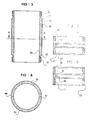
- the half-shells 20 and 21 have a semi-cylindrical internal face 24 continuous over the entire height, while their external face comprises a main median semi-cylindrical portion 25 and two end threaded portions: an upper portion 26 and a lower portion 27 The connection between these portions is effected by an upper semi-circular chamfer 28 and by a lower semi-circular chamfer 29.
- the upper ring 22 has from bottom to top: a frustoconical face 30 which is applied against the chamfer 28 of the half-shells 20 and 21 and clamps these one against the other; an internal threaded portion 31 provided to engage with the upper external threaded portion 26 of the half-shells 20 and 21; and an annular internal shoulder 32 and a threaded portion 33, intended to receive the assembly of the bearing 12 and of the membrane 13 as well as the ring 11.
- the lower ring 23 has from top to bottom: a frustoconical face 34 which is applied against the chamfer 29 of the half-shells 20 and 21 and clamps these one against the other; an internal threaded portion 35 provided for engaging with the lower external threaded portion 27 of the half-shells 20 and 21; and an annular internal shoulder 36 and an internal threaded portion 37, intended to receive the bottom 10.
- Figures 7 and 8 show alternative embodiments of the lower ring 23 without shoulder 36.
- the same threaded portion 38 serves, at the top, engaging with the lower threaded portion of the half shells 20 and 21, maintaining these against one another and, at the bottom by engaging with the bottom 10, to the fixing thereof.
- This threaded portion 38 therefore plays both the role of the threaded portion 35 and of the threaded portion 37.
- the ring 23 belongs to the bottom 10 and the same thread 39 serves both to maintain the half-shells 20 and 21 against each other and at the fixing of the bottom 10.
- the two half-shells 20 and 21 fit into each other in their main central cylindrical portion 25 as shown in FIG. 4, along the generatrixes 40, 41 of the two half-shells .
- the interlocking surface here has a V-shaped cross section.
- the two half-shells 20 and 21 are pressed against each other according to a flat surface.
Landscapes
- Immunology (AREA)
- Pathology (AREA)
- Life Sciences & Earth Sciences (AREA)
- Chemical & Material Sciences (AREA)
- Analytical Chemistry (AREA)
- Biochemistry (AREA)
- General Health & Medical Sciences (AREA)
- General Physics & Mathematics (AREA)
- Health & Medical Sciences (AREA)
- Physics & Mathematics (AREA)
- Sampling And Sample Adjustment (AREA)
- Measuring Fluid Pressure (AREA)
- Investigating Strength Of Materials By Application Of Mechanical Stress (AREA)
- Optical Measuring Cells (AREA)
- Packages (AREA)
- Devices For Use In Laboratory Experiments (AREA)
- Containers Having Bodies Formed In One Piece (AREA)
Applications Claiming Priority (2)
| Application Number | Priority Date | Filing Date | Title |
|---|---|---|---|
| FR8413538A FR2569850B1 (fr) | 1984-08-31 | 1984-08-31 | Recipient pour matiere rheologiquement evolutive, utilisable dans un consistometre d'analyse d'evolution rheologique |
| FR8413538 | 1984-08-31 |
Publications (2)
| Publication Number | Publication Date |
|---|---|
| EP0176391A1 true EP0176391A1 (de) | 1986-04-02 |
| EP0176391B1 EP0176391B1 (de) | 1989-05-10 |
Family
ID=9307370
Family Applications (1)
| Application Number | Title | Priority Date | Filing Date |
|---|---|---|---|
| EP85401652A Expired EP0176391B1 (de) | 1984-08-31 | 1985-08-19 | Gefäss für ein Instrument zur Überwachung der Entwicklung der rheologischen Eigenschaften |
Country Status (8)
| Country | Link |
|---|---|
| US (1) | US4633708A (de) |
| EP (1) | EP0176391B1 (de) |
| JP (1) | JPS61129552A (de) |
| DE (1) | DE3570128D1 (de) |
| DK (1) | DK396185A (de) |
| FR (1) | FR2569850B1 (de) |
| GB (1) | GB2163858B (de) |
| NO (1) | NO853422L (de) |
Cited By (1)
| Publication number | Priority date | Publication date | Assignee | Title |
|---|---|---|---|---|
| GB2393789A (en) * | 2002-06-27 | 2004-04-07 | Siemens Ag | Gradient coil assembly for magnetic resonance tomograph |
Families Citing this family (11)
| Publication number | Priority date | Publication date | Assignee | Title |
|---|---|---|---|---|
| CA1281915C (en) * | 1985-08-19 | 1991-03-26 | Commonwealth Scientific And Industrial Research Organization | Method and apparatus for the determination of viscosity |
| FR2594950B1 (fr) * | 1986-02-27 | 1988-05-06 | Petroles Cie Francaise | Consistometre d'analyse d'evolution rheologique, notamment utilisable sur un chantier |
| US5105655A (en) * | 1991-01-18 | 1992-04-21 | Bell Communications Research, Inc. | Rheological device for in situ measurements of photo polymerization kinetics |
| DE4239377A1 (de) * | 1992-11-24 | 1994-05-26 | Rheydt Kabelwerk Ag | Verfahren und Anordnung zur gleichzeitigen Bestimmung der Viskosität und Reaktivität eines UV-härtenden Lackes |
| US5377241A (en) * | 1993-10-12 | 1994-12-27 | General Electric Company | Effluent container |
| US5652376A (en) * | 1996-07-05 | 1997-07-29 | Dow Corning Corporation | Method of measuring yield stress |
| US6588254B1 (en) | 2002-03-29 | 2003-07-08 | Waters Investment Limited | Rotary rheometer |
| US6798099B1 (en) | 2003-07-14 | 2004-09-28 | Waters Investment Limited | Devices, systems and methods for sensing temperature of a drag cup in a rheometer motor |
| US7412877B1 (en) * | 2005-10-24 | 2008-08-19 | Hongfeng Bi | High pressure viscometer with chamber preventing sample contamination |
| US8375771B1 (en) | 2010-05-21 | 2013-02-19 | Hongfeng Bi | Viscometer for testing cement rheology |
| US8347693B2 (en) * | 2010-08-26 | 2013-01-08 | Halliburton Energy Services, Inc. | Apparatus and methods for continuous compatibility testing of subterranean fluids and their compositions under wellbore conditions |
Citations (3)
| Publication number | Priority date | Publication date | Assignee | Title |
|---|---|---|---|---|
| FR1045108A (fr) * | 1951-11-14 | 1953-11-24 | Fr De Produits Aromatiques Eta | Appareil pour la mesure de la consistance des corps pâteux |
| US2986797A (en) * | 1957-07-12 | 1961-06-06 | Irwin M Aisenberg | Mold for preparation of artificial stone test cylinders |
| DE2617078A1 (de) * | 1976-04-17 | 1977-10-27 | Ekard Bahr | Vorrichtung zum formen von beton- probekoerpern |
Family Cites Families (9)
| Publication number | Priority date | Publication date | Assignee | Title |
|---|---|---|---|---|
| US625448A (en) * | 1899-05-23 | Quick-repair device for pipes | ||
| US733995A (en) * | 1903-01-20 | 1903-07-21 | Alexander Profitlich | Pipe-coupling. |
| US3435666A (en) * | 1966-07-18 | 1969-04-01 | Champion Lab Inc | Viscometer |
| US4014393A (en) * | 1976-01-08 | 1977-03-29 | Sun Oil Company | Core receiver and method of use thereof |
| US4103943A (en) * | 1976-06-14 | 1978-08-01 | Curtin Hoyt S | Pipe coupling |
| SU960582A1 (ru) * | 1981-03-27 | 1982-09-23 | Новочеркасский Ордена Трудового Красного Знамени Политехнический Институт Им.С.Орджоникидзе | Устройство дл исследовани реологических характеристик материалов |
| FR2526946A1 (fr) * | 1982-05-11 | 1983-11-18 | Armines | Viscometre a cylindres pour mesures sous pression et temperature elevees avec prelevements d'echantillons |
| US4466276A (en) * | 1982-09-28 | 1984-08-21 | Autoclave Engineers, Inc. | Consistometer |
| US4534209A (en) * | 1983-09-15 | 1985-08-13 | Sanders Howard E | Atmospheric consistometer |
-
1984
- 1984-08-31 FR FR8413538A patent/FR2569850B1/fr not_active Expired
-
1985
- 1985-08-08 GB GB08519966A patent/GB2163858B/en not_active Expired
- 1985-08-16 US US06/766,374 patent/US4633708A/en not_active Expired - Fee Related
- 1985-08-19 EP EP85401652A patent/EP0176391B1/de not_active Expired
- 1985-08-19 DE DE8585401652T patent/DE3570128D1/de not_active Expired
- 1985-08-30 NO NO853422A patent/NO853422L/no unknown
- 1985-08-30 DK DK396185A patent/DK396185A/da unknown
- 1985-08-30 JP JP60191816A patent/JPS61129552A/ja active Pending
Patent Citations (3)
| Publication number | Priority date | Publication date | Assignee | Title |
|---|---|---|---|---|
| FR1045108A (fr) * | 1951-11-14 | 1953-11-24 | Fr De Produits Aromatiques Eta | Appareil pour la mesure de la consistance des corps pâteux |
| US2986797A (en) * | 1957-07-12 | 1961-06-06 | Irwin M Aisenberg | Mold for preparation of artificial stone test cylinders |
| DE2617078A1 (de) * | 1976-04-17 | 1977-10-27 | Ekard Bahr | Vorrichtung zum formen von beton- probekoerpern |
Non-Patent Citations (1)
| Title |
|---|
| SOVIET INVENTIONS ILLUSTRATED, semaine K30, 7 septembre 1983, abrégé no. 83-722152/30, Derwent Publications Ltd.; & SU-A-960 582 (NOVCH POLY) 25.09.1982 * |
Cited By (3)
| Publication number | Priority date | Publication date | Assignee | Title |
|---|---|---|---|---|
| GB2393789A (en) * | 2002-06-27 | 2004-04-07 | Siemens Ag | Gradient coil assembly for magnetic resonance tomograph |
| US6882152B2 (en) | 2002-06-27 | 2005-04-19 | Siemens Aktiengesellschaft | Connection device for positional fixing of a gradient coil assembly of a nuclear magnetic resonance tomograph |
| GB2393789B (en) * | 2002-06-27 | 2005-10-19 | Siemens Ag | Gradient coil assembly for magnetic resonance tomograph |
Also Published As
| Publication number | Publication date |
|---|---|
| FR2569850A1 (fr) | 1986-03-07 |
| FR2569850B1 (fr) | 1987-09-11 |
| NO853422L (no) | 1986-03-03 |
| EP0176391B1 (de) | 1989-05-10 |
| GB2163858B (en) | 1988-04-07 |
| DE3570128D1 (en) | 1989-06-15 |
| GB8519966D0 (en) | 1985-09-18 |
| US4633708A (en) | 1987-01-06 |
| DK396185A (da) | 1986-03-01 |
| GB2163858A (en) | 1986-03-05 |
| JPS61129552A (ja) | 1986-06-17 |
| DK396185D0 (da) | 1985-08-30 |
Similar Documents
| Publication | Publication Date | Title |
|---|---|---|
| EP0176391B1 (de) | Gefäss für ein Instrument zur Überwachung der Entwicklung der rheologischen Eigenschaften | |
| EP0094319A1 (de) | Rotationsrheometer zum Durchführen von Messungen unter hohen Temperatur- und Druckverhältnissen mit Probennahmevorrichtung | |
| CA1167124A (fr) | Dispositif de controle de fuite pour poste blinde a haute tension | |
| FR2965925A1 (fr) | Mesure des proprietes d'echantillons de compositions durcissantes a pression elevee | |
| FR2697119A1 (fr) | Dispositif émetteur à double raccord isolant, destiné à l'emploi dans un forage. | |
| CA1301210C (fr) | Raccordement pour tubes deformables | |
| WO2001081813A1 (fr) | Embout d'etancheite pour conduit tubulaire | |
| FR2533702A1 (fr) | Consistometre pour hautes temperatures et hautes pressions | |
| FR2593921A1 (fr) | Appareil automatique portable pour l'analyse thermodynamique de fluides souterrains | |
| FR3081964A1 (fr) | Scellage de structures creuses | |
| EP0236205B1 (de) | Konsistenzmessvorrichtung zur Bestimmung der Evolution der rheologischen Eigenschaften, insbesondere zum Gebrauch auf der Arbeitsstelle | |
| FR2871512A1 (fr) | Structure de tete de raccordement de cable | |
| CA2165733C (fr) | Dispositif modulaire pour tester des echantillons de materiaux poreux en presence de fluides polyphasiques | |
| EP0807822B1 (de) | Messung eines aus einer Oberfläche austretenden Gasstromes | |
| FR2717535A1 (fr) | Pompe verticale. | |
| FR2477238A1 (fr) | Perfectionnements aux pompes du type a piston | |
| FR2524145A1 (fr) | Procede et appareil pour controler la zone d'injection d'un agent de cimentation du sol au cours d'un processus de stabilisation d'un sol | |
| CA2791762C (fr) | Cellule et procede de test d'une composition durcissante | |
| CH631014A5 (fr) | Reacteur d'analyse et dispositif d'analyse comprenant le reacteur. | |
| FR2888308A1 (fr) | Procede pour effectuer un raccordement sur une conduite en dur se trouvant sous pression, et dispositifpour sa mise en oeuvre | |
| FR2728342A1 (fr) | Prise de pression selective pour un capteur de pression | |
| WO2024261432A1 (fr) | Instrumentation de mesure et procédé correspondant | |
| EP0271401B1 (de) | Entleerungsapparat für Laborreaktoren | |
| CA1316792C (fr) | Dispositif de couplage automatique de tuyaux | |
| FR2765302A1 (fr) | Procede et outillage de vidange de tuyauterie par percement d'un orifice dans la paroi de celle-ci |
Legal Events
| Date | Code | Title | Description |
|---|---|---|---|
| PUAI | Public reference made under article 153(3) epc to a published international application that has entered the european phase |
Free format text: ORIGINAL CODE: 0009012 |
|
| AK | Designated contracting states |
Kind code of ref document: A1 Designated state(s): BE DE IT NL |
|
| 17P | Request for examination filed |
Effective date: 19860429 |
|
| 17Q | First examination report despatched |
Effective date: 19870925 |
|
| GRAA | (expected) grant |
Free format text: ORIGINAL CODE: 0009210 |
|
| AK | Designated contracting states |
Kind code of ref document: B1 Designated state(s): BE DE IT NL |
|
| ITF | It: translation for a ep patent filed | ||
| REF | Corresponds to: |
Ref document number: 3570128 Country of ref document: DE Date of ref document: 19890615 |
|
| PGFP | Annual fee paid to national office [announced via postgrant information from national office to epo] |
Ref country code: BE Payment date: 19890828 Year of fee payment: 5 |
|
| ITTA | It: last paid annual fee | ||
| PGFP | Annual fee paid to national office [announced via postgrant information from national office to epo] |
Ref country code: NL Payment date: 19890831 Year of fee payment: 5 |
|
| PLBE | No opposition filed within time limit |
Free format text: ORIGINAL CODE: 0009261 |
|
| STAA | Information on the status of an ep patent application or granted ep patent |
Free format text: STATUS: NO OPPOSITION FILED WITHIN TIME LIMIT |
|
| PG25 | Lapsed in a contracting state [announced via postgrant information from national office to epo] |
Ref country code: DE Effective date: 19900501 |
|
| 26N | No opposition filed | ||
| PG25 | Lapsed in a contracting state [announced via postgrant information from national office to epo] |
Ref country code: BE Effective date: 19900831 |
|
| BERE | Be: lapsed |
Owner name: TOTAL CIE FRANCAISE DES PETROLES Effective date: 19900831 |
|
| PG25 | Lapsed in a contracting state [announced via postgrant information from national office to epo] |
Ref country code: NL Effective date: 19910301 |
|
| NLV4 | Nl: lapsed or anulled due to non-payment of the annual fee |