EP0176402A1 - Schalter mit Selbstunterbrechung, insbesondere Differentialschalter und Schutzschalter - Google Patents
Schalter mit Selbstunterbrechung, insbesondere Differentialschalter und Schutzschalter Download PDFInfo
- Publication number
- EP0176402A1 EP0176402A1 EP85401678A EP85401678A EP0176402A1 EP 0176402 A1 EP0176402 A1 EP 0176402A1 EP 85401678 A EP85401678 A EP 85401678A EP 85401678 A EP85401678 A EP 85401678A EP 0176402 A1 EP0176402 A1 EP 0176402A1
- Authority
- EP
- European Patent Office
- Prior art keywords
- base
- block
- contact
- cover
- support
- Prior art date
- Legal status (The legal status is an assumption and is not a legal conclusion. Google has not performed a legal analysis and makes no representation as to the accuracy of the status listed.)
- Granted
Links
- 239000011810 insulating material Substances 0.000 claims abstract description 8
- 238000000926 separation method Methods 0.000 claims abstract description 7
- 230000006835 compression Effects 0.000 claims description 6
- 238000007906 compression Methods 0.000 claims description 6
- 238000002242 deionisation method Methods 0.000 claims description 4
- BASFCYQUMIYNBI-UHFFFAOYSA-N platinum Chemical compound [Pt] BASFCYQUMIYNBI-UHFFFAOYSA-N 0.000 description 7
- 238000000429 assembly Methods 0.000 description 4
- 238000010276 construction Methods 0.000 description 3
- 238000000465 moulding Methods 0.000 description 3
- 239000006096 absorbing agent Substances 0.000 description 2
- 230000000712 assembly Effects 0.000 description 2
- 230000009977 dual effect Effects 0.000 description 2
- 239000012634 fragment Substances 0.000 description 2
- 230000035939 shock Effects 0.000 description 2
- YMHOBZXQZVXHBM-UHFFFAOYSA-N 2,5-dimethoxy-4-bromophenethylamine Chemical compound COC1=CC(CCN)=C(OC)C=C1Br YMHOBZXQZVXHBM-UHFFFAOYSA-N 0.000 description 1
- 241001415961 Gaviidae Species 0.000 description 1
- 241000287107 Passer Species 0.000 description 1
- 241000545067 Venus Species 0.000 description 1
- 239000005557 antagonist Substances 0.000 description 1
- 238000001514 detection method Methods 0.000 description 1
- 210000005069 ears Anatomy 0.000 description 1
- 239000002184 metal Substances 0.000 description 1
- 230000007935 neutral effect Effects 0.000 description 1
- 230000035945 sensitivity Effects 0.000 description 1
- 238000004804 winding Methods 0.000 description 1
Images


Classifications
-
- H—ELECTRICITY
- H01—ELECTRIC ELEMENTS
- H01H—ELECTRIC SWITCHES; RELAYS; SELECTORS; EMERGENCY PROTECTIVE DEVICES
- H01H83/00—Protective switches, e.g. circuit-breaking switches, or protective relays operated by abnormal electrical conditions otherwise than solely by excess current
- H01H83/02—Protective switches, e.g. circuit-breaking switches, or protective relays operated by abnormal electrical conditions otherwise than solely by excess current operated by earth fault currents
- H01H83/04—Protective switches, e.g. circuit-breaking switches, or protective relays operated by abnormal electrical conditions otherwise than solely by excess current operated by earth fault currents with testing means for indicating the ability of the switch or relay to function properly
-
- H—ELECTRICITY
- H01—ELECTRIC ELEMENTS
- H01H—ELECTRIC SWITCHES; RELAYS; SELECTORS; EMERGENCY PROTECTIVE DEVICES
- H01H71/00—Details of the protective switches or relays covered by groups H01H73/00 - H01H83/00
- H01H71/02—Housings; Casings; Bases; Mountings
-
- H—ELECTRICITY
- H01—ELECTRIC ELEMENTS
- H01H—ELECTRIC SWITCHES; RELAYS; SELECTORS; EMERGENCY PROTECTIVE DEVICES
- H01H71/00—Details of the protective switches or relays covered by groups H01H73/00 - H01H83/00
- H01H71/02—Housings; Casings; Bases; Mountings
- H01H71/0207—Mounting or assembling the different parts of the circuit breaker
- H01H71/0221—Majority of parts mounted on central frame or wall
-
- H—ELECTRICITY
- H01—ELECTRIC ELEMENTS
- H01H—ELECTRIC SWITCHES; RELAYS; SELECTORS; EMERGENCY PROTECTIVE DEVICES
- H01H71/00—Details of the protective switches or relays covered by groups H01H73/00 - H01H83/00
- H01H71/02—Housings; Casings; Bases; Mountings
- H01H71/0207—Mounting or assembling the different parts of the circuit breaker
- H01H2071/0242—Assembling parts of a circuit breaker by using snap mounting techniques
Definitions
- the invention relates to electrical devices with automatic cut-off, in particular differential switches, circuit-breakers or differential circuit-breakers, of the type which include a cut-off chamber (or more precisely a cut-off arc extinguishing chamber) which is closed. on all sides with the exception of an opening for the passage of at least one movable contact cooperating with a fixed contact and which contains armatures capable of creating a magnetic deionization field during the movement of separation of the contact rivets, or similar elements, fixed and mobile contacts.
- a cut-off chamber or more precisely a cut-off arc extinguishing chamber
- the invention aims to facilitate the mounting of these devices.
- the breaking chamber is arranged in an autonomous block of insulating material which is arranged so as to receive, separately or in the form of assemblies or sub-assemblies, most of the electrical and mechanical elements of the apparatus and which is associated with a base made of insulating material, the block and the base being provided with means of pivoting, guiding and mutual positioning such that the base can be approached from the block furnished with the above elements, brought to the final mounting position by pivoting relative to the block and maintained in this final position using a single screw passing through the base and tightened in the block, the assembly being completed by a cover surrounding the block and attached to the base.
- the above block thus fulfills the dual function of a mounting template and a framework of the device and it is easy to adapt and fix it to the base.
- this spring is held on the base while the corresponding movable contact is maintained on the block, so that the fixing of the base to the block using the aforementioned single screw ensures the compression of the spring and consequently the pressurization of the corresponding movable contact.
- This embodiment thus makes the fixing screw play an additional role, which simplifies the construction of the device.
- the breaking chamber is closed laterally by a cover attached to the block and a plate is used both for holding the cover on the block and for supporting a test button of known type.
- US-A-3,178,547 describes a circuit breaker, the only movable elements of the cutting mechanism of which are carried by a U-shaped piece (31) which is fixed to a base (11) by engagement of a hook (45), carried on each side by the U-shaped piece (31), in the notch a bracket (47) which is fixed by a screw (48) to the base (11).
- the U-shaped part (31) is then fixed to the base (11) by a single screw (61) which passes through this part (31) through a hole (62) and which is screwed into a nut (63) trapped in the base ( 11) during molding.
- the head of the single screw (61) can only be reached by a screwdriver from inside the base (11), which requires leaving space in the U-shaped part (31) for the passage of such a screwdriver.
- On the base (11) are directly connected cut-off chambers with extinguishing armatures (40) and an automatic overload tripping device (21, 97).
- the U-shaped part (31) thus does not fulfill the dual function of a mounting template and framework for the device.
- the U-shaped part (31) abuts (at 65) on the two above-mentioned brackets (47), which makes the fixing position uncertain.
- the invention applies particularly well to a differential switch of the kind described in French patent application FR-A-2 552 931 filed by the applicant on October 4, 1983.
- the differential switch comprises, as shown in particular in Figure 6, a toggle and snap mechanism 1, between a rotary manual actuation member or lever 2 with actuation button 2a and a holder tilting contact 3 on which is mounted at least one movable contact 4 cooperating with a fixed contact 5 and which is biased by a first spring 6 in the direction of opening or separation of the movable contact 4 relative to the fixed contact 5.
- movable contacts 4 cooperating respectively with two fixed contacts 5 and each biased by a spring 6.
- the assembly of the contact carrier 3 and of the movable contact (s) 4 is preferably arranged as described in the request for French patent FR-A-2,552,926 filed by the plaintiff on October 4, 1983, that is to say so that the same spring (s) 6 ensure (s) both the separation contacts 4 and 5 during the opening movement and the pressure of these contacts 4, 5 one on the other in the closed position.
- the mechanism 1 is capable, on the one hand, when it is tensioned, of transmitting the movement of the lever 2 to contact carrier 3 both in the opening direction and in the closing direction and, on the other hand, when the mechanism 1 is released by a relay 7 acting independently of the lever 2 on the snap of the mechanism 1, to cause the contact carrier 3 to return from its closed position to its open position.
- the mechanism 1 is arranged so as to allow the lever 2 to reset the switch, that is to say to tighten the mechanism 1 by returning it from its open position after tripping to its normal open position shown in FIG. 6, after the intervention of the relay 7 has ceased and under the action of a second spring 8 acting on this lever 2.
- the switch is housed in an insulating box which will be described in more detail below and from which the button 2a of the lever 2 emerges.
- the latching of the mechanism 1 comprises a pawl 20, of axis 21, which is biased by a third spring 22, this pawl 20 acting on the trigger lever 17.
- the axis 21 is also parallel to the axes 11, 12, 14, 15, 16 and 18 and it is linked to the housing.
- the fixed axis 18 of the trigger lever 17 is located so that, in the closed position, this trigger lever 17 is approximately parallel to the assembly of the connecting rod 10 and the connecting rod 13, this axis then being practically aligned with the axis 11 between lever 2 and connecting rod 10.
- the connecting rod 10 consists of a rectilinear rod, the two ends of which are folded at a right angle so as to respectively constitute the articulation axis 11 of the connecting rod 10 with the lever 2 and its articulation axis 14 with the connecting rod 13.
- the link 13 advantageously consists of two individual parallel links 13a and 13b so that the part 3a of the contact carrier 3, by which the articulation is made with the double link 13, is place between the two individual links 13a, 13b.
- a connecting bar 43 secures these two individual links 13a, 13b together.
- the length of the groove 19 of the trigger lever 17 is such that the articulation axis 14 between connecting rod 10 and connecting rod 13 abuts against one 23 of the longitudinal ends of this groove 19 during the resetting movement.
- the relay 7 is a permanent magnet relay, which acts by a push rod 25 on the pawl 20, which forces the pawl 20 to exert on this push rod 25 a force sufficient to overcome the action of the spring. antagonist of the permanent magnet during the resetting of the relay 7.
- a resetting spring 48 is arranged in such a way that, when the mechanism 1 is relaxed by action of the relay 7, the tension of this spring 48 is greatly increased, by a movement of separation of the two ends of this spring.
- the pawl 20 is provided with a notch 28 suitable for receiving a spout 30 carried by the trigger lever 17.
- the housing is provided with as many good inputs 32 as fixed contacts 5, which are electrically connected to these fixed contacts 5.
- each fixed contact 5 carries a contact rivet 33 which cooperates with a rivet contact 34 carried by the or each corresponding movable contact 4.
- the continuity of the electrical circuit is ensured by a braid 38 attached to the movable contact 4.
- the rivet 33 is housed in a fixed position and the rivet 34 moves in a cut-off arc chamber or, more briefly, a break 35, which is closed on all sides except for an opening 36 necessary for the movement of the movable contact 4 or more exactly of the part of this movable contact 4 which is close to its contact rivet 34.
- such an interrupting chamber 35 contains armatures 37 capable of creating a magnetic deionization field during the separation of the contact rivets 33 and 34.
- the box On the side opposite that of the input terminals 32, the box is provided with output terminals 31.
- the relay 7 is connected to a fault detection toroid 9 by a secondary winding 24.
- the switch includes a test button 39 with which a resistor 40 is associated, a flexible contact 41, a return spring 56 and two metal tabs 57 and 73.
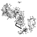
- the breaking chamber 35 is arranged in an autonomous block 26 of insulating material which is arranged so as to receive, separately or in the form of assemblies or subassemblies, most of the electrical elements and mechanical of the device and which is associated with a base 27 of insulating material.
- the block 26 and the base 27 are provided with mutual pivoting, guiding and positioning means which will be described in more detail below and such that the base 27 can be approached from the block 26 furnished with the above elements, brought to the final mounting position by pivoting relative to the block 26 (as will be explained in more detail with the aid of FIG.
- the housing which includes the block 26 and the base 27, is completed by a cover 47 surrounding the block 26 and attached to the base 27.
- the spring 6 for pressurizing the or each movable contact 4 is maintained on the base 27 (see FIG. 2) while the corresponding movable contact 4 is maintained on the block 26, so that the fixing of the base 27 on the block 26 using the single screw 44 ensures the compression of the or each spring 6 and consequently the pressurization of the corresponding movable contact 4.
- the interrupting chamber 35 is closed laterally by a cover 42 attached to the block 26 and a plate 29 is used both for holding the cover 42 on the block 26 and for supporting the test button 39. and elements associated with it.
- the aforesaid means of pivoting, guiding and positioning, which are provided between the base 27 and the block 26, are distributed, on the side of the latter, between the block 26 and the cover 42 which form a rigid assembly after plate adapter 29.
- torsion spring 8 in the handle 2 and the latter on an axis 65 molded with the block 26, placing the end of the spring 8 behind the axis 18 of the trigger lever 17, which retains the latter laterally.
- the axis 14 of the connecting rod 10 is presented in holes 66 of the connecting rod 13 and in the groove 19 of the trigger lever 17 and the axis 11 of the connecting rod 10 in an eccentric bearing 67 of the lever 2 by making turn it to obtain the center distance of the connecting rod 10.
- the armored deionization sub-assemblies 37 are also presented in the breaking chamber 35 of the block 26 as well as the fixed contacts 5 on this block 26.
- the test tab 73 is embedded on the block 26.
- the two movable contacts 4 in the housings provided for this purpose in the contact holder 3 and the relay sub-assembly is stapled to the block 26 by inserting the ears 53 fitted with shock absorbers 59 successively in openings 74 of the cover 42 and 75 of the block 26, as shown in the detail view located to the left of the top of Figure 3.
- These means advantageously include two spouts 76 and 77 provided respectively on the block 26 and the cover 42 and two corresponding notches 78 provided on the base 27, the assembly being such that, when the spouts 76, 77 are inserted respectively in the notches 78 , the assembly 26, 42 can be pivoted relative to the base 27 according to the arrow F2 in FIG. 4 or, more generally, the base 27 relative to the assembly 26, 42.
- These means further comprise flanges 79 surrounding the base 27 and suitable for receiving and guiding between them the lateral faces of the assembly 26, 42 and that of the transverse faces of this assembly which is the farthest from the spouts 76, 77.
- These means may further comprise projections and recesses which are formed on the elements 26, 42 and 27 and which engage with each other during the abovementioned pivoting movement.
Landscapes
- Breakers (AREA)
- Keying Circuit Devices (AREA)
- Driving Mechanisms And Operating Circuits Of Arc-Extinguishing High-Tension Switches (AREA)
Priority Applications (1)
| Application Number | Priority Date | Filing Date | Title |
|---|---|---|---|
| AT85401678T ATE43199T1 (de) | 1984-09-06 | 1985-08-23 | Schalter mit selbstunterbrechung, insbesondere differentialschalter und schutzschalter. |
Applications Claiming Priority (2)
| Application Number | Priority Date | Filing Date | Title |
|---|---|---|---|
| FR8413744 | 1984-09-06 | ||
| FR8413744A FR2569901B1 (fr) | 1984-09-06 | 1984-09-06 | Perfectionnements apportes aux interrupteurs a coupure automatique, notamment aux interrupteurs differentiels et disjoncteurs |
Publications (2)
| Publication Number | Publication Date |
|---|---|
| EP0176402A1 true EP0176402A1 (de) | 1986-04-02 |
| EP0176402B1 EP0176402B1 (de) | 1989-05-17 |
Family
ID=9307505
Family Applications (1)
| Application Number | Title | Priority Date | Filing Date |
|---|---|---|---|
| EP85401678A Expired EP0176402B1 (de) | 1984-09-06 | 1985-08-23 | Schalter mit Selbstunterbrechung, insbesondere Differentialschalter und Schutzschalter |
Country Status (4)
| Country | Link |
|---|---|
| EP (1) | EP0176402B1 (de) |
| AT (1) | ATE43199T1 (de) |
| DE (1) | DE3570321D1 (de) |
| FR (1) | FR2569901B1 (de) |
Cited By (3)
| Publication number | Priority date | Publication date | Assignee | Title |
|---|---|---|---|---|
| FR2626105A1 (fr) * | 1988-01-20 | 1989-07-21 | Hager Electro | Appareil de protection d'installations electriques |
| FR2686453A1 (fr) * | 1992-01-17 | 1993-07-23 | Legrand Sa | Interrupteur differentiel. |
| WO2005017935A1 (de) * | 2003-08-19 | 2005-02-24 | Moeller Gebäudeautomation KG | Prüftastermodul |
Families Citing this family (1)
| Publication number | Priority date | Publication date | Assignee | Title |
|---|---|---|---|---|
| CN103474298A (zh) * | 2013-09-30 | 2013-12-25 | 苏州路美思电气有限公司 | 一种漏电保护器 |
Citations (6)
| Publication number | Priority date | Publication date | Assignee | Title |
|---|---|---|---|---|
| US3143627A (en) * | 1960-04-15 | 1964-08-04 | Gen Electric | Multipole circuit breaker with three part insulating casing |
| US3178547A (en) * | 1961-05-10 | 1965-04-13 | Ite Circuit Breaker Ltd | Mechanism mounting device for circuit breaker |
| DE2504007A1 (de) * | 1974-02-08 | 1975-08-14 | Schrack Elektrizitaets Ag E | Fehlerstrom- bzw. fehlerspannungsschutzschalter od. dgl. |
| EP0008989A1 (de) * | 1978-09-12 | 1980-03-19 | Merlin Gerin | Elektrischer Niederspannungsschalter mit Hilfsbetätigungsbaugruppen |
| EP0017818A1 (de) * | 1979-04-12 | 1980-10-29 | Siemens Aktiengesellschaft | Fehlerstromschutzschalter mit eine Prüftaste enthaltenden Prüfeinrichtung |
| EP0099786A1 (de) * | 1982-07-12 | 1984-02-01 | Merlin Gerin | Zweipoliger Differentialschutzschalter |
-
1984
- 1984-09-06 FR FR8413744A patent/FR2569901B1/fr not_active Expired
-
1985
- 1985-08-23 DE DE8585401678T patent/DE3570321D1/de not_active Expired
- 1985-08-23 AT AT85401678T patent/ATE43199T1/de not_active IP Right Cessation
- 1985-08-23 EP EP85401678A patent/EP0176402B1/de not_active Expired
Patent Citations (6)
| Publication number | Priority date | Publication date | Assignee | Title |
|---|---|---|---|---|
| US3143627A (en) * | 1960-04-15 | 1964-08-04 | Gen Electric | Multipole circuit breaker with three part insulating casing |
| US3178547A (en) * | 1961-05-10 | 1965-04-13 | Ite Circuit Breaker Ltd | Mechanism mounting device for circuit breaker |
| DE2504007A1 (de) * | 1974-02-08 | 1975-08-14 | Schrack Elektrizitaets Ag E | Fehlerstrom- bzw. fehlerspannungsschutzschalter od. dgl. |
| EP0008989A1 (de) * | 1978-09-12 | 1980-03-19 | Merlin Gerin | Elektrischer Niederspannungsschalter mit Hilfsbetätigungsbaugruppen |
| EP0017818A1 (de) * | 1979-04-12 | 1980-10-29 | Siemens Aktiengesellschaft | Fehlerstromschutzschalter mit eine Prüftaste enthaltenden Prüfeinrichtung |
| EP0099786A1 (de) * | 1982-07-12 | 1984-02-01 | Merlin Gerin | Zweipoliger Differentialschutzschalter |
Cited By (6)
| Publication number | Priority date | Publication date | Assignee | Title |
|---|---|---|---|---|
| FR2626105A1 (fr) * | 1988-01-20 | 1989-07-21 | Hager Electro | Appareil de protection d'installations electriques |
| EP0325071A1 (de) * | 1988-01-20 | 1989-07-26 | Hager Electro S.A. | Schutzgerät für elektrische Anlagen |
| FR2686453A1 (fr) * | 1992-01-17 | 1993-07-23 | Legrand Sa | Interrupteur differentiel. |
| WO2005017935A1 (de) * | 2003-08-19 | 2005-02-24 | Moeller Gebäudeautomation KG | Prüftastermodul |
| AU2004265697B2 (en) * | 2003-08-19 | 2009-02-26 | Moeller Gebaudeautomation Gmbh | Test pushbutton module |
| CN1836302B (zh) * | 2003-08-19 | 2011-01-26 | 穆勒建筑物自动化两合公司 | 测试探针模块 |
Also Published As
| Publication number | Publication date |
|---|---|
| DE3570321D1 (en) | 1989-06-22 |
| EP0176402B1 (de) | 1989-05-17 |
| FR2569901A1 (fr) | 1986-03-07 |
| ATE43199T1 (de) | 1989-06-15 |
| FR2569901B1 (fr) | 1986-12-26 |
Similar Documents
| Publication | Publication Date | Title |
|---|---|---|
| EP0066486B1 (de) | Antriebsmechanismus für einen mehrpoligen Niederspannungs-Schutzschalter | |
| EP0410902B1 (de) | Niederspannungs-Hochstromschalter mit Mehrfachkontakten | |
| EP0570647B1 (de) | Schaltschloss für Schutzschalter und Schutzschalter, mit diesem integriert | |
| EP0342133A1 (de) | Betätigungsmechanismus für Kleinschalter mit Anzeige einer Kontaktschweissung | |
| FR2483123A1 (fr) | Disjoncteur perfectionne | |
| EP0143682B1 (de) | Selbstschalter, insbesondere Fehler- und Überstromschalter | |
| EP0176402B1 (de) | Schalter mit Selbstunterbrechung, insbesondere Differentialschalter und Schutzschalter | |
| EP0403358A1 (de) | Null- und Phasenschalter | |
| EP0206883B1 (de) | Lastschalter mit gegossenem Gehäuse | |
| EP0325501B1 (de) | Automatische Schalter, insbesondere Differential- und Schutzschaltern | |
| EP0074288B1 (de) | Automatische Begrenzungsvorrichtung für Kurzschlussströme | |
| EP2717284B1 (de) | Bedienungsvorrichtung eines elektrischen Schutzschaltgeräts, und diese umfassendes elektrisches Schutzschaltgerät | |
| CA2181188A1 (fr) | Appareil interrupteur de type contacteur-disjoncteur | |
| FR2649826A1 (fr) | Mecanisme de commande pour disjoncteur electrique | |
| EP0176455B1 (de) | Elektro-mechanische Schaltvorrichtung | |
| EP0209433B1 (de) | Kontaktträger, insbesondere für Schutzschalter | |
| FR2785085A1 (fr) | Dispositif articule pliant d'entrainement de bras de contact pour mecanisme de commande de disjoncteur, et disjoncteur comprenant un tel dispositif | |
| EP0526355B1 (de) | Einstellvorrichtung für Bimetalle eines Lastschalters | |
| EP0130208B1 (de) | Schalter mit bedientem öffnen und schliessen und mit automatischer öffnung im fall eines überstromes | |
| EP0526356A1 (de) | Anzeigevorrichtung zur Auslösung eines Schalters | |
| EP0045672B1 (de) | Kleinschalter mit Abschaltung des Nulleiters und des Phasenleiters | |
| FR2777694A1 (fr) | Bloc auxiliaire de signalisation adaptable a un disjoncteur de protection | |
| EP0054499B1 (de) | Schalter mit Trennung des Nulleiters | |
| FR2826175A1 (fr) | Appareil de commutation electrique multipolaire comportant un verrou d'enclenchement | |
| EP0008990B1 (de) | Mehrpoliger Niederspannungsschalter mit einer Einstellvorrichtung für die Welle |
Legal Events
| Date | Code | Title | Description |
|---|---|---|---|
| PUAI | Public reference made under article 153(3) epc to a published international application that has entered the european phase |
Free format text: ORIGINAL CODE: 0009012 |
|
| AK | Designated contracting states |
Kind code of ref document: A1 Designated state(s): AT BE CH DE FR GB IT LI NL |
|
| 17P | Request for examination filed |
Effective date: 19860512 |
|
| 17Q | First examination report despatched |
Effective date: 19870710 |
|
| GRAA | (expected) grant |
Free format text: ORIGINAL CODE: 0009210 |
|
| AK | Designated contracting states |
Kind code of ref document: B1 Designated state(s): AT BE CH DE FR GB IT LI NL |
|
| PG25 | Lapsed in a contracting state [announced via postgrant information from national office to epo] |
Ref country code: NL Effective date: 19890517 Ref country code: AT Effective date: 19890517 |
|
| REF | Corresponds to: |
Ref document number: 43199 Country of ref document: AT Date of ref document: 19890615 Kind code of ref document: T |
|
| REF | Corresponds to: |
Ref document number: 3570321 Country of ref document: DE Date of ref document: 19890622 |
|
| GBT | Gb: translation of ep patent filed (gb section 77(6)(a)/1977) | ||
| ITF | It: translation for a ep patent filed | ||
| NLV1 | Nl: lapsed or annulled due to failure to fulfill the requirements of art. 29p and 29m of the patents act | ||
| PLBE | No opposition filed within time limit |
Free format text: ORIGINAL CODE: 0009261 |
|
| STAA | Information on the status of an ep patent application or granted ep patent |
Free format text: STATUS: NO OPPOSITION FILED WITHIN TIME LIMIT |
|
| 26N | No opposition filed | ||
| ITTA | It: last paid annual fee | ||
| PGFP | Annual fee paid to national office [announced via postgrant information from national office to epo] |
Ref country code: GB Payment date: 19950815 Year of fee payment: 11 |
|
| PGFP | Annual fee paid to national office [announced via postgrant information from national office to epo] |
Ref country code: BE Payment date: 19950906 Year of fee payment: 11 |
|
| PGFP | Annual fee paid to national office [announced via postgrant information from national office to epo] |
Ref country code: CH Payment date: 19960715 Year of fee payment: 12 |
|
| PGFP | Annual fee paid to national office [announced via postgrant information from national office to epo] |
Ref country code: DE Payment date: 19960722 Year of fee payment: 12 |
|
| PG25 | Lapsed in a contracting state [announced via postgrant information from national office to epo] |
Ref country code: GB Effective date: 19960823 |
|
| PGFP | Annual fee paid to national office [announced via postgrant information from national office to epo] |
Ref country code: FR Payment date: 19960829 Year of fee payment: 12 |
|
| PG25 | Lapsed in a contracting state [announced via postgrant information from national office to epo] |
Ref country code: BE Effective date: 19960831 |
|
| BERE | Be: lapsed |
Owner name: S.A. HAGER ELECTRO Effective date: 19960831 |
|
| GBPC | Gb: european patent ceased through non-payment of renewal fee |
Effective date: 19960823 |
|
| PG25 | Lapsed in a contracting state [announced via postgrant information from national office to epo] |
Ref country code: LI Free format text: LAPSE BECAUSE OF NON-PAYMENT OF DUE FEES Effective date: 19970831 Ref country code: CH Free format text: LAPSE BECAUSE OF NON-PAYMENT OF DUE FEES Effective date: 19970831 |
|
| REG | Reference to a national code |
Ref country code: CH Ref legal event code: PL |
|
| PG25 | Lapsed in a contracting state [announced via postgrant information from national office to epo] |
Ref country code: FR Free format text: LAPSE BECAUSE OF NON-PAYMENT OF DUE FEES Effective date: 19980430 |
|
| PG25 | Lapsed in a contracting state [announced via postgrant information from national office to epo] |
Ref country code: DE Free format text: LAPSE BECAUSE OF NON-PAYMENT OF DUE FEES Effective date: 19980501 |
|
| REG | Reference to a national code |
Ref country code: FR Ref legal event code: ST |