EP0176455A1 - Elektro-mechanische Schaltvorrichtung - Google Patents
Elektro-mechanische Schaltvorrichtung Download PDFInfo
- Publication number
- EP0176455A1 EP0176455A1 EP85420163A EP85420163A EP0176455A1 EP 0176455 A1 EP0176455 A1 EP 0176455A1 EP 85420163 A EP85420163 A EP 85420163A EP 85420163 A EP85420163 A EP 85420163A EP 0176455 A1 EP0176455 A1 EP 0176455A1
- Authority
- EP
- European Patent Office
- Prior art keywords
- plate
- contacts
- movable
- fixed
- insulating
- Prior art date
- Legal status (The legal status is an assumption and is not a legal conclusion. Google has not performed a legal analysis and makes no representation as to the accuracy of the status listed.)
- Granted
Links
- 230000005680 Thomson effect Effects 0.000 claims abstract description 5
- 230000000694 effects Effects 0.000 claims description 7
- 238000005192 partition Methods 0.000 claims description 5
- 230000000717 retained effect Effects 0.000 claims description 5
- 238000006073 displacement reaction Methods 0.000 claims 1
- 229910052782 aluminium Inorganic materials 0.000 abstract description 2
- XAGFODPZIPBFFR-UHFFFAOYSA-N aluminium Chemical compound [Al] XAGFODPZIPBFFR-UHFFFAOYSA-N 0.000 abstract description 2
- 239000004020 conductor Substances 0.000 abstract 1
- 230000014759 maintenance of location Effects 0.000 abstract 1
- 125000006850 spacer group Chemical group 0.000 description 3
- 240000008042 Zea mays Species 0.000 description 1
- 239000006096 absorbing agent Substances 0.000 description 1
- 239000000872 buffer Substances 0.000 description 1
- 239000011810 insulating material Substances 0.000 description 1
- 238000009413 insulation Methods 0.000 description 1
- 230000007257 malfunction Effects 0.000 description 1
- 238000004519 manufacturing process Methods 0.000 description 1
- 239000000463 material Substances 0.000 description 1
- 239000000155 melt Substances 0.000 description 1
- 229910052751 metal Inorganic materials 0.000 description 1
- 239000002184 metal Substances 0.000 description 1
- 238000000926 separation method Methods 0.000 description 1
- 230000035939 shock Effects 0.000 description 1
- 238000003466 welding Methods 0.000 description 1
Images


Classifications
-
- H—ELECTRICITY
- H01—ELECTRIC ELEMENTS
- H01H—ELECTRIC SWITCHES; RELAYS; SELECTORS; EMERGENCY PROTECTIVE DEVICES
- H01H9/00—Details of switching devices, not covered by groups H01H1/00 - H01H7/00
- H01H9/30—Means for extinguishing or preventing arc between current-carrying parts
- H01H9/32—Insulating body insertable between contacts
-
- H—ELECTRICITY
- H01—ELECTRIC ELEMENTS
- H01H—ELECTRIC SWITCHES; RELAYS; SELECTORS; EMERGENCY PROTECTIVE DEVICES
- H01H3/00—Mechanisms for operating contacts
- H01H3/22—Power arrangements internal to the switch for operating the driving mechanism
- H01H3/222—Power arrangements internal to the switch for operating the driving mechanism using electrodynamic repulsion
-
- H—ELECTRICITY
- H01—ELECTRIC ELEMENTS
- H01H—ELECTRIC SWITCHES; RELAYS; SELECTORS; EMERGENCY PROTECTIVE DEVICES
- H01H9/00—Details of switching devices, not covered by groups H01H1/00 - H01H7/00
- H01H9/10—Adaptation for built-in fuses
- H01H9/106—Adaptation for built-in fuses fuse and switch being connected in parallel
Definitions
- the present invention relates to electro-mechanical devices which include a fuse cartridge and which are used in the art as switches or circuit breakers.
- Such an apparatus in principle comprises fixed contacts, one or more corresponding movable contacts, a coil capable of controlling the movement of the latter and a relatively small caliber fuse cartridge, mounted in parallel on the contact system.
- the coil When the coil is energized, it repels by Thomson effect a conductive plate secured to the movable contacts, which are then retained in the open position by engaging a comb, ratchet or the like.
- the circuit formed by the fixed and movable contacts is thus cut under a low voltage and all the current passes through the cartridge which melts with a very small delay, but sufficient for the contacts to have separated at least in large part. The rupture arc is thus established inside the cartridge where it is absorbed by the filling material thereof.
- the contact carrier insulating plate is pushed back by the plate without being linked to it while the stroke of said plate is stopped by a fixed stop which allows the plate to continue its movement by effect kinetic energy until it is retained in the open position of the movable contacts by a latching bolt system.
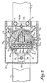
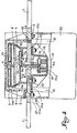
- the circuit breaker shown comprises two fixed contacts formed by the opposite ends of two bars 1 arranged coaxially with a small separation interval in the longitudinal direction.
- Bolts 2 fix these bars to an inverted upper insulating bowl 3.
- a flat circular coil 4 which bears against ribs 3a of the aforementioned bottom.
- the coil 4 is suitably coated with insulation so as to constitute a rigid part.
- a circular mobile plate 6 made of a very good conductive and relatively light metal, such as aluminum.
- the plate 6 is biased towards the bottom by a spring 7 which bears against the bottom of the housing 3, co-axially with the coil 4, but it is retained against the action of this spring by the upper edge of a vertical insulating plate 8 which, passing through the partition 5a, passes between the fixed contacts 1 to come to bear against a series of movable contacts 9 which springs 10 keep applied against said fixed contacts 1.
- the lower edge of the plate 8 is cut out from a series of notches in which the movable contacts 9 are engaged and which cause this part of the plate 8 to affect somewhat the shape of a comb.
- Each contact 9 is itself hollowed out with a notch 9a in which a tooth bottom of this profile engages, so that the contact 9 considered is retained relative to the plate 8 longitudinally and transversely. It is also provided for each contact 9 two springs 10 located on either side of the mean plane of the plate 8, these springs being engaged on centering pins 11 integral with the bottom 12a of a lower housing 12 to profile in rectangular plan, whose edges 12b, folded horizontally, are fixed to the contacts or bars 1 by bolts 13.
- the reaction of the springs 10 is sufficient to keep the plate 6 applied with a small clearance under the coil 4, despite the presence of the spring 7, the movable contacts 9 bearing against the fixed contacts 1 with the desired pressure and notwithstanding the inevitable tolerances manufacturing and assembly.
- the plate 6 When the coil 4 is traversed by a sufficiently strong current pulse, the plate 6 is pushed back down by Thomson effect against the springs 10. It lowers until it comes to abut against an inner edge 5b of the part 5, while the plate 8 continues its downward stroke under the effect of kinetic energy by moving the movable contacts 9 away from the fixed contacts 1, to come into engagement in the lowered position under the effect of a bolt 14, pushed back by a spring 15, the end of this bolt engaging in a notch 8a of the plate.
- the plate 8 is guided in its downward movement by one firstly by the partition 5a which it crosses with reduced clearance, secondly by vertical ribs 12c provided inside the housing 12 (see fig. 2 and 3).
- the bolt 14 it rests on a lowered part 5c of the partition 5a (see fig. 3) and can move under two flanges 5d thereof. It has on its underside a notch 14a, the flat bottom of which bears on a rod 16.
- the rod 17 extends parallel to the largest horizontal dimension of the lower housing 12 up to the vicinity of the wall of the upper bowl 3 so as to be connected by welding to a control lever 17 rotatably mounted on a stud 18, l 'lower end of this lever protruding below the stud to end with an operating button 19.
- the stud 18 is pressed into a lateral boss of the lower housing 12 and which is suitably notched to allow passage of the lever 17 as well as the slight angular clearance necessary for operation (fig. 2 and 3).
- the plate 8 is driven down by lowering the movable contacts 9 and it comes to engage with the bolt 14 by its notch 8a (position shown in fig . 4).
- the button 19 When it is desired to close the circuit, it suffices to operate the button 19 in the desired direction to move the rod 16 to the right in FIG. 1. This rod pushes the bolt 14 against the spring 15 and thus releases the plate 8 which rises under the effect of the springs 10.
- each bar or fixed contact 1 is screwed a vertical rod 10 which extends downwards through a tubular spacer 21, its lower end receiving a nut 22 which makes it possible to clamp against the spacer 21 one of the two knives plates of a fuse cartridge 24, which is thus bypassed on the movable contact system 9.
- the rods 20 and the spacers 21 are fairly long so that the cartridge fits easily under the lower case 12.
- an insulating lower cover 25 capable of enclosing the cartridge.
- This cover made of insulating material, is articulated at the edge of the housing 12 by means of an axis 26. Its end opposite this axis has a flange 25a which engages in an appropriate retaining part very schematically indicated in mixed lines in 27.
- the circuit breaker just described is completely enclosed and therefore poses no danger. However, it remains perfectly accessible, especially for changing the cartridge after switching off. Thanks to the insulating plate 8 which is inserted between the fixed contacts 1 at the time of opening, any risk of direct arcing between arcs is eliminated and moreover these contacts 1 can be extremely close together, which reduces the dimensions and mass of the movable contacts 9, thereby speeding up operation.
Landscapes
- Breakers (AREA)
- Arc-Extinguishing Devices That Are Switches (AREA)
- Fuses (AREA)
Applications Claiming Priority (2)
| Application Number | Priority Date | Filing Date | Title |
|---|---|---|---|
| FR8413958A FR2570217B1 (fr) | 1984-09-07 | 1984-09-07 | Dispositif de coupe-circuit electromecanique |
| FR8413958 | 1984-09-07 |
Publications (2)
| Publication Number | Publication Date |
|---|---|
| EP0176455A1 true EP0176455A1 (de) | 1986-04-02 |
| EP0176455B1 EP0176455B1 (de) | 1988-08-10 |
Family
ID=9307640
Family Applications (1)
| Application Number | Title | Priority Date | Filing Date |
|---|---|---|---|
| EP85420163A Expired EP0176455B1 (de) | 1984-09-07 | 1985-09-06 | Elektro-mechanische Schaltvorrichtung |
Country Status (4)
| Country | Link |
|---|---|
| US (1) | US4631508A (de) |
| EP (1) | EP0176455B1 (de) |
| DE (1) | DE3564356D1 (de) |
| FR (1) | FR2570217B1 (de) |
Cited By (1)
| Publication number | Priority date | Publication date | Assignee | Title |
|---|---|---|---|---|
| EP0348584A1 (de) * | 1988-06-27 | 1990-01-03 | S.A. Acec Transport | Durch einen Auslösekreis betätigter Schnellschalter |
Families Citing this family (6)
| Publication number | Priority date | Publication date | Assignee | Title |
|---|---|---|---|---|
| FR2621170A1 (fr) * | 1987-09-25 | 1989-03-31 | Merlin Gerin | Disjoncteur-limiteur |
| SE9900852D0 (sv) | 1999-03-08 | 1999-03-08 | Secheron Sa | An electrical coil module, an electrical coil comprising such modules, an actuation mechanism including such a coil and a circuit breaker comprising such an actuation mechanism |
| FR2891397B1 (fr) * | 2005-09-23 | 2007-10-26 | Schneider Electric Ind Sas | Dispositif de commutation comprenant un mecanisme d'actionnement ultra-rapide |
| WO2011144256A1 (en) * | 2010-05-21 | 2011-11-24 | Abb Research Ltd | An actuator, circuit breaker and method therefor |
| EP3146548B1 (de) | 2014-05-19 | 2018-12-05 | ABB Schweiz AG | Elektrisches strombegrenzendes hochgeschwindigkeitsschaltgerät |
| CN117334541B (zh) * | 2023-12-01 | 2024-03-19 | 杭州高特电子设备股份有限公司 | 一种主动断开熔断器及断开方法 |
Citations (5)
| Publication number | Priority date | Publication date | Assignee | Title |
|---|---|---|---|---|
| FR1146430A (fr) * | 1955-04-06 | 1957-11-12 | Siemens Ag | Appareil de branchement, en particulier pour interrupteurs électriques |
| CH379599A (de) * | 1959-02-17 | 1964-07-15 | Siemens Ag | Starkstromschalteinrichtung für schnelles Ausschalten |
| FR1454452A (fr) * | 1965-08-04 | 1966-02-11 | Comp Generale Electricite | Court-circuiteur |
| US4370636A (en) * | 1981-04-03 | 1983-01-25 | General Electric Company | Electromagnetic dual break contactor |
| FR2533066A1 (fr) * | 1982-09-10 | 1984-03-16 | Naimer Hubert | Dispositif de contact |
Family Cites Families (1)
| Publication number | Priority date | Publication date | Assignee | Title |
|---|---|---|---|---|
| FR2454174A1 (fr) * | 1979-04-09 | 1980-11-07 | Merlin Gerin | Contacteur a commande d'ouverture rapide sur defaut |
-
1984
- 1984-09-07 FR FR8413958A patent/FR2570217B1/fr not_active Expired
-
1985
- 1985-09-06 EP EP85420163A patent/EP0176455B1/de not_active Expired
- 1985-09-06 DE DE8585420163T patent/DE3564356D1/de not_active Expired
- 1985-09-20 US US06/778,470 patent/US4631508A/en not_active Expired - Fee Related
Patent Citations (5)
| Publication number | Priority date | Publication date | Assignee | Title |
|---|---|---|---|---|
| FR1146430A (fr) * | 1955-04-06 | 1957-11-12 | Siemens Ag | Appareil de branchement, en particulier pour interrupteurs électriques |
| CH379599A (de) * | 1959-02-17 | 1964-07-15 | Siemens Ag | Starkstromschalteinrichtung für schnelles Ausschalten |
| FR1454452A (fr) * | 1965-08-04 | 1966-02-11 | Comp Generale Electricite | Court-circuiteur |
| US4370636A (en) * | 1981-04-03 | 1983-01-25 | General Electric Company | Electromagnetic dual break contactor |
| FR2533066A1 (fr) * | 1982-09-10 | 1984-03-16 | Naimer Hubert | Dispositif de contact |
Cited By (1)
| Publication number | Priority date | Publication date | Assignee | Title |
|---|---|---|---|---|
| EP0348584A1 (de) * | 1988-06-27 | 1990-01-03 | S.A. Acec Transport | Durch einen Auslösekreis betätigter Schnellschalter |
Also Published As
| Publication number | Publication date |
|---|---|
| FR2570217A1 (fr) | 1986-03-14 |
| US4631508A (en) | 1986-12-23 |
| DE3564356D1 (en) | 1988-09-15 |
| EP0176455B1 (de) | 1988-08-10 |
| FR2570217B1 (fr) | 1988-05-27 |
Similar Documents
| Publication | Publication Date | Title |
|---|---|---|
| EP0410902B1 (de) | Niederspannungs-Hochstromschalter mit Mehrfachkontakten | |
| EP0066486B1 (de) | Antriebsmechanismus für einen mehrpoligen Niederspannungs-Schutzschalter | |
| EP0570647B1 (de) | Schaltschloss für Schutzschalter und Schutzschalter, mit diesem integriert | |
| FR2669463A1 (fr) | Interrupteur de protection. | |
| EP0176455B1 (de) | Elektro-mechanische Schaltvorrichtung | |
| EP0074288B1 (de) | Automatische Begrenzungsvorrichtung für Kurzschlussströme | |
| EP0325501A1 (de) | Automatische Schalter, insbesondere Differential- und Schutzschaltern | |
| FR2521773A1 (fr) | Petit contacteur equipe d'un sous-ensemble d'interrupteurs auxiliaires amovible | |
| FR2907270A1 (fr) | Appareil electrique,destine a etre fixe sur un rail support, et procede de montage correspondant | |
| EP2398029B1 (de) | Schalter mit monostabiler Bedienung und bistabilem Kontakt | |
| FR2718283A1 (fr) | Disjoncteur pour fortes intensités, comportant un dispositif d'interface opérateur/moteur et dispositif d'interface opérateur/moteur pour un tel disjoncteur. | |
| EP0105817B1 (de) | Drehende Schaltvorrichtung mit Druckknöpfen und Selbstreinigung der Kontakte | |
| FR2527379A1 (fr) | Dispositif de connexion pour commutateur electrique | |
| EP0993012B1 (de) | Einbau des Einschaltwiderstandes für Hochspannungsanlage | |
| EP0176402B1 (de) | Schalter mit Selbstunterbrechung, insbesondere Differentialschalter und Schutzschalter | |
| EP0403329A1 (de) | Schalter mit automatischer Auslösung, insbesondere Schutzschalter und Fehlerstromschutzschalter | |
| EP0773572A1 (de) | Elektrisches Gerät mit Schnappeinschaltung | |
| EP0008990B1 (de) | Mehrpoliger Niederspannungsschalter mit einer Einstellvorrichtung für die Welle | |
| EP0704872A1 (de) | Mittelspannungsschalter oder Schutzschalter | |
| EP0037295B1 (de) | Schnellschalter mit einer Vorrichtung zur Stossicherung | |
| FR2614728A1 (fr) | Porte-contacts a deplacement en translation pour appareil interrupteur de protection | |
| EP2442337B1 (de) | Schlüsselkontaktvorrichtung | |
| FR2607319A1 (fr) | Telerupteur comportant un inverseur auxiliaire sur son circuit de commande | |
| FR2694838A1 (fr) | Perfectionnement aux dispositifs de coupure de ligne électrique comportant des moyens de confinement d'amorçage d'arc électrique. | |
| FR2600829A1 (fr) | Pince de contact electrique a serrage automatique notamment pour la mise a la terre des conducteurs electriques aeriens |
Legal Events
| Date | Code | Title | Description |
|---|---|---|---|
| PUAI | Public reference made under article 153(3) epc to a published international application that has entered the european phase |
Free format text: ORIGINAL CODE: 0009012 |
|
| AK | Designated contracting states |
Kind code of ref document: A1 Designated state(s): CH DE GB IT LI SE |
|
| 17P | Request for examination filed |
Effective date: 19860626 |
|
| 17Q | First examination report despatched |
Effective date: 19871120 |
|
| GRAA | (expected) grant |
Free format text: ORIGINAL CODE: 0009210 |
|
| AK | Designated contracting states |
Kind code of ref document: B1 Designated state(s): CH DE GB IT LI SE |
|
| REF | Corresponds to: |
Ref document number: 3564356 Country of ref document: DE Date of ref document: 19880915 |
|
| GBT | Gb: translation of ep patent filed (gb section 77(6)(a)/1977) | ||
| ITF | It: translation for a ep patent filed | ||
| PLBE | No opposition filed within time limit |
Free format text: ORIGINAL CODE: 0009261 |
|
| STAA | Information on the status of an ep patent application or granted ep patent |
Free format text: STATUS: NO OPPOSITION FILED WITHIN TIME LIMIT |
|
| 26N | No opposition filed | ||
| PGFP | Annual fee paid to national office [announced via postgrant information from national office to epo] |
Ref country code: SE Payment date: 19900830 Year of fee payment: 6 Ref country code: GB Payment date: 19900830 Year of fee payment: 6 Ref country code: DE Payment date: 19900830 Year of fee payment: 6 |
|
| PGFP | Annual fee paid to national office [announced via postgrant information from national office to epo] |
Ref country code: CH Payment date: 19900910 Year of fee payment: 6 |
|
| ITTA | It: last paid annual fee | ||
| PG25 | Lapsed in a contracting state [announced via postgrant information from national office to epo] |
Ref country code: GB Effective date: 19910906 |
|
| PG25 | Lapsed in a contracting state [announced via postgrant information from national office to epo] |
Ref country code: SE Effective date: 19910907 |
|
| PG25 | Lapsed in a contracting state [announced via postgrant information from national office to epo] |
Ref country code: LI Effective date: 19910930 Ref country code: CH Effective date: 19910930 |
|
| GBPC | Gb: european patent ceased through non-payment of renewal fee | ||
| REG | Reference to a national code |
Ref country code: CH Ref legal event code: PL |
|
| PG25 | Lapsed in a contracting state [announced via postgrant information from national office to epo] |
Ref country code: DE Effective date: 19920602 |
|
| EUG | Se: european patent has lapsed |
Ref document number: 85420163.9 Effective date: 19920408 |