EP0176705A2 - Fast breeder reactor - Google Patents
Fast breeder reactor Download PDFInfo
- Publication number
- EP0176705A2 EP0176705A2 EP85109916A EP85109916A EP0176705A2 EP 0176705 A2 EP0176705 A2 EP 0176705A2 EP 85109916 A EP85109916 A EP 85109916A EP 85109916 A EP85109916 A EP 85109916A EP 0176705 A2 EP0176705 A2 EP 0176705A2
- Authority
- EP
- European Patent Office
- Prior art keywords
- cooling system
- breeder reactor
- primary
- fast breeder
- channel
- Prior art date
- Legal status (The legal status is an assumption and is not a legal conclusion. Google has not performed a legal analysis and makes no representation as to the accuracy of the status listed.)
- Granted
Links
Images



Classifications
-
- G—PHYSICS
- G21—NUCLEAR PHYSICS; NUCLEAR ENGINEERING
- G21C—NUCLEAR REACTORS
- G21C15/00—Cooling arrangements within the pressure vessel containing the core; Selection of specific coolants
- G21C15/24—Promoting flow of the coolant
- G21C15/243—Promoting flow of the coolant for liquids
- G21C15/247—Promoting flow of the coolant for liquids for liquid metals
-
- G—PHYSICS
- G21—NUCLEAR PHYSICS; NUCLEAR ENGINEERING
- G21C—NUCLEAR REACTORS
- G21C1/00—Reactor types
- G21C1/02—Fast fission reactors, i.e. reactors not using a moderator ; Metal cooled reactors; Fast breeders
- G21C1/03—Fast fission reactors, i.e. reactors not using a moderator ; Metal cooled reactors; Fast breeders cooled by a coolant not essentially pressurised, e.g. pool-type reactors
-
- Y—GENERAL TAGGING OF NEW TECHNOLOGICAL DEVELOPMENTS; GENERAL TAGGING OF CROSS-SECTIONAL TECHNOLOGIES SPANNING OVER SEVERAL SECTIONS OF THE IPC; TECHNICAL SUBJECTS COVERED BY FORMER USPC CROSS-REFERENCE ART COLLECTIONS [XRACs] AND DIGESTS
- Y02—TECHNOLOGIES OR APPLICATIONS FOR MITIGATION OR ADAPTATION AGAINST CLIMATE CHANGE
- Y02E—REDUCTION OF GREENHOUSE GAS [GHG] EMISSIONS, RELATED TO ENERGY GENERATION, TRANSMISSION OR DISTRIBUTION
- Y02E30/00—Energy generation of nuclear origin
- Y02E30/30—Nuclear fission reactors
Definitions
- the loop type builds a system by connecting the cooling systems and the components by means of pipes.
- the tank type is a system wherein primary cooling system equipments such as the reactor core,primary system pumps and intermediate heat exchangers are contained within a main vessel in the shape of a large tank and wherein the coolant of the primary system for directly cooling the reactor core circulates within the tank and transmits the heat outside the reactor from the secondary sides of the intermediate heat exchangers. Since the present invention is more effective when applied to the tank type of the latter, the FBR of the tank type will be principally described by way of example.
- the system of the tank type FBR comprises in combination a primary cooling system 5, a secondary cooling system 8 and a steam system 13.
- the secondary cooling system 8 operates so that sodium liquid discharged from a steam generator 7 may be brought into the intermediate heat exchanger 3 by a secondary system pump 6 and that sodium liquid which has become a higher temperature upon receiving the heat of the primary cooling system via the intermediate heat exchanger 3 and which is discharged from the intermediate heat exchanger 3 may be brought back into the steam generator 7.
- a secondary cooling system pipe 29a is connected to the inlet header tube 29, while one end of a secondary cooling system pipe 28a is similarly connected to the outlet header tube 28.
- the other end of the pipe 29a is connected to the discharge port side of a pump 6 in a secondary cooling system 8, and the other end of the pipe 28a to a steam generator 7.
- the secondary cooling system 8 and a water/steam system 13 are identical in construction to those of the prior-art example, and in Fig. 3, the same components as in the prior-art example are assigned the same symbols.
- This annular current 34 corresponds to the current I in Fig. 5.
- the sodium liquid 36 of the primary cooling system which has been introduced into the primary cooling system channel 31 from the entrances 25 upon undergoing the current 34and the magnetic flux 33, flows as a stream in a downward vertical (thrust) direction.
- the force of the flow corresponds to the force P in Fig. 5.
- Both the sodium liquids 35 and 36 can be caused to flow by only one pump 6 while exchanging heat through the heat transfer plate 30. In this way, the generated current I becomes the annular current 34 efficiently passing through the respective channels 31 and 32, so that efficient flowing states of the sodium liquids are attained.
- outer magnets 23a and 23b are comprised besides the outer magnet 23, and the whole outer magnet assembly is constructed as a three-stage arrangement in which the respective magnets 23, 23a and 23b are arrayed in series.
- the magnetic poles of the respective stages of the magnets are arrayed in the order of N - S, S - N and N - S, whereby no magnetism is canceled. Accordingly, the greatest plus and minus magnitudes of the magnetic flux 33 appear at the joint parts of the adjacent stages.
- the intermediate heat exchanger 40 performs the heat exchange function and the pumping function of the primary cooling system, and hence, the pump of the primary cooling system can be omitted.
- this brings forth the effects that the reliability of the system is remarkably enhanced and that both the functions can be gathered up with a good space factor.
- a primary system pump within a tank reactor can be dispensed with, so that the factors of mechanical faults attributed to machine wear, vibrations, thermal deformation,etc. or electrical faults attributed to dielectric breakdown, etc. are all eliminated to markedly enhance the reliability of a system.
- an intermediate heat exchanger can be used for both a heat exchange function and a pumping function, which can contribute to the miniaturization of a main vessel and the simplification of a primary cooling system.
- the flow rate control of the primary cooling system can be performed by changing the flow rate of a secondary cooling system, the controllability of an FBR plant is enhanced advantageously.
Landscapes
- Physics & Mathematics (AREA)
- Engineering & Computer Science (AREA)
- Plasma & Fusion (AREA)
- General Engineering & Computer Science (AREA)
- High Energy & Nuclear Physics (AREA)
- Heat-Exchange Devices With Radiators And Conduit Assemblies (AREA)
Abstract
Description
- This invention relates to a fast breeder reactor, and more particularly to an intermediate heat exchanger which is installed in the reactor.
- Fast breeder reactors (hereinbelow, simply termed "FBRs") which employ liquid metal, especially sodium, as a coolant include the loop type and the tank type. Each of the types is constructed of a primary cooling system which directly cools the heat of a reactor core generated by nuclear fission, a secondary cooling system which transports heat out of the reactor through an intermediate heat exchanger, a steam generator which produces superheated vapor for driving a turbine generator, and a cooling system such as a water/steam system.
- The loop type builds a system by connecting the cooling systems and the components by means of pipes. In contrast, the tank type is a system wherein primary cooling system equipments such as the reactor core,primary system pumps and intermediate heat exchangers are contained within a main vessel in the shape of a large tank and wherein the coolant of the primary system for directly cooling the reactor core circulates within the tank and transmits the heat outside the reactor from the secondary sides of the intermediate heat exchangers. Since the present invention is more effective when applied to the tank type of the latter, the FBR of the tank type will be principally described by way of example.
- Fig. 1 is a diagram showing the whole system of a tank type FBR.
- The system of the tank type FBR comprises in combination a
primary cooling system 5, asecondary cooling system 8 and asteam system 13. - Most of the
primary cooling system 5 is contained within the tank-shapedmain vessel 4 of the FBR. - Fig. 2 is a structural diagram of the
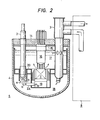
primary cooling system 5 mentioned above. Theprimary cooling system 5 is generally received in the tank-reactormain vessel 4. Located substantially centrally is areactor core 1 under which a high-pressure plenum chamber 19 exists, each and theoutlet pipe 2A ofprimary system pump 2 is / connected to this high-pressure plenum chamber 19. The tank-reactormain vessel 4 is divided into anupper plenum portion 17 and alower plenum portion 18 by apartition wall structure 20, and eachintermediate heat exchanger 3 is arranged penetrating thepartition wall structure 20. Located directly above thereactor core 1 is a reactor upper-portion mechanism 16 which has a drive mechanism for fuel replacement, control rods, etc. The top of the tank-reactormain vessel 4 is provided with a lid which is called aroof slab 14, and which supports the aforementioned components such as theintermediate heat exchangers 3, reactor upper-portion mechanism 16 andprimary system pumps 2 in suspending fashion. The lower surface of theroof slab 14 is provided withthermal shield plates 15 in order to prevent radiant heat from high-temperature sodium. A construction similar to that explained above is described in Japanese Patent Application Laying-open No. 49-125797. For example, in case of "Super Phenix" of 1200 MWe class, the diameter of a tank reactor is about 21 m., and theintermediate heat exchangers 3 numbering eight and theprimary system pumps 2 of the mechanical type numbering four are arranged around the core of the reactor. In the nuclear reactor structure thus constructed, sodium in theprimary cooling system 5 is heated by thereactor core 1, enters eachintermediate heat exchanger 3 at theupper plenum 17, delivers heat to sodium in thesecondary cooling system 8 and is thereafter released to thelower plenum 18. The suction portion of eachprimary system pump 2 is open into thelower plenum 18, so that the sodium having become a lower temperature in consequence of the delivery of the heat as stated above is introduced as indicated by arrows a and is forcibly fed into the high-pressure plenum chamber 19 again as indicated by arrows b. Accordingly, the primary system sodium is circulated in this manner while repeating the heating and cooling of the interior of the tank-reactormain vessel 4. - As shown in Fig. 1, the
secondary cooling system 8 operates so that sodium liquid discharged from asteam generator 7 may be brought into theintermediate heat exchanger 3 by asecondary system pump 6 and that sodium liquid which has become a higher temperature upon receiving the heat of the primary cooling system via theintermediate heat exchanger 3 and which is discharged from theintermediate heat exchanger 3 may be brought back into thesteam generator 7. - The
steam system 13 feeds thesteam generator 7 with water in asteam condenser 12 by means of afeed water pump 9 and applies the heat of the sodium liquid of thesecondary cooling system 8 so as to turn the water into steam, and it sends the steam from thesteam generator 7 to aturbine 10 so as to rotate theturbine 10 and then rotate anelectric generator 11 interlocking with thisturbine 10, thereby to produce electric power, whereupon the steam having passed through theturbine 10 is turned by thecondenser 12 into water which is circulated through the steam system again. - In this manner, the cooling systems of the whole FBR is constructed. Usually, each of the cooling systems from the secondary system to the turbine is divided into a plurality of loops from the viewpoints of a heat exchange efficiency, a plant controllability, etc. In the case of the Super Phenix, each of the
secondary system 8 and the water/steam system 13 is constructed in four loops for the eightintermediate heat exchangers 3. - The most important reason why the
secondary cooling system 8 is interposed between theprimary cooling system 5 and the water/steam system 13, is the consideration of safety according to which to the end of preventing the exposure of the exterior to sodium that has been activated by absorbing fast neutrons in thereactor core 1, heat is once transferred to the non-radioactive sodium within thesecondary cooling system 8 through theintermediate heat exchanger 3 and is thereafter transported to the side of thesteam generator 7, whereby the activated sodium within theprimary cooling system 5 is prevented from coming out of themain vessel 4. - The sodium liquid circulating within the
primary cooling system 5 is activated during the circulation and accumulates therein 22 Na of long half life, so that repair and inspection become difficult. Accordingly, a high reliability is required of the equipments in the primary cooling system of the FBR. Nevertheless, the mechanical pump is a rotary machine, which is an equipment being least immune to thermal deformation, vibrations etc. and having the highest potential of trouble. A concrete study on introducing an electromagnetic pump instead of the mechanical pump has recently been made in France. In case of assembling the electromagnetic pump into theprimary cooling system 5, the mechanical fault rate of the pump lowers. Since, however, the environment of use of the electromagnetic pump is the depths of the liquid of high-temperature sodium,the electrical durabilities of an exciting coil, feeding electric wires, etc., the sodium proof of an insulator, and so forth arise as new problems. Furthermore, according to the contents of the concrete study mentioned above, merely the intermediate heat exchanger and the electromagnetic pump are coupled in series. Therefore, the space factor of the components in the series direction is inferior, and the length in the series direction becomes too great, so that the main vessel of the FBR tends to become large in size. - An object of this invention is to provide an FBR cooling system of superior space factor.
- In order to accomplish the object, the present invention provides a fast breeder reactor having an intermediate heat exchanger into which a liquid metal in one of both cooling systems of a primary cooling system and a secondary cooling system of the fast breeder reactor is introduced as a primary fluid and a liquid metal in the other cooling system as a secondary fluid, the secondary cooling system being furnished with a pump which causes the liquid metal in this secondary cooling system to flow; characterized in that said intermediate heat exchanger is constructed of a magnetic field generator, and a channel which is so formed that its flow direction is set to a direction traversing a magnetic flux produced by said magnetic field generator, said channel being partitioned by an electrically-conductive heat transfer plate to define a primary cooling system channel through which said primary fluid is passed and a secondary cooling system channel through which said secondary fluid is passed.
-
- Fig. 1 shows a prior-art example and is a schematic flow diagram of the cooling systems of a tank type fast breeder reactor.
- Fig. 2 shows a prior-art example and is an enlarged view of the primary cooling system shown in Fig. 1.
- Fig. 3 shows a first embodiment of the present invention and is a flow diagram of the cooling systems of a tank type fast breeder reactor.
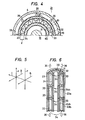
- Fig. 4 is a sectional view taken and seen along arrows I - I in Fig. 3 and illustrates only a half because the corresponding section is horizontally symmetric.
- Fig. 5 is a vector diagram for explaining the fundamental principle of the present invention.
- Fig. 6 is an explanatory diagram showing the vectorial relations of Fig. 5 in conformity with the structure of Fig. 3.
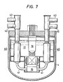
- Fig. 7 shows a second embodiment of the present invention and is a sectional view illustrative of the construction of the primary cooling system of a tank type fast breeder reactor.
- Fig. 8 is a vertical sectional view of an intermediate heat exchanger shown in Fig. 7.
- Fig. 9 is a sectional view taken and seen along arrows II - II in Fig. 8.
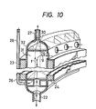
- Fig. 10 is a schematic perspective view showing a section of an intermediate heat exchanger in Fig. 3.
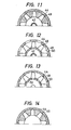
- Fig. 11 is a sectional view taken along III - III in Fig. 8.
- Fig. 12 is a sectional view taken along IV - IV in Fig. 8.
- Fig. 13 is a sectional view taken along V - V in Fig. 8.
- Fig. 14 is a sectional view taken along VI - VI in Fig. 8.
- The nuclear reactor structure of an FBR according to a first embodiment of the present invention shown in Figs. 3 and 4 is as stated below.
- A tank-shaped
main vessel 4 is covered with aroof slab 14. Areactor core 1 is arranged under a reactor upper-portion mechanism 16 which is supported by theroof slab 14. Thisreactor core 1 is supported by apartition wall 20 which is fitted in themain vessel 4. Thepartition wall 20 divides the interior of themain vessel 4 into anupper plenum 17 and alower plenum 18. Inside thelower plenum 18, a high-pressure plenum chamber 19 is formed which communicates with thereactor core 1 fluid-wise. - Inside the
upper plenum 17, an electromagnetic flow coupler typeintermediate heat exchanger 21 which is annular is formed in a manner to surround the reactor upper-portion mechanism 16. - The structure of the electromagnetic flow coupler type
intermediate heat exchanger 21 is as follows. It has a cylindrical innermagnetic material 24 whose surfaces are clad withstainless steel plates 60 durable against sodium, and a cylindricalouter magnet 23 which is clad withstainless steel plates 61 and which is arranged so as to surround the outer side of the innermagnetic material 24. In arranging themagnet 23 and themagnetic material 24, their polarities are conformed so that a magnetic flux may have a direction traversing an annular space I developing between themagnet 23 and themagnetic material 24. Since both themagnet 23 and themagnetic material 24 are used in a high-temperature sodium liquid, they are made of a substance which has good high-temperature magnetic characteristics, for example, a magnetic substance whose Curie point is high. In addition, both themagnet 23 and themagnetic material 24 are of a material such as alnico V, and themagnet 23 is a permanent magnet. As the magnetic substance of this magnet, one of the best possible high-temperature characteristics is selected as stated before. Themagnet 23 and themagnetic material 24 constitute a magnetic field generator. Inside the annular space i appearing between themagnet 23 and themagnetic material 24, a stainless steel plate which is electrically conductive and which is durable against sodium is arranged as aheat transfer plate 30 in a corrugated state as shown in Fig. 4. Both the ends of theheat transfer plate 30 are welded to each other. Thisheat transfer plate 30 is partly welded to the stainless steel plates which clothe themagnet 23 and themagnetic material 24. Owing to the provision of theheat transfer plate 30, the annular space I formed between themagnet 23 and themagnetic material 24 is divided into a primarycooling system channel 31 which faces theinner magnet 24 and a secondarycooling system channel 32 which faces theouter magnet 23.Inlet pipes 26, which are disposed in a manner to communicate with the secondarycooling system channel 32 fluid-wise and to be shut off from the primarycooling system channel 31, penetrate theroof slab 14 and are communicatingly connected to aninlet header tube 29 which is a ring-shaped bent tube.Outlet pipes 27, which are disposed in a manner to communicate with the secondarycooling system channel 32 fluid-wise and to be shut off from the primarycooling system channel 31, penetrate theroof slab 14 and are communicatingly connected to an outlet header tube 28 which is a ring-shaped bent tube.Entrances 25, which are open to theupper plenum 17, communicate with only theprimary one 31 of the primary and secondarycooling system channels fluid exit pipes 22 communicate with only theprimary one 31 of the primary and secondarycooling system channels pressure plenum chamber 19. The above is the structure of the electromagnetic flow coupler typeintermediate heat exchanger 21. - One end of a secondary
cooling system pipe 29a is connected to theinlet header tube 29, while one end of a secondary cooling system pipe 28a is similarly connected to the outlet header tube 28. The other end of thepipe 29a is connected to the discharge port side of apump 6 in asecondary cooling system 8, and the other end of the pipe 28a to asteam generator 7. Thesecondary cooling system 8 and a water/steam system 13 are identical in construction to those of the prior-art example, and in Fig. 3, the same components as in the prior-art example are assigned the same symbols. - In the FBR of the above structure, when sodium liquid in the
secondary cooling system 8 is circulated in the direction of an arrow e by a pumping force based on thepump 6, it enters theinlet header tube 29 from thepipe 29a and flows into therespective inlet pipes 26 in branched fashion. The branch streams rise within the secondarycooling system channel 32 along theheat transfer plate 30 as indicated by an arrow f in Fig. 10, flow out to therespective outlet pipes 27 and join within the outlet header tube 28. The resulting stream is sent into thesteam generator 7 through the tube 28, and it is drawn by suction and then circulated by means of thepump 6 again. Upon the occurrence of the circulation of the sodium liquid in thesecondary cooling system 8, when this sodium liquid rises in the secondarycooling system channel 32, it induces the action of giving a downward flowing force to sodium liquid in the primarycooling system channel 31. This action will be described in detail later. For that reason, sodium liquid in theupper plenum 17 inside themain vessel 4 flows downwards within the primarycooling system channel 31 from theentrances 25 as indicated by an arrow I in Fig. 10 and passes through the interiors of the primaryfluid exit pipes 22 until it is discharged into the high-pressure plenum chamber 19. It passes through thereactor core 1 and is heated, whereupon it is returned into theupper plenum 17. While the sodium liquid in themain vessel 4 and the sodium liquid in thesecondary cooling system 8 are flowing in the upward and downward directions opposite to each other in contact with theheat transfer plate 30, the latter receives heat from the former through theheat transfer plate 30 and transports the heat to thesteam generator 7. The heat transported to thesteam generator 7 is consumed by the water/steam system 13 in order to produce high-pressure steam, which is used as energy for rotating theturbine 10 of an electric generator.11. - Next, the action of affording the flowing force to the sodium liquid in the primary
cooling system channel 31 will be explained. - Fig. 5 illustrates the operating principle of an electromagnetic flow coupler. The sodium liquids of the primary cooling system and the secondary cooling system exist as electric conductors within the magnetic flux B generated by the
magnet 23 and themagnetic material 24. When the force F of thepump 6, for example, is applied to one conductor (the sodium liquid of the secondary cooling system), a current I is generated in the conductor (the sodium liquid of the secondary cooling system) in a direction which is orthogonal to both the magnetic flux B and the force F. This phenomenon corresponds to a power generation portion based on the right-hand rule. Meanwhile, when the other conductor (the sodium liquid in the primary cooling system channel 31) having received the current I is subjected to the same magnetic flux B, an electromotive action conforming to the lefthand rule develops this time, and the other conductor receives a force P in a direction which is orthogonal to both the magnetic flux B and the current I. In consequence, the other of the respective conductors in the two channels existing within the identical magnetic flux B undergoes the flowing force being the force P in the direction opposite to that of the driving force owing to the pump. - It is Fig. 6 that elucidates the operation of the electromagnetic flow coupler type
intermediate heat exchanger 21 based on this principle. - Referring to Fig. 6, a
magnetic flux 33 corresponding to the magnetic flux B in Fig. 5 is generated by theouter magnet 23 and the innermagnetic material 24. Thus, themagnet 23 and themagnetic material 24 are utilized as the magnetic field generator for producing themagnetic flux 33. Themagnetic flux 33 has parts extending in a direction in which the annular space i defined between themagnet 23 and themagnetic material 24 is traversed radially and horizontally. When thesodium liquid 35 of the secondary cooling system is caused to flow through the secondarycooling system channel 32 by thepump 6 in a direction orthogonal to the traversing direction of themagnetic flux 33, namely, in a vertical (thrust) direction from the lower part to the upper part of thechannel 32, an annular current 34 is generated in the annular space t. This annular current 34 corresponds to the current I in Fig. 5. Thesodium liquid 36 of the primary cooling system, which has been introduced into the primarycooling system channel 31 from theentrances 25 upon undergoing the current 34and themagnetic flux 33, flows as a stream in a downward vertical (thrust) direction. The force of the flow corresponds to the force P in Fig. 5. Both thesodium liquids pump 6 while exchanging heat through theheat transfer plate 30. In this way, the generated current I becomes the annular current 34 efficiently passing through therespective channels - In order to bestow a satisfactory heat exchange performance on the heat exchanger of such operations, a large heat transmission area needs to be secured. While the
heat transfer plate 30 offers a large heat exchange plane because of its corrugations, it is rendered long in the vertical direction to the end of ensuring a more sufficient heat transmission plane. Consequently,outer magnets outer magnet 23, and the whole outer magnet assembly is constructed as a three-stage arrangement in which therespective magnets magnetic material members magnetic flux 33 appear at the joint parts of the adjacent stages. - In the structure of Fig. 6, the
sodium liquid 35 of the secondary cooling system of the FBR as driven by thepump 6 is injected into the secondarycooling system channel 32 from below and is put into an ascending stream, whereby the annular current 34 is generated in the portion defined between themagnet 23 and themagnetic material 24. As regards the magnitudes and directions of the annular current 34, the directions become opposite to each other and the greatest current values arise at the joint parts of the respectively adjacent magnet stages. Subject to this annular current 34 and themagnetic flux 33, thesodium liquid 36 in the primarycooling system channel 31 adjoining theaforementioned sodium liquid 35 with the corrugatedheat transfer plate 30 interposed therebetween has the force in the descending stream direction induced therein. The flux components and current components in the mutually opposite directions at the joint parts of the adjacent magnet stages act to give thesodium liquid 36 forces in the same directions relative to each other, and this action takes place in the heat transmission surface of the whole length and the whole radius, with the result that all the forces are combined to produce a great force of lowering thesodium liquid 36. - In this manner, according to the first embodiment of the present invention, the static structure which does not require any mechanical or electrical movable component or any component to be fed with electric power is used for obtaining the driving force of the sodium liquid of the primary cooling system of the FBR, so that the reliability of the FBR plant is remarkably enhanced.
- Moreover, since any pump need not be installed in the
main vessel 4, thismain vessel 4 becomes small in size. Furthermore, since the heat exchange action region is annular, the size becomes still smaller. These are effective especially for reducing the diameter of themain vessel 4. Such facts are effective to curtail the construction cost of the FBR plant as a whole. - The embodiment in Figs. 3 and 4 has illustrated the structure wherein the single intermediate heat exchanger of the electromagnetic flow coupler type extending along the whole circumference of the inner wall of the tank-reactor main vessel is disposed in the
main vessel 4. As a modification, as in a second embodiment of the small-sized present invention shown in Fig. 7, several/intermediate heat exchangers 40 of the electromagnetic flow coupler type are arranged around thereactor core 1, and the primaryside exit pipes 41 of the respectiveintermediate heat exchangers 40 of the electromagnetic flow coupler type are connected to the high-pressure plenum chamber 19. - Fig. 8 shows the vertical sectional structure of the electromagnetic flow coupler type
intermediate heat exchanger 40 depicted in Fig. 7. Fig. 9 shows the II - II sectional structure thereof. The respective sectional structures III - III to VI - VI thereof are as shown in Figs. 11 to 14. - According to this construction, a secondary cooling
system inlet pipe 42 is centrally provided, the sodium liquid of the secondary cooling system having passed therethrough turns up and becomes an ascending stream at the lower part thereof by passing apassage port 52 as indicated by arrows of dotted lines in Fig. 8, and the stream flows out from a secondary coolingsystem outlet pipe 43 to thesecondary cooling system 8. The sodium liquid of the primary cooling system in theupper plenum 17 flows in fromentrances 45 for the sodium liquid of the primary cooling system, which are openings provided in the upper part of abarrel 44, and it flows out from the primary coolingsystem exit pipe 41 at the lower part as indicated by arrows of solid lines. As permanent magnets,outer magnets 47 are disposed on the outer periphery of the barrel as an arrangement of several an vertical stages in a manner to surround/innermagnetic material member 46, thereby to construct a magnetic field generator. An annular space enclosed with themagnetic material 46 and themagnets 47 is furnished with a corrugatedheat transfer plate 48 made of stainless steel, to define a secondarycooling system channel 49 for the ascending stream and a primarycooling system channel 50 for the descending stream. An annular current 51 in Fig. 9, which serves as the driving source of the primary cooling system channel, is generated coaxially with the annular space. - Also in the example of Figs. 7, 8 and 9 explained above, the
intermediate heat exchanger 40 performs the heat exchange function and the pumping function of the primary cooling system, and hence, the pump of the primary cooling system can be omitted. As in the first embodiment, this brings forth the effects that the reliability of the system is remarkably enhanced and that both the functions can be gathered up with a good space factor. - As thus far described, according to each embodiment, a primary system pump within a tank reactor can be dispensed with, so that the factors of mechanical faults attributed to machine wear, vibrations, thermal deformation,etc. or electrical faults attributed to dielectric breakdown, etc. are all eliminated to markedly enhance the reliability of a system. In addition, an intermediate heat exchanger can be used for both a heat exchange function and a pumping function, which can contribute to the miniaturization of a main vessel and the simplification of a primary cooling system. Further, since the flow rate control of the primary cooling system can be performed by changing the flow rate of a secondary cooling system, the controllability of an FBR plant is enhanced advantageously.
- As set forth above, the present invention achieves the effect that the space factor is improved because a heat exchange action and a non-mechanical pumping action are accomplished by an identical equipment, and simultaneously the effect that a fast breeder reactor of high reliability is provided because a mechanical pump is dispensed with.
- Although, in both the embodiments, a magnetic material is arranged on an inner side and a magnet is arranged outside the former, the present invention can be performed even when the magnet is arranged on the inner side and is encircled with the magnetic material contrariwise. In addition, the present invention can be performed even when the magnet is arranged on the inner side and is encircled with an outer magnet.
Claims (8)
Applications Claiming Priority (2)
| Application Number | Priority Date | Filing Date | Title |
|---|---|---|---|
| JP176630/84 | 1984-08-27 | ||
| JP59176630A JPH068888B2 (en) | 1984-08-27 | 1984-08-27 | Fast breeder reactor |
Publications (3)
| Publication Number | Publication Date |
|---|---|
| EP0176705A2 true EP0176705A2 (en) | 1986-04-09 |
| EP0176705A3 EP0176705A3 (en) | 1987-10-14 |
| EP0176705B1 EP0176705B1 (en) | 1989-01-11 |
Family
ID=16016936
Family Applications (1)
| Application Number | Title | Priority Date | Filing Date |
|---|---|---|---|
| EP85109916A Expired EP0176705B1 (en) | 1984-08-27 | 1985-08-07 | Fast breeder reactor |
Country Status (3)
| Country | Link |
|---|---|
| EP (1) | EP0176705B1 (en) |
| JP (1) | JPH068888B2 (en) |
| DE (1) | DE3567550D1 (en) |
Cited By (1)
| Publication number | Priority date | Publication date | Assignee | Title |
|---|---|---|---|---|
| FR2600199A1 (en) * | 1986-06-17 | 1987-12-18 | Electric Power Res Inst | HEAT EXCHANGER HEAT EXCHANGER ASSEMBLY FOR POOL TYPE REACTOR |
Families Citing this family (2)
| Publication number | Priority date | Publication date | Assignee | Title |
|---|---|---|---|---|
| US4802531A (en) * | 1986-06-17 | 1989-02-07 | Electric Power Research Institute | Pump/intermediate heat exchanger assembly for a liquid metal reactor |
| KR102089237B1 (en) * | 2018-06-01 | 2020-03-16 | 경북대학교 산학협력단 | Sodium-cooled fast reactor capable of suppressing vortex core |
Family Cites Families (3)
| Publication number | Priority date | Publication date | Assignee | Title |
|---|---|---|---|---|
| US4294658A (en) * | 1978-10-09 | 1981-10-13 | United Kingdom Atomic Energy Authority | Nuclear reactors |
| GB2033644B (en) * | 1978-10-09 | 1982-09-08 | Atomic Energy Authority Uk | Nuclear reactors |
| US4412785A (en) * | 1981-03-19 | 1983-11-01 | Westinghouse Electric Corp. | Pumping apparatus |
-
1984
- 1984-08-27 JP JP59176630A patent/JPH068888B2/en not_active Expired - Lifetime
-
1985
- 1985-08-07 DE DE8585109916T patent/DE3567550D1/en not_active Expired
- 1985-08-07 EP EP85109916A patent/EP0176705B1/en not_active Expired
Cited By (2)
| Publication number | Priority date | Publication date | Assignee | Title |
|---|---|---|---|---|
| FR2600199A1 (en) * | 1986-06-17 | 1987-12-18 | Electric Power Res Inst | HEAT EXCHANGER HEAT EXCHANGER ASSEMBLY FOR POOL TYPE REACTOR |
| US4842054A (en) * | 1986-06-17 | 1989-06-27 | Westinghouse Electric Corp. | Pump/heat exchanger assembly for pool-type reactor |
Also Published As
| Publication number | Publication date |
|---|---|
| DE3567550D1 (en) | 1989-02-16 |
| EP0176705A3 (en) | 1987-10-14 |
| JPS6154495A (en) | 1986-03-18 |
| EP0176705B1 (en) | 1989-01-11 |
| JPH068888B2 (en) | 1994-02-02 |
Similar Documents
| Publication | Publication Date | Title |
|---|---|---|
| US4294658A (en) | Nuclear reactors | |
| US4802531A (en) | Pump/intermediate heat exchanger assembly for a liquid metal reactor | |
| US6944255B2 (en) | Nuclear reactor | |
| US4412785A (en) | Pumping apparatus | |
| US4687418A (en) | Device for making a fluid having electrical conductivity flow | |
| EP0316120B1 (en) | Heat transport system for sodium cooled reactor | |
| US5094803A (en) | Steam generator | |
| EP0176705B1 (en) | Fast breeder reactor | |
| JP2628166B2 (en) | Pump / heat exchanger assembly | |
| US3385760A (en) | Integral nuclear reactor-heat exchanger system | |
| US4808080A (en) | Flow coupler assembly for double-pool-type reactor | |
| EP0257905B1 (en) | An improved pump assembly for a nuclear reactor | |
| GB1586480A (en) | Tube bundle assembly for a heat exchanger | |
| JPH067180B2 (en) | Reactor with integrated pressure vessel structure | |
| GB2033644A (en) | Nuclear reactors | |
| JPS61207996A (en) | Fast reactor | |
| EP0014499B1 (en) | Vapour generator | |
| US6672258B2 (en) | Intermediate heat exchanger-incorporated type steam generator | |
| JPS633292A (en) | Fast breeder reactor | |
| JPH0325396A (en) | Fast breeder reactor | |
| JPS6219697A (en) | Heat exchanger | |
| JPS6249196A (en) | Electromagnetic flow coupler type heat exchanger | |
| Kissinger | Tube bundle assembly for a heat exchanger | |
| Humphreys et al. | Nuclear reactors | |
| JPS62233797A (en) | Fast breeder reactor main vessel |
Legal Events
| Date | Code | Title | Description |
|---|---|---|---|
| PUAI | Public reference made under article 153(3) epc to a published international application that has entered the european phase |
Free format text: ORIGINAL CODE: 0009012 |
|
| AK | Designated contracting states |
Kind code of ref document: A2 Designated state(s): DE FR GB |
|
| PUAL | Search report despatched |
Free format text: ORIGINAL CODE: 0009013 |
|
| RHK1 | Main classification (correction) |
Ipc: G21C 15/24 |
|
| AK | Designated contracting states |
Kind code of ref document: A3 Designated state(s): DE FR GB |
|
| 17P | Request for examination filed |
Effective date: 19871015 |
|
| 17Q | First examination report despatched |
Effective date: 19871209 |
|
| GRAA | (expected) grant |
Free format text: ORIGINAL CODE: 0009210 |
|
| AK | Designated contracting states |
Kind code of ref document: B1 Designated state(s): DE FR GB |
|
| REF | Corresponds to: |
Ref document number: 3567550 Country of ref document: DE Date of ref document: 19890216 |
|
| ET | Fr: translation filed | ||
| PLBE | No opposition filed within time limit |
Free format text: ORIGINAL CODE: 0009261 |
|
| STAA | Information on the status of an ep patent application or granted ep patent |
Free format text: STATUS: NO OPPOSITION FILED WITHIN TIME LIMIT |
|
| 26N | No opposition filed | ||
| PGFP | Annual fee paid to national office [announced via postgrant information from national office to epo] |
Ref country code: GB Payment date: 19930728 Year of fee payment: 9 |
|
| PGFP | Annual fee paid to national office [announced via postgrant information from national office to epo] |
Ref country code: FR Payment date: 19930818 Year of fee payment: 9 |
|
| PGFP | Annual fee paid to national office [announced via postgrant information from national office to epo] |
Ref country code: DE Payment date: 19931028 Year of fee payment: 9 |
|
| PG25 | Lapsed in a contracting state [announced via postgrant information from national office to epo] |
Ref country code: GB Effective date: 19940807 |
|
| GBPC | Gb: european patent ceased through non-payment of renewal fee |
Effective date: 19940807 |
|
| PG25 | Lapsed in a contracting state [announced via postgrant information from national office to epo] |
Ref country code: FR Effective date: 19950428 |
|
| PG25 | Lapsed in a contracting state [announced via postgrant information from national office to epo] |
Ref country code: DE Effective date: 19950503 |
|
| REG | Reference to a national code |
Ref country code: FR Ref legal event code: ST |