EP0176722A1 - Katalytische Abgasentgiftungseinrichtung - Google Patents
Katalytische Abgasentgiftungseinrichtung Download PDFInfo
- Publication number
- EP0176722A1 EP0176722A1 EP85110292A EP85110292A EP0176722A1 EP 0176722 A1 EP0176722 A1 EP 0176722A1 EP 85110292 A EP85110292 A EP 85110292A EP 85110292 A EP85110292 A EP 85110292A EP 0176722 A1 EP0176722 A1 EP 0176722A1
- Authority
- EP
- European Patent Office
- Prior art keywords
- exhaust gas
- mat
- ceramic body
- outer housing
- detoxification device
- Prior art date
- Legal status (The legal status is an assumption and is not a legal conclusion. Google has not performed a legal analysis and makes no representation as to the accuracy of the status listed.)
- Granted
Links
Images
Classifications
-
- F—MECHANICAL ENGINEERING; LIGHTING; HEATING; WEAPONS; BLASTING
- F01—MACHINES OR ENGINES IN GENERAL; ENGINE PLANTS IN GENERAL; STEAM ENGINES
- F01N—GAS-FLOW SILENCERS OR EXHAUST APPARATUS FOR MACHINES OR ENGINES IN GENERAL; GAS-FLOW SILENCERS OR EXHAUST APPARATUS FOR INTERNAL-COMBUSTION ENGINES
- F01N3/00—Exhaust or silencing apparatus having means for purifying, rendering innocuous, or otherwise treating exhaust
- F01N3/08—Exhaust or silencing apparatus having means for purifying, rendering innocuous, or otherwise treating exhaust for rendering innocuous
- F01N3/10—Exhaust or silencing apparatus having means for purifying, rendering innocuous, or otherwise treating exhaust for rendering innocuous by thermal or catalytic conversion of noxious components of exhaust
- F01N3/24—Exhaust or silencing apparatus having means for purifying, rendering innocuous, or otherwise treating exhaust for rendering innocuous by thermal or catalytic conversion of noxious components of exhaust characterised by constructional aspects of converting apparatus
- F01N3/28—Construction of catalytic reactors
- F01N3/2839—Arrangements for mounting catalyst support in housing, e.g. with means for compensating thermal expansion or vibration
- F01N3/2853—Arrangements for mounting catalyst support in housing, e.g. with means for compensating thermal expansion or vibration using mats or gaskets between catalyst body and housing
- F01N3/2867—Arrangements for mounting catalyst support in housing, e.g. with means for compensating thermal expansion or vibration using mats or gaskets between catalyst body and housing the mats or gaskets being placed at the front or end face of catalyst body
-
- F—MECHANICAL ENGINEERING; LIGHTING; HEATING; WEAPONS; BLASTING
- F01—MACHINES OR ENGINES IN GENERAL; ENGINE PLANTS IN GENERAL; STEAM ENGINES
- F01N—GAS-FLOW SILENCERS OR EXHAUST APPARATUS FOR MACHINES OR ENGINES IN GENERAL; GAS-FLOW SILENCERS OR EXHAUST APPARATUS FOR INTERNAL-COMBUSTION ENGINES
- F01N3/00—Exhaust or silencing apparatus having means for purifying, rendering innocuous, or otherwise treating exhaust
- F01N3/08—Exhaust or silencing apparatus having means for purifying, rendering innocuous, or otherwise treating exhaust for rendering innocuous
- F01N3/10—Exhaust or silencing apparatus having means for purifying, rendering innocuous, or otherwise treating exhaust for rendering innocuous by thermal or catalytic conversion of noxious components of exhaust
- F01N3/24—Exhaust or silencing apparatus having means for purifying, rendering innocuous, or otherwise treating exhaust for rendering innocuous by thermal or catalytic conversion of noxious components of exhaust characterised by constructional aspects of converting apparatus
- F01N3/28—Construction of catalytic reactors
- F01N3/2839—Arrangements for mounting catalyst support in housing, e.g. with means for compensating thermal expansion or vibration
- F01N3/2853—Arrangements for mounting catalyst support in housing, e.g. with means for compensating thermal expansion or vibration using mats or gaskets between catalyst body and housing
- F01N3/2857—Arrangements for mounting catalyst support in housing, e.g. with means for compensating thermal expansion or vibration using mats or gaskets between catalyst body and housing the mats or gaskets being at least partially made of intumescent material, e.g. unexpanded vermiculite
-
- F—MECHANICAL ENGINEERING; LIGHTING; HEATING; WEAPONS; BLASTING
- F01—MACHINES OR ENGINES IN GENERAL; ENGINE PLANTS IN GENERAL; STEAM ENGINES
- F01N—GAS-FLOW SILENCERS OR EXHAUST APPARATUS FOR MACHINES OR ENGINES IN GENERAL; GAS-FLOW SILENCERS OR EXHAUST APPARATUS FOR INTERNAL-COMBUSTION ENGINES
- F01N2350/00—Arrangements for fitting catalyst support or particle filter element in the housing
- F01N2350/02—Fitting ceramic monoliths in a metallic housing
- F01N2350/04—Fitting ceramic monoliths in a metallic housing with means compensating thermal expansion
Definitions
- the invention relates to a catalytic exhaust gas detoxification device with a porous, in particular honeycomb structured, monolithic ceramic body with a catalytically active surface coating arranged in a cylindrical metallic outer housing with end-face, in particular conical exhaust gas inlet and outlet connections, the outer housing and the ceramic body having a thermally insulating, preferably made of a so-called inflatable mat, feather pillow is interposed.
- thermally insulating spring cushion between the ceramic body and the outer housing serves to mount the ceramic body in the outer housing while firstly compensating for the manufacturing tolerances and in particular the thermal expansion of the ceramic body and the housing, taking into account the considerable differences of several hundred degrees in the operating temperature. Because of the aggressiveness of the exhaust gases, which are also moist and contain, among other things, sulfur oxide and nitrogen oxide, it is necessary for the outside to manufacture the housing including the exhaust gas inlet and outlet connections from high-quality stainless steels. This complicates and considerably increases the cost of constructing such exhaust gas detoxification devices.
- the invention is therefore based on the object of designing a catalytic detoxification device of the type mentioned at the outset in such a way that simple and cheaper materials can be used for the outer housing, including its inlet and outlet connections.
- a thermally insulating mat which extends to the expandable mat and is covered by a high-temperature-resistant shielding plate, is applied to the inner surfaces of the exhaust gas supply and discharge ports.
- the outer housing is largely shielded both thermally and from the aggressive exhaust gases by the inflatable mat - is ensured in the entire interior of the housing that neither aggressive components of the exhaust gas can come into contact with the outer housing with its inlet and outlet connections.
- the temperature that the outer housing reaches during operation is significantly reduced compared to the conventional, non-insulated embodiments, which in turn significantly increases the life of the housing, or in other words, it allows cheaper, simple chrome steel sheet to be used instead of expensive special steels.
- the outside, in particular welded shielding plate, which is firmly connected to the connecting piece, is encompassed at the inner end by a sliding ring flange of a metallic sealing ring.
- the construction is particularly simple if you provide a cross-sectional, essentially Z-shaped sealing ring, which is connected with its enlarged outer ring flange, which engages under the front edge of the ceramic body, to the outer housing, which is achieved both by a press fit and by welding the outer housing can be achieved.
- the inner ring flange of the Z-shaped sealing ring which is smaller in diameter, points outwards parallel to the inner surface of the exhaust gas inlet and outlet and overlaps the inner edge of the shielding plate with a clamp fit.
- the end edges of the inflatable mat are bordered with a folded sealing strip, which can consist, for example, of a metal foil, a ceramic fiber band or a woven ceramic or glass fiber mat.
- Such a sealing strip possibly additionally glued to the inflatable mat, the folded edges of which are jammed between the ceramic body and the outer housing, effectively prevents the passage of exhaust gases between the ceramic body and the outer housing, such a penetration via the disadvantages described above also bringing with it the difficulty that With such an exhaust gas flow, there would be a fear of a very rapid unraveling of the expandable mat, which would suffer a considerable loss of tensile strength at higher temperatures compared to the originally solid structure.
- the shielding plate 6 can move in the axial direction with its considerable thermal changes in length.
- the temperatures at the shielding plate 6 are much higher than at the metal nozzle 2, which is thermally insulated by the insulating mat 5, which can be constructed, for example, on an aluminum-silicate base.
- the edges 12 of the inflatable mats 4 which are bent inward over the end edges, are each surrounded by a folded sealing strip 13 made of metal foil, ceramic fiber tape or woven ceramic mat or glass fiber mat, the bent edges of which are jammed between the ceramic body 3 and the outer housing.
- These sealing strips will Lich passage of exhaust gas between the ceramic body 3 and the outer housing prevented, which, in addition to the insulation mentioned, also prevents the material of the inflatable mat from losing its tensile strength at high temperatures.
Landscapes
- Chemical & Material Sciences (AREA)
- Chemical Kinetics & Catalysis (AREA)
- Engineering & Computer Science (AREA)
- Health & Medical Sciences (AREA)
- Toxicology (AREA)
- Combustion & Propulsion (AREA)
- Mechanical Engineering (AREA)
- General Engineering & Computer Science (AREA)
- Exhaust Gas After Treatment (AREA)
Abstract
Description
- Die Erfindung bezieht sich auf eine katalytische Abgasentgiftungseinrichtung mit einem in einem zylindrischen metallischen Außengehäuse mit stirnseitigen, insbesondere konischen Abgaszu- und abführstutzen angeordneten porösen, insbesondere wabenartig strukturierten monolitischen Keramikkörper mit einer katalytisch wirksamen Oberflächenbeschichtung, wobei dem Außengehäuse und dem Keramikkörper ein thermisch isolierendes, vorzugsweise aus einer sogenannten Blähmatte bestehendes, Federkissen zwischengeordnet ist.
- Die Anordnung eines derartigen thermisch isolierenden Federkissens zwischen dem Keramikkörper und dem Außengehäuse dient der Lagerung des Keramikkörpers im Außengehäuse unter Ausgleich erstens der Fertigungstoleranzen und insbesondere der thermischen Ausdehnung des Keramikkörpers und des Gehäuses, unter Berücksichtigung der erheblichen,mehrere hundert Grad betragen, Unterschiede der Betriebstemperatur. Wegen der Aggressivität der noch dazu feuchten und unter anderem schwefeloxid-und stickoxidhaltigen Abgase ist es dabei erforderlich, das Außengehäuse einsdiießlich der Abgaszu- und abführstutzen aus hochwertigen Edelstählen herzustellen. Dies verkompliziert und verteuert den Aufbau derartiger Abgasentgiftungseinrichtungen erheblich.
- Der Erfindung liegt daher die Aufgabe zugrunde, eine katalytische Abgsentgiftungsvorrichtung der eingangs genannten Art so auszugestalten, daß für das Außengehäuse einschließlich seiner Zu- und Abfuhrstutzen einfache und billigere Werkstoffe verwendet werden können.
- Zur Lösung dieser Aufgabe ist erfindungsgemäß vorgesehen, daß auf die Innenflächen der Abgaszu- und abführstutzen eine, bis zur Blähmatte reichende thermisch isolierende Matte aufgebracht ist, die von einem hochtemperaturfesten Abschirmblech überdeckt ist.
- Das Vorsehen einer derartigen thermischen Abschirmung der Zu- und Abführstutzen - das eigentliche zylindrische, ovale od.dgl.Außengehäuse ist bereits durch die Blähmatte weitestgehend sowohl thermisch, als auch gegenüber den aggressiven Abgasen abgeschirmt - ist im gesamten Innenbereich des Gehäuses sichergestellt, daß weder die aggressiven Bestandteile des Abgases in Kontakt mit dem Außengehäuse mit seinen Zu- und Abführstutzen gelangen können. Darüber hinaus wird auch die Temperatur, die das Außengehäuse im Betrieb erreicht, erheblich gegenüber den üblichen, nicht isolierten Ausführungsformen reduziert, was wiederum die Lebensdauer des Gehäuses erheblich vergrößert, oder anders ausgedrückt, es ermöglicht anstelle teuerer Spezialstähle billigeres einfaches Chromstahlblech zu verwenden.
- Dabei kann in weiterer Ausgestaltung der Erfindung weiter vorgesehen sein, daß das außenseitig, mit dem Stutzen fest verbundene, insbesondere verschweißte Abschirmblech am inneren Ende mit.Schiebesitz von einem a.nliegenden Ringflansch eines metallischen Dichtrings umfaßt ist. Durch diese Ausbildung werden die erheblichen thermischen Längsdehnungen des Abschirmbleches problemlos aufgefangen und führen zu keinerlei Belastungen der Verbindungsstellen mit dem im Betrieb sich wesentlich weniger erwärmenden Außengehäuse bzw. dessen Zu- und Abführstutzen.
- Besonders einfach gestaltet sich der Aufbau dadurch, wenn man einen querschnittlich, im wesentlichen Z-förmigen Dichtring vorsieht, der mit seinem erweiterten, den Stirnrand des Keramikkörpers untergreifenden Außenringflansch dicht mit dem Außengehäuse verbunden ist, was sowohl durch einen Klemmsitz, als auch durch Verschweißen mit dem Außengehäuse erzielt werden kann. Der innere im Durchmesser kleinere Ringflansch des Z-förmigen Dichtringes weist jeweils parallel zur Innenfläche des Abgaszu- oder abführstutzens nach außen und übergreift mit Klemmsitz den Innenrand des Abschirmbleches.
- Um ein Durchtreten des Abgases zwischen Keramikkörper und Außengehäuse zu vermeiden, wodurch dieses ja wiederum zu stark thermisch belastet würde und zum anderen die Möglichkeit des Angreifens aggressiver Bestandteile bestünde - dieses Problem stellt sich besonders bei sogenannten Blähmatten, die sich bei höheren Temperaturen um ein mehrfaches gegenüber ihrem ursprünglichen Durchmesser erweitern können, sofern sie nicht aufgrund ihres Klemmsitzes an einer solchen starken Ausdehnung gehindert sind -ist in weiterer Ausgestaltung der Erfindung vorgesehen, daß die Stirnkanten der Blähmatte mit einem umgelegten Dichtstreifen eingefaßt sind, der beispielsweise aus einer Metallfolie, aus einem Keramikfaserband oder einer verwebten Keramik- oder Glasfasermatte bestehen kann.
- Ein solcher, ggf. mit der Blähmatte zusätzlich verklebter Dichtstreifen, dessen umgelegte Ränder zwischen Keramikkörper und Außengehäuse verklemmt sind, verhindert wirksam ein Durchtreten von Abgasen zwischen Keramikkörper und Außengehäuse, wobei ein solches Durchtreten über die vorstehend beschriebenen Nachteile auch die Schwierigkeit mit sich brächte, daß mit einem solchen Abgasstrom ein sehr rasches Ausfasern der Blähmatte zu befürchten wäre, die nämlich bei höheren Temperaturen gegenüber der ursprünglich festen Struktur eine erhebliche Einbuße an Reißfestigkeit erleidet.
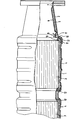
- Weitere Vorteile, Merkmale und Einzelheiten der Erfindung ergeben sich aus der nachfolgenden Beschreibung eines Ausführungsbeispiels, der eine teilweise geschnittene Seitenansicht eines Endabschnittes einer erfindungsgemäßen katalytischen Abgasentgiftungsvorrichtung zeigt.
- In dem im wesentlichen zylindrischen Außengehäuse 1,an welches konisch sich verjüngende Abgaszu- und abführstutzen 2 sich anschließen, von denen in-der Teilzeichnung nur einer zu erkennen ist, sind monolitische, wabenartig strukturierte Keramikkörpr 3 gehaltert, deren Oberfläche mit einer katalytisch wirksamen Oberflächenbeschichtung versehen ist. Zur Halterung dieser Keramikkörper sind sogenannte Blähmatten 4 vorgesehen, d.h. mit steigernder Temperatur expandierende feuerfeste Fasermatten, die für eine zentrierte Halterung im Außengehäuse auch unter Berücksichtigung der stark unterschiedlichen Ausdehnung im Betrieb der Abgasentgifiungsvorrichtung sorgen.
- Um für das Außengehäuse 1 und die anschließend Abgaszu-und abführstutzen 2, billigere, einfache Stahlbleche verwenden zu können, ist zunächst vorgesehen, daß die Innenflächen der Abgaszu- und abführstutzen 2 mit thermisch isolierenden Matten 5 überdeckt sind, die ihrerseits von einem hochtemperaturfesten Abschirmblech 6 überdeckt kwden. Dieses Abschirmblech ist an der Außenseite mit seinem am Stutzen'2 anliegenden Außenflansch 7 unmittelbar mit dem Stutzen 2 verschweißt, während der innere Rand 8 mit einem Schiebesitz klemmend unter den nach außen weisenden Ringflansch 9 eines im wesentlichen Z-förmigen gebogenen Dichtrings 10 greift, dessen Außenflansch 11 dichtend am Außengehäuse 1 anliegt, ggf. mit diesem verschweißt ist. Durch diesen Schiebesitz, der durch den Doppelpfeil angedeutet ist, kann sich das Abschirmblech 6 in axialer Richtung bei seinen erheblichen thermischen Längenänderungen bewegen. Die Temperaturen am Abschirmblech 6 liegen ja wesentlich höher als am Metallstutzen 2, der durch die Isoliermatte 5, die beispielsweise auf einer Aluminium-Silikat-Basis aufgebaut sein kann, thermisch isoliert ist.
- Zur weiteren, sowohl thermisch als auch korrosionshindernden Isolierung des Gehäuses 1 ist zusätzlich vorgesehen, daß die über die Stirnkanten nach innen gebogenen Ränder 12 der Blähmatten 4 jeweils von einem umgelegten Dichtstreifen 13 aus Metallfolie, Keramikfaserband oder verwebter Keramikmatte oder Glasfasermatte eingefaßt sind, dessen umgebogene Ränder zwischen dem Keramikkörper 3 und dem Außengehäuse verklemmt sind. Durch diese Dichtstreifen wird jeliches Durchtreten von Abgas zwischen dem Keramikkörper 3 und dem Außengehäuse verhindert, womit außer der genannten Isolierung,auch ein Ausblasen des bei hohen Temperaturen seine Reißfestigkeit weitestgeherd verlierenden Materials der Blähmatte verhindert wird.
Claims (5)
Priority Applications (1)
| Application Number | Priority Date | Filing Date | Title |
|---|---|---|---|
| AT85110292T ATE34429T1 (de) | 1984-09-01 | 1985-08-17 | Katalytische abgasentgiftungseinrichtung. |
Applications Claiming Priority (2)
| Application Number | Priority Date | Filing Date | Title |
|---|---|---|---|
| DE19843432283 DE3432283A1 (de) | 1984-09-01 | 1984-09-01 | Katalytische abgasentgiftungseinrichtung |
| DE3432283 | 1984-09-01 |
Publications (2)
| Publication Number | Publication Date |
|---|---|
| EP0176722A1 true EP0176722A1 (de) | 1986-04-09 |
| EP0176722B1 EP0176722B1 (de) | 1988-05-18 |
Family
ID=6244495
Family Applications (1)
| Application Number | Title | Priority Date | Filing Date |
|---|---|---|---|
| EP85110292A Expired EP0176722B1 (de) | 1984-09-01 | 1985-08-17 | Katalytische Abgasentgiftungseinrichtung |
Country Status (3)
| Country | Link |
|---|---|
| EP (1) | EP0176722B1 (de) |
| AT (1) | ATE34429T1 (de) |
| DE (1) | DE3432283A1 (de) |
Cited By (11)
| Publication number | Priority date | Publication date | Assignee | Title |
|---|---|---|---|---|
| FR2609308A1 (fr) * | 1987-01-02 | 1988-07-08 | Eberspaecher J | Dispositif pour l'epuration catalytique des gaz d'echappement de moteurs de vehicules |
| EP0193072B1 (de) * | 1985-02-22 | 1989-04-12 | Leistritz Aktiengesellschaft | Katalytische Abgasentgiftungseinrichtung |
| DE3834779A1 (de) * | 1988-10-12 | 1990-04-19 | Roth Technik Gmbh | Bauteilsatz fuer einen katalysator |
| EP0363681A3 (de) * | 1988-10-12 | 1991-07-03 | ROTH-TECHNIK GMBH & Co. Forschung für Automobil- und Umwelttechnik | Katalysator |
| EP1607596A1 (de) * | 2004-06-14 | 2005-12-21 | Nissan Motor Company, Limited | Katalytische Konverter und dessen Herstellung |
| WO2007059850A1 (de) * | 2005-11-25 | 2007-05-31 | Emcon Technologies Germany (Augsburg) Gmbh | Doppelwandiger trichter für eine auspuffanlage |
| WO2010123251A3 (ko) * | 2009-04-21 | 2011-01-27 | ㈜엘지하우시스 | 다공성 세라믹 구조체 및 이를 포함하는 제습/가습 장치 |
| EP2378091A1 (de) * | 2010-04-15 | 2011-10-19 | J. Eberspächer GmbH & Co. KG | Abgasbehandlungseinrichtung |
| US8763375B2 (en) | 2010-08-19 | 2014-07-01 | J. Eberspaecher Gmbh & Co. Kg | Exhaust gas cleaning device, exhaust system, removal method |
| US9222392B2 (en) | 2010-04-15 | 2015-12-29 | Eberspaecher Exhaust Technology Gmbh & Co. Kg | Exhaust gas treatment device |
| CN107084020A (zh) * | 2016-02-16 | 2017-08-22 | 本田技研工业株式会社 | 内燃机的废气净化装置 |
Families Citing this family (21)
| Publication number | Priority date | Publication date | Assignee | Title |
|---|---|---|---|---|
| DE3626728A1 (de) * | 1986-08-07 | 1988-02-18 | Leistritz Ag | Abgasreinigungsvorrichtung fuer kraftfahrzeuge |
| DE3638049A1 (de) * | 1986-11-07 | 1988-05-19 | Leistritz Ag | Abgasreinigungsvorrichtung |
| DE3626729A1 (de) * | 1986-08-07 | 1988-02-18 | Leistritz Ag | Abgasreinigungsvorrichtung fuer kraftfahrzeuge |
| DE8712267U1 (de) * | 1987-09-10 | 1987-10-22 | Süddeutsche Kühlerfabrik Julius Fr. Behr GmbH & Co KG, 7000 Stuttgart | Trägerkörper für die Herstellung eines katalytischen Reaktors zur Abgasreinigung |
| DE3820981A1 (de) * | 1988-06-22 | 1989-12-28 | Leistritz Ag | Abgasreinigungsvorrichtung mit dicht umhuellter lager- und isolationsmatte |
| DE3827863A1 (de) * | 1988-08-17 | 1990-02-22 | Leistritz Ag | Katalytische abgasreinigungsvorrichtung |
| DE3834403A1 (de) * | 1988-10-10 | 1990-04-12 | Zeuna Staerker Kg | Vorrichtung zur katalytischen reinigung von abgasen aus verbrennungsmotoren |
| DE3927895C1 (de) * | 1989-08-24 | 1990-09-13 | Leistritz Ag, 8500 Nuernberg, De | |
| DE4009945C2 (de) * | 1990-03-28 | 1996-11-14 | Gillet Heinrich Gmbh | Abgaskonverter für Brennkraftmaschinen |
| DE4100935A1 (de) * | 1991-01-15 | 1992-07-16 | Bayerische Motoren Werke Ag | Doppelwandiges abgasrohr mit zwischenliegender isolationsschicht, insbesondere katalysatorgehaeuse |
| DE4223648C2 (de) * | 1992-07-17 | 1996-02-01 | Zeuna Staerker Kg | Katalytische Abgasreinigungsvorrichtung |
| JP3479074B2 (ja) * | 1993-01-07 | 2003-12-15 | ミネソタ マイニング アンド マニュファクチャリング カンパニー | 可撓性不織マット |
| US6245301B1 (en) | 1993-08-20 | 2001-06-12 | 3M Innovative Properties Company | Catalytic converter and diesel particulate filter |
| US6726884B1 (en) | 1996-06-18 | 2004-04-27 | 3M Innovative Properties Company | Free-standing internally insulating liner |
| US5882608A (en) * | 1996-06-18 | 1999-03-16 | Minnesota Mining And Manufacturing Company | Hybrid mounting system for pollution control devices |
| DE19711789C2 (de) * | 1997-03-21 | 2000-05-25 | Zeuna Staerker Kg | Kraftfahrzeug-Abgasreinigungsvorrichtung und Verfahren zu ihrer Herstellung |
| US6923942B1 (en) | 1997-05-09 | 2005-08-02 | 3M Innovative Properties Company | Compressible preform insulating liner |
| DE10250345A1 (de) * | 2002-10-29 | 2004-05-13 | Volkswagen Ag | Brennstoffzellenanordnung |
| JP4805808B2 (ja) | 2003-01-22 | 2011-11-02 | スリーエム イノベイティブ プロパティズ カンパニー | 成形三次元絶縁体 |
| DE102004046444A1 (de) | 2004-09-24 | 2006-04-06 | Volkswagen Ag | Abgasreinigungselement |
| US7896943B2 (en) | 2008-02-07 | 2011-03-01 | Bgf Industries, Inc. | Frustum-shaped insulation for a pollution control device |
Citations (3)
| Publication number | Priority date | Publication date | Assignee | Title |
|---|---|---|---|---|
| DE2412863A1 (de) * | 1973-04-18 | 1974-10-31 | Eberspaecher J | Elastische halterung eines katalysators |
| DE2549255A1 (de) * | 1975-11-04 | 1977-05-05 | Volkswagenwerk Ag | Katalytische reinigungsanlage fuer die abgase von brennkraftmaschinen |
| FR2422028A1 (fr) * | 1978-04-08 | 1979-11-02 | Fuji Heavy Ind Ltd | Convertisseur catalytique pour l'epuration des gaz d'echappement des moteurs a combustion interne |
Family Cites Families (1)
| Publication number | Priority date | Publication date | Assignee | Title |
|---|---|---|---|---|
| DE8019813U1 (de) * | 1980-07-24 | 1980-10-23 | Paul Gillet Gmbh, 6732 Edenkoben | Keramikquellmatte, insbesondere zur Lagerung von Katalysatorblöcken in Kraftfahrzeug-Abgasanlagen |
-
1984
- 1984-09-01 DE DE19843432283 patent/DE3432283A1/de not_active Ceased
-
1985
- 1985-08-17 EP EP85110292A patent/EP0176722B1/de not_active Expired
- 1985-08-17 AT AT85110292T patent/ATE34429T1/de not_active IP Right Cessation
Patent Citations (3)
| Publication number | Priority date | Publication date | Assignee | Title |
|---|---|---|---|---|
| DE2412863A1 (de) * | 1973-04-18 | 1974-10-31 | Eberspaecher J | Elastische halterung eines katalysators |
| DE2549255A1 (de) * | 1975-11-04 | 1977-05-05 | Volkswagenwerk Ag | Katalytische reinigungsanlage fuer die abgase von brennkraftmaschinen |
| FR2422028A1 (fr) * | 1978-04-08 | 1979-11-02 | Fuji Heavy Ind Ltd | Convertisseur catalytique pour l'epuration des gaz d'echappement des moteurs a combustion interne |
Non-Patent Citations (1)
| Title |
|---|
| PATENT ABSTRACTS OF JAPAN, Band 3, Nr. 12, 31. Januar 1979, Seite 91 M 47; & JP - A - 53 137 327 (TOYOTA JIDOSHA KOGYO K.K.) 30.11.1978 * |
Cited By (16)
| Publication number | Priority date | Publication date | Assignee | Title |
|---|---|---|---|---|
| EP0193072B1 (de) * | 1985-02-22 | 1989-04-12 | Leistritz Aktiengesellschaft | Katalytische Abgasentgiftungseinrichtung |
| FR2609308A1 (fr) * | 1987-01-02 | 1988-07-08 | Eberspaecher J | Dispositif pour l'epuration catalytique des gaz d'echappement de moteurs de vehicules |
| EP0275565A1 (de) * | 1987-01-02 | 1988-07-27 | Firma J. Eberspächer | Vorrichtung für die katalytische Reinigung von Fahrzeug-Abgasen |
| DE3834779A1 (de) * | 1988-10-12 | 1990-04-19 | Roth Technik Gmbh | Bauteilsatz fuer einen katalysator |
| EP0363681A3 (de) * | 1988-10-12 | 1991-07-03 | ROTH-TECHNIK GMBH & Co. Forschung für Automobil- und Umwelttechnik | Katalysator |
| EP1607596A1 (de) * | 2004-06-14 | 2005-12-21 | Nissan Motor Company, Limited | Katalytische Konverter und dessen Herstellung |
| WO2007059850A1 (de) * | 2005-11-25 | 2007-05-31 | Emcon Technologies Germany (Augsburg) Gmbh | Doppelwandiger trichter für eine auspuffanlage |
| CN102405377B (zh) * | 2009-04-21 | 2014-05-28 | 乐金华奥斯有限公司 | 多孔性陶瓷结构体及包括该陶瓷结构体的除湿/加湿装置 |
| CN102405377A (zh) * | 2009-04-21 | 2012-04-04 | 乐金华奥斯有限公司 | 多孔性陶瓷结构体及包括该陶瓷结构体的除湿/加湿装置 |
| US8657265B2 (en) | 2009-04-21 | 2014-02-25 | Lg Hausys, Ltd. | Porous ceramic structure, and dehumidification/humidification apparatus comprising same |
| WO2010123251A3 (ko) * | 2009-04-21 | 2011-01-27 | ㈜엘지하우시스 | 다공성 세라믹 구조체 및 이를 포함하는 제습/가습 장치 |
| EP2378091A1 (de) * | 2010-04-15 | 2011-10-19 | J. Eberspächer GmbH & Co. KG | Abgasbehandlungseinrichtung |
| US20110256032A1 (en) * | 2010-04-15 | 2011-10-20 | J. Eberspaecher Gmbh & Co. Kg | Exhaust Gas Treatment Device |
| US9222392B2 (en) | 2010-04-15 | 2015-12-29 | Eberspaecher Exhaust Technology Gmbh & Co. Kg | Exhaust gas treatment device |
| US8763375B2 (en) | 2010-08-19 | 2014-07-01 | J. Eberspaecher Gmbh & Co. Kg | Exhaust gas cleaning device, exhaust system, removal method |
| CN107084020A (zh) * | 2016-02-16 | 2017-08-22 | 本田技研工业株式会社 | 内燃机的废气净化装置 |
Also Published As
| Publication number | Publication date |
|---|---|
| DE3432283A1 (de) | 1986-03-13 |
| ATE34429T1 (de) | 1988-06-15 |
| EP0176722B1 (de) | 1988-05-18 |
Similar Documents
| Publication | Publication Date | Title |
|---|---|---|
| EP0176722B1 (de) | Katalytische Abgasentgiftungseinrichtung | |
| DE2823549C3 (de) | Vorrichtung zur katalytischen Gasbehandlung | |
| DE2712207C3 (de) | Wärmetauscher mit zylindrischem Mantel und darin eingesetztem, druckraumteilendem Trennblech | |
| EP0428037A1 (de) | Filter zum Abscheiden von Verunreinigungen | |
| DE3514150C1 (de) | Katalytische Abgasentgiftungsvorrichtung mit stabilisierter Federmatte | |
| EP0193072B1 (de) | Katalytische Abgasentgiftungseinrichtung | |
| DE2751808B2 (de) | Ofendecke für einen Kohleanodenbrennofen | |
| DE2412863A1 (de) | Elastische halterung eines katalysators | |
| DE3509790C2 (de) | ||
| EP0219636B1 (de) | Abgasreinigungsvorrichtung für Kraftfahrzeuge | |
| EP0534105A2 (de) | Industriebrenner mit rekuperativer Luftvorwärmung, insbesondere zur Beheizung von Ofenräumen von Industrieöfen | |
| DE2313166A1 (de) | Katalysator-monolith zur abgasreinigung, vorzugsweise in kraftfahrzeugen | |
| DE2134749C3 (de) | Brenner | |
| DE3820981C2 (de) | ||
| DE19616341B4 (de) | Gassensor | |
| DE10202005B4 (de) | Filtereinrichtung | |
| DE3506219C2 (de) | ||
| EP0356907A2 (de) | Trägerkörper für einen katalytischen Reaktor zur Abgasreinigung | |
| DE3830352C1 (en) | Exhaust emission control device for motor vehicles | |
| DE8425922U1 (de) | Katalytische Abgasentgiftungseinrichtung | |
| DE3430400C2 (de) | Katalytische Abgasreinigungseinrichtung | |
| DE2458994A1 (de) | Anordnung zur katalytischen reinigung von abgasen | |
| DE3626729C2 (de) | ||
| DE3139957C2 (de) | Metall-Keramik-Verbindung und deren Verwendung | |
| DE2123697A1 (en) | Glass tube heat exchanger - with spring loaded seal between tube and plate |
Legal Events
| Date | Code | Title | Description |
|---|---|---|---|
| PUAI | Public reference made under article 153(3) epc to a published international application that has entered the european phase |
Free format text: ORIGINAL CODE: 0009012 |
|
| AK | Designated contracting states |
Kind code of ref document: A1 Designated state(s): AT BE FR GB |
|
| 17P | Request for examination filed |
Effective date: 19860517 |
|
| 17Q | First examination report despatched |
Effective date: 19870114 |
|
| RAP1 | Party data changed (applicant data changed or rights of an application transferred) |
Owner name: LEISTRITZ AKTIENGESELLSCHAFT |
|
| GRAA | (expected) grant |
Free format text: ORIGINAL CODE: 0009210 |
|
| AK | Designated contracting states |
Kind code of ref document: B1 Designated state(s): AT BE FR GB |
|
| REF | Corresponds to: |
Ref document number: 34429 Country of ref document: AT Date of ref document: 19880615 Kind code of ref document: T |
|
| GBT | Gb: translation of ep patent filed (gb section 77(6)(a)/1977) | ||
| ET | Fr: translation filed | ||
| PLBE | No opposition filed within time limit |
Free format text: ORIGINAL CODE: 0009261 |
|
| STAA | Information on the status of an ep patent application or granted ep patent |
Free format text: STATUS: NO OPPOSITION FILED WITHIN TIME LIMIT |
|
| 26N | No opposition filed | ||
| PGFP | Annual fee paid to national office [announced via postgrant information from national office to epo] |
Ref country code: BE Payment date: 19900731 Year of fee payment: 6 |
|
| PGFP | Annual fee paid to national office [announced via postgrant information from national office to epo] |
Ref country code: AT Payment date: 19900813 Year of fee payment: 6 |
|
| PG25 | Lapsed in a contracting state [announced via postgrant information from national office to epo] |
Ref country code: AT Effective date: 19910817 |
|
| PG25 | Lapsed in a contracting state [announced via postgrant information from national office to epo] |
Ref country code: BE Effective date: 19910831 |
|
| PGFP | Annual fee paid to national office [announced via postgrant information from national office to epo] |
Ref country code: FR Payment date: 19910902 Year of fee payment: 7 |
|
| REG | Reference to a national code |
Ref country code: GB Ref legal event code: 746 |
|
| BERE | Be: lapsed |
Owner name: LEISTRITZ A.G. Effective date: 19910831 |
|
| PGFP | Annual fee paid to national office [announced via postgrant information from national office to epo] |
Ref country code: GB Payment date: 19920817 Year of fee payment: 8 |
|
| PG25 | Lapsed in a contracting state [announced via postgrant information from national office to epo] |
Ref country code: FR Effective date: 19930430 |
|
| REG | Reference to a national code |
Ref country code: FR Ref legal event code: ST |
|
| PG25 | Lapsed in a contracting state [announced via postgrant information from national office to epo] |
Ref country code: GB Effective date: 19930817 |
|
| GBPC | Gb: european patent ceased through non-payment of renewal fee |
Effective date: 19930817 |