EP0176743B1 - Tauchmotorpumpenaggregat - Google Patents
Tauchmotorpumpenaggregat Download PDFInfo
- Publication number
- EP0176743B1 EP0176743B1 EP85110552A EP85110552A EP0176743B1 EP 0176743 B1 EP0176743 B1 EP 0176743B1 EP 85110552 A EP85110552 A EP 85110552A EP 85110552 A EP85110552 A EP 85110552A EP 0176743 B1 EP0176743 B1 EP 0176743B1
- Authority
- EP
- European Patent Office
- Prior art keywords
- motor
- planetary gearing
- shaft
- driven pump
- pump set
- Prior art date
- Legal status (The legal status is an assumption and is not a legal conclusion. Google has not performed a legal analysis and makes no representation as to the accuracy of the status listed.)
- Expired
Links
Images


Classifications
-
- F—MECHANICAL ENGINEERING; LIGHTING; HEATING; WEAPONS; BLASTING
- F04—POSITIVE - DISPLACEMENT MACHINES FOR LIQUIDS; PUMPS FOR LIQUIDS OR ELASTIC FLUIDS
- F04D—NON-POSITIVE-DISPLACEMENT PUMPS
- F04D13/00—Pumping installations or systems
- F04D13/02—Units comprising pumps and their driving means
- F04D13/021—Units comprising pumps and their driving means containing a coupling
-
- F—MECHANICAL ENGINEERING; LIGHTING; HEATING; WEAPONS; BLASTING
- F04—POSITIVE - DISPLACEMENT MACHINES FOR LIQUIDS; PUMPS FOR LIQUIDS OR ELASTIC FLUIDS
- F04D—NON-POSITIVE-DISPLACEMENT PUMPS
- F04D13/00—Pumping installations or systems
- F04D13/02—Units comprising pumps and their driving means
- F04D13/028—Units comprising pumps and their driving means the driving means being a planetary gear
Definitions
- the invention relates to a motor pump unit according to the preamble of the main claim.
- a motor pump unit corresponding to the preamble is known from DE-OS 21 11 454. Its planetary gear acts as a transmission gear and, with its housing, also serves as a support lantern for a drive motor. To dampen vibrations, the central shaft of the transmission is provided with a vibration damper designed as an auxiliary bearing. This serves to compensate for shaft movements when starting off and during operation.
- the invention has for its object to develop a low-cost, statically determined storage of the rotating parts for a submersible pump for pumping large amounts of liquid at low head.
- This object is achieved in accordance with the characterizing part of the main claim.
- This solution has made it possible to arrange the pump shaft with only one bearing within the pump housing and to form the second pump shaft bearing through the planetary gear housing due to the bending moment-transmitting coupling between the pump shaft and the output shaft of the planetary gear. Since the planetary gears usually have a large number of bearings within their housing, the forces acting on the pump shaft can be taken over and directed to the planetary gear housing.
- the structural unit formed from the pump shaft and planetary gear thus has a fixed bearing within the pump housing and a floating bearing in the form of the planetary gear housing.
- An embodiment of the invention provides that the drive motor is connected to the drive shaft of the planetary gear with the interposition of a flexible coupling. Static undetermined storage within the entire unit is thus excluded.
- the drive motor is connected directly to the planetary gear housing and its drive shaft or is connected to the stationary ring gear and the drive shaft of the planetary gear.
- the size of the unit can be significantly reduced and z.
- the bearings used within the planetary gear and the fixed bearing of the pump shaft must be checked or designed.
- a further embodiment of the invention provides that a stop cooperating with the housing of the planetary gear and attached to the pump housing or the lantern limits the axial movement of the gear housing.
- the output shaft of the planetary gear is mounted in the area of the bearing plane of the planetary gear housing or the stationary ring gear.
- a further embodiment of the invention provides that the torque support of the planetary gear housing or the stationary ring gear is designed to be shock-absorbing.
- elastic stops such as. B. rubber buffers, spring assemblies, shock absorbers or the like. With which the planetary gear housing is secured against torque, are caused by the medium conveyed by the pump shaft impacts are reduced. The same applies to the loads that occur when the submersible pump unit starts up.
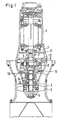
- the planetary gear 5 is arranged between a pump shaft 4 provided with the axial propeller 3 and the drive motor 1.
- the planetary gear 5, which forms a compact structural unit, consists of the drive shaft 6, which is connected to the drive motor 1 with the interposition of a flexible coupling 7.
- the housing 8 of the planetary gear 5 is rigidly or elastically secured against rotation in the lantern 9 carrying the drive motor 1, but is mounted displaceably in the axial direction.
- a rubber ring 10 arranged between the housing 8 and the lantern 9 serves to dampen vibrations and to seal an oil reservoir, which may be used, for cooling and lubrication purposes.
- the output shaft 11 of the planetary gear 5 is in the middle of a bending moment-transmitting shrink connection 12 with the Pump worlds 4 connected.
- the pump shaft 4 is fastened within the pump housing 2 in the radial bearing 13 and angular contact ball bearing 14 forming the fixed bearing. Due to the bending moment transmitting clutch 12 and the bearing within the planetary gear 5, the housing 8 of the planetary gear acts as a second pump shaft bearing, i. H. Floating bearing.
- the submersible motor pump shown in FIG. 2 corresponds essentially to FIG. 1, only here the planetary gear 5 is open in the direction of the axial propeller.
- the output shaft 11 forming the planet carrier is mounted here in the region of the bearing plane of the planetary gear. Additional moments in the transmission are thus negligibly kept to a minimum.
- a seal attached between the output shaft 11 and the pump housing 2 makes it possible to fill the entire space 16 with oil. This measure can be used in those cases in which very large powers have to be transmitted from the planetary gear 5 and the oil quantity located within a closed planetary gear would therefore not be sufficient for cooling and lubrication. In addition to the reduction of the partial scope, this also means a reduced manufacturing effort.
- FIG. 3 shows a particularly compact submersible pump unit in which a drive motor 17 which is directly coupled to the planetary gear 5 is used.
- the weight of the drive motor in this case rests on the housing 8 of the planetary gear and it is a question of calculation to what extent the bearings used here are sufficient or have to be dimensioned differently.
- the supply and discharge of the high-energy hydraulic fluid takes place via the lines 18. Rubber blocks 19 serve to support the torque.
Landscapes
- Engineering & Computer Science (AREA)
- Mechanical Engineering (AREA)
- General Engineering & Computer Science (AREA)
- Structures Of Non-Positive Displacement Pumps (AREA)
- Electromagnetic Pumps, Or The Like (AREA)
- Lubrication Of Internal Combustion Engines (AREA)
- Control Of Electric Motors In General (AREA)
- Steering Control In Accordance With Driving Conditions (AREA)
Priority Applications (1)
| Application Number | Priority Date | Filing Date | Title |
|---|---|---|---|
| AT85110552T ATE44804T1 (de) | 1984-09-14 | 1985-08-22 | Tauchmotorpumpenaggregat. |
Applications Claiming Priority (2)
| Application Number | Priority Date | Filing Date | Title |
|---|---|---|---|
| DE19843433770 DE3433770A1 (de) | 1984-09-14 | 1984-09-14 | Tauchmotorpumpenaggregat |
| DE3433770 | 1984-09-14 |
Publications (2)
| Publication Number | Publication Date |
|---|---|
| EP0176743A1 EP0176743A1 (de) | 1986-04-09 |
| EP0176743B1 true EP0176743B1 (de) | 1989-07-19 |
Family
ID=6245397
Family Applications (1)
| Application Number | Title | Priority Date | Filing Date |
|---|---|---|---|
| EP85110552A Expired EP0176743B1 (de) | 1984-09-14 | 1985-08-22 | Tauchmotorpumpenaggregat |
Country Status (5)
| Country | Link |
|---|---|
| EP (1) | EP0176743B1 (da) |
| JP (1) | JPS6172895A (da) |
| AT (1) | ATE44804T1 (da) |
| DE (2) | DE3433770A1 (da) |
| DK (1) | DK167708B1 (da) |
Families Citing this family (5)
| Publication number | Priority date | Publication date | Assignee | Title |
|---|---|---|---|---|
| JP2513595Y2 (ja) * | 1991-02-05 | 1996-10-09 | 株式会社安川電機 | 検出器の結合装置 |
| JPH09158888A (ja) * | 1995-12-08 | 1997-06-17 | Nikkiso Co Ltd | キャンドモータポンプ |
| CN101975172B (zh) * | 2010-10-08 | 2012-10-03 | 吴声震 | 行星齿轮减速潜水贯流泵 |
| CN102032199A (zh) * | 2010-10-08 | 2011-04-27 | 吴声震 | 大扭矩行星齿轮减速潜水贯流泵 |
| CN104514730A (zh) * | 2014-12-26 | 2015-04-15 | 合肥恒大江海泵业股份有限公司 | 一种潜水电泵 |
Family Cites Families (5)
| Publication number | Priority date | Publication date | Assignee | Title |
|---|---|---|---|---|
| DE832404C (de) * | 1950-03-25 | 1952-02-25 | Pleuger K G | Durch eine Welle von ueber Tage angetriebene Tiefbrunnenpumpe |
| DE1004929B (de) * | 1953-10-30 | 1957-03-21 | Amag Hilpert Pegnitzhuette A G | Kreiselpumpe mit fliegend angeordnetem Laufrad |
| FR1150131A (fr) * | 1956-04-30 | 1958-01-08 | Const Mecaniques Chenard Et Wa | Installation pour la transmission d'un mouvement de rotation entre un organe menant et un organe mené |
| DE2111454A1 (de) * | 1971-03-10 | 1972-09-21 | Klein Schanzlin & Becker Ag | Kreiselpumpe,insbesondere vertikaler Bauart,mit fliegend angeordnetem Laufrad und einem Umlaufgetriebe |
| US4040312A (en) * | 1974-10-29 | 1977-08-09 | Eaton Corporation | Planetary reduction drive unit |
-
1984
- 1984-09-14 DE DE19843433770 patent/DE3433770A1/de not_active Withdrawn
-
1985
- 1985-08-22 EP EP85110552A patent/EP0176743B1/de not_active Expired
- 1985-08-22 DE DE8585110552T patent/DE3571676D1/de not_active Expired
- 1985-08-22 AT AT85110552T patent/ATE44804T1/de not_active IP Right Cessation
- 1985-09-06 DK DK407585A patent/DK167708B1/da not_active IP Right Cessation
- 1985-09-11 JP JP60201473A patent/JPS6172895A/ja active Pending
Also Published As
| Publication number | Publication date |
|---|---|
| DE3433770A1 (de) | 1986-03-27 |
| DK407585D0 (da) | 1985-09-06 |
| EP0176743A1 (de) | 1986-04-09 |
| DK407585A (da) | 1986-03-15 |
| JPS6172895A (ja) | 1986-04-14 |
| ATE44804T1 (de) | 1989-08-15 |
| DE3571676D1 (en) | 1989-08-24 |
| DK167708B1 (da) | 1993-12-06 |
Similar Documents
| Publication | Publication Date | Title |
|---|---|---|
| DE19781320B4 (de) | Wälzlager mit Geräuschdämpfung | |
| EP0176743B1 (de) | Tauchmotorpumpenaggregat | |
| DE69118133T2 (de) | Überflutbare Arbeitsmaschine | |
| EP0474004A2 (de) | Eine Anlaufhilfe aufweisender Synchronmotor | |
| DE69114239T2 (de) | Dichtung. | |
| DE3516903A1 (de) | Schiffsgetriebe | |
| DE69801740T3 (de) | Kreiselpumpe mit Radialdichtung | |
| EP0188713B1 (de) | Ölfördereinrichtung für Vakuumpumpen | |
| DE29522268U1 (de) | Querantrieb | |
| DE19616578C1 (de) | Antriebskopf für ein drehantreibbares Gestänge, insbesondere zum Antreiben einer Bohrlochpumpe | |
| EP1035329A2 (de) | Strömungsmaschinenrad und Verwendung desselben | |
| DE202010002882U1 (de) | Pumpenantrieb eines Automatgetriebes umfassend einen hydrodynamischen Drehmomentwandler, bei dem die Ölpumpe nicht koaxial zum Drehmomentwandler angeordnet ist | |
| WO2009043619A1 (de) | Pumpe, insbesondere für ein hydraulikaggregat einer elektronisch regelbaren fahrzeugbremsanlage | |
| DE2256361A1 (de) | Pumpenaggregat | |
| DE1971856U (de) | Getriebemotor mit schmieroelpumpe. | |
| DE2409856A1 (de) | Elektromechanischer antrieb, insbesondere stellantrieb, getriebemotor oder dergleichen | |
| DE3125119A1 (de) | Geraeuschgedaempftes hydrostatgetriebe | |
| DE873421C (de) | Getriebemotor, insbesondere Innenlaeufer-Getriebemotor | |
| AT116305B (de) | Kegelradgetriebe. | |
| DE1722508U (de) | Umlaufschmierung. | |
| DE19842031C2 (de) | Vorrichtung zum Abdichten einer sich drehenden Welle beim Durchgang durch eine Trennwand zwischen flüssigen und gasförmigen Medien, im besonderen als Stevenrohr-Abdichtung an Wasserfahrzeugen | |
| AT210223B (de) | Hydrostatische Kupplung | |
| DE8805310U1 (de) | Hydraulikpumpe | |
| DE1915735C3 (de) | Hydraulische Axialkolbenmaschine der Schwenkscheiben-Bauart | |
| DE2111454A1 (de) | Kreiselpumpe,insbesondere vertikaler Bauart,mit fliegend angeordnetem Laufrad und einem Umlaufgetriebe |
Legal Events
| Date | Code | Title | Description |
|---|---|---|---|
| PUAI | Public reference made under article 153(3) epc to a published international application that has entered the european phase |
Free format text: ORIGINAL CODE: 0009012 |
|
| AK | Designated contracting states |
Kind code of ref document: A1 Designated state(s): AT BE CH DE FR GB IT LI LU NL SE |
|
| 17P | Request for examination filed |
Effective date: 19861009 |
|
| 17Q | First examination report despatched |
Effective date: 19870626 |
|
| RAP1 | Party data changed (applicant data changed or rights of an application transferred) |
Owner name: KSB AKTIENGESELLSCHAFT |
|
| GRAA | (expected) grant |
Free format text: ORIGINAL CODE: 0009210 |
|
| AK | Designated contracting states |
Kind code of ref document: B1 Designated state(s): AT BE CH DE FR GB IT LI LU NL SE |
|
| PG25 | Lapsed in a contracting state [announced via postgrant information from national office to epo] |
Ref country code: NL Effective date: 19890719 Ref country code: BE Effective date: 19890719 |
|
| REF | Corresponds to: |
Ref document number: 44804 Country of ref document: AT Date of ref document: 19890815 Kind code of ref document: T |
|
| PG25 | Lapsed in a contracting state [announced via postgrant information from national office to epo] |
Ref country code: AT Effective date: 19890822 |
|
| REF | Corresponds to: |
Ref document number: 3571676 Country of ref document: DE Date of ref document: 19890824 |
|
| PG25 | Lapsed in a contracting state [announced via postgrant information from national office to epo] |
Ref country code: LU Free format text: LAPSE BECAUSE OF NON-PAYMENT OF DUE FEES Effective date: 19890831 Ref country code: LI Effective date: 19890831 Ref country code: CH Effective date: 19890831 |
|
| ITF | It: translation for a ep patent filed | ||
| GBT | Gb: translation of ep patent filed (gb section 77(6)(a)/1977) | ||
| ET | Fr: translation filed | ||
| NLV1 | Nl: lapsed or annulled due to failure to fulfill the requirements of art. 29p and 29m of the patents act | ||
| REG | Reference to a national code |
Ref country code: CH Ref legal event code: PL |
|
| PLBE | No opposition filed within time limit |
Free format text: ORIGINAL CODE: 0009261 |
|
| STAA | Information on the status of an ep patent application or granted ep patent |
Free format text: STATUS: NO OPPOSITION FILED WITHIN TIME LIMIT |
|
| 26N | No opposition filed | ||
| ITTA | It: last paid annual fee | ||
| EAL | Se: european patent in force in sweden |
Ref document number: 85110552.8 |
|
| REG | Reference to a national code |
Ref country code: GB Ref legal event code: IF02 |
|
| PGFP | Annual fee paid to national office [announced via postgrant information from national office to epo] |
Ref country code: GB Payment date: 20040726 Year of fee payment: 20 |
|
| PGFP | Annual fee paid to national office [announced via postgrant information from national office to epo] |
Ref country code: DE Payment date: 20040727 Year of fee payment: 20 |
|
| PGFP | Annual fee paid to national office [announced via postgrant information from national office to epo] |
Ref country code: FR Payment date: 20040820 Year of fee payment: 20 |
|
| PGFP | Annual fee paid to national office [announced via postgrant information from national office to epo] |
Ref country code: SE Payment date: 20040823 Year of fee payment: 20 |
|
| PG25 | Lapsed in a contracting state [announced via postgrant information from national office to epo] |
Ref country code: GB Free format text: LAPSE BECAUSE OF EXPIRATION OF PROTECTION Effective date: 20050821 |
|
| REG | Reference to a national code |
Ref country code: GB Ref legal event code: PE20 |
|
| EUG | Se: european patent has lapsed |