EP0177197B1 - Tendon pour plate-forme flottante à jambe de traction et méthode électrique de protection contre la corrosion de celui-ci - Google Patents
Tendon pour plate-forme flottante à jambe de traction et méthode électrique de protection contre la corrosion de celui-ci Download PDFInfo
- Publication number
- EP0177197B1 EP0177197B1 EP85306356A EP85306356A EP0177197B1 EP 0177197 B1 EP0177197 B1 EP 0177197B1 EP 85306356 A EP85306356 A EP 85306356A EP 85306356 A EP85306356 A EP 85306356A EP 0177197 B1 EP0177197 B1 EP 0177197B1
- Authority
- EP
- European Patent Office
- Prior art keywords
- tendon
- coating
- corrosion
- straight steel
- anode
- Prior art date
- Legal status (The legal status is an assumption and is not a legal conclusion. Google has not performed a legal analysis and makes no representation as to the accuracy of the status listed.)
- Expired
Links
Images


Classifications
-
- C—CHEMISTRY; METALLURGY
- C23—COATING METALLIC MATERIAL; COATING MATERIAL WITH METALLIC MATERIAL; CHEMICAL SURFACE TREATMENT; DIFFUSION TREATMENT OF METALLIC MATERIAL; COATING BY VACUUM EVAPORATION, BY SPUTTERING, BY ION IMPLANTATION OR BY CHEMICAL VAPOUR DEPOSITION, IN GENERAL; INHIBITING CORROSION OF METALLIC MATERIAL OR INCRUSTATION IN GENERAL
- C23F—NON-MECHANICAL REMOVAL OF METALLIC MATERIAL FROM SURFACE; INHIBITING CORROSION OF METALLIC MATERIAL OR INCRUSTATION IN GENERAL; MULTI-STEP PROCESSES FOR SURFACE TREATMENT OF METALLIC MATERIAL INVOLVING AT LEAST ONE PROCESS PROVIDED FOR IN CLASS C23 AND AT LEAST ONE PROCESS COVERED BY SUBCLASS C21D OR C22F OR CLASS C25
- C23F13/00—Inhibiting corrosion of metals by anodic or cathodic protection
- C23F13/02—Inhibiting corrosion of metals by anodic or cathodic protection cathodic; Selection of conditions, parameters or procedures for cathodic protection, e.g. of electrical conditions
Definitions
- the present invention relates to a tendon of a tension leg platform (hereinafter referred to as the TLP) for producing offshore petroleum and gas.
- the present invention also relates to a method for electrical corrosion-protection for the tendon of the TLP.
- Tendons are members used for anchoring the platform of a TLP to the sea bottom and are made of the coupled steel pipes.
- the problems to be solved at present are how to provide a structure which can be installed offshore at a water depth of 400 - 1000 m as a conventional scaffolding type-offshore structure is considered to be unable to meet the requirements for an offshore structure installed at such a water depth.
- Various offshore structures said to exceed the limitations of the conventional scaffolding type, have been proposed.
- the TLP is considered to be one of the most promising of the structures which meet the requirements mentioned above and, hence, practical utilization thereof has begun.
- steel pipes have not been used heretofore for anchoring a platform or the like to the sea bottom in deep areas.
- the steel material used for tendons must have a high mechanical durability. Another problem is how to protect the tendons from corrosion for a target life of from 20 to 30 years.
- the Japanese technical journal « Piping and Plant (March, 1981) illustrates one example of corrosion-protection of an offshore structure (c. f. page 34, right column, lines 6-9 and Table 4). That is, the parts of tendons immersed in seawater are galvanically corrosion-protected, and the upper parts of tendons above the ebb and flow level have a thin coating applied on a zinc-rich paint undercoat. When this corrosion-protection method is applied for tendons which are immersed in seawater, the tendons are galvanically corrosion-protected over their entire length and surface. Such an application will now be considered in more detail.
- a tendon is manufactured by connecting steel pipes.
- a galvanic current-anode (sacrificing anode) system in which the power sources are dispersed, is more advisable than an external power-system using a centralized power source.
- the tendons are corrosion-protected for service over 30 years in a southern area of the northern Sea by using aluminum anodes, each of which is attached to a steel pipe 500 mm in diameter and 12 m in length, the net weight of each aluminum anode is presumably 340 kg.
- a coating can be formed in the factory on a major portion of a tendon, the screws used for coupling the steel pipes remain uncoated, and further, if the coating is preliminarily applied on the screws, it may be damaged by a fastening jig, e. g., a tongue for fastening the couplings to the steel pipes. Still another problem is that such a coating is generally considered to be less durable than the galvanic corrosion-protection. A further problem is that the coating, which may be selectively applied on the straight section of a tendon or be extended to the coupling parts of a tendon, has a low durability at the edges thereof.
- the corrosion- . protection of tendons should fulfill the following requirements.
- the tendons are subjected to great tension in sea water, since the TLP is in a state of continual movement due to wave action, and thus fatigue corrosion of the tendons is likely to occur.
- the galvanic corrosion-protecting method is effective for drastically lessening fatigue corrosion, as described in OTC paper No. 4449 (May, 1983) (c. f. Fig. 7).
- the galvanic corrosion-protection therefore can be advantageously used for protecting tendons, irrespective of whether it is used alone or in combination with the coating method.
- the core metal of the anode is fillet welded to the steel pipe to be protected. If this fillet welding is readily applied for the corrosion protection of tendons, not only would serious fatigue corrosion occur, but also the galvanic current anodes per se would fall off of the tendons during the service. Accordingly, when the galvanic current-anode system is applied for corrosion-protecting tendons, the galvanic current-anodes must be attached to the tendons in such a manner that the fatigue corrosion characteristic of the tendons are not seriously influenced and further, that the galvanic current-anodes do not fall off after a long period of time. Unless such attachment is accomplished, the intended corrosion-protection can not be attained, but instead, fatigue corrosion would be caused by the attachment of the galvanic current-anodes.
- a complex, galvanized and coating-corrosion protection is applied to the tendons, whereby the tendons are provided with an insulative corrosion protection coating having a good damage resistance on the straight section thereof, and a sprayed aluminium layer is applied on the outer surface thereof.
- the welding point of a galvanic current-anode is offset from the line of stress applied to the tendon and, further, butt welded steel materials are used at the welding point.
- a tendon of a TLP wherein the tendon comprises
- an electrical protection method for a tendon of a TLP wherein the tendon comprises straight steel pipes, each having screw couplings at the ends thereof, each screw coupling having convex and concave parts on the circumeferential part thereof, for fastening the screw coupling, characterized in that at least one of said screw couplings at the ends of each straight steel pipe is provided with a projection in a rod form, which protrudes from the convex parts of the screw couplings and which consists of the same material as that of the screw couplings and, further, a galvanic current-anode, which is wound around and attached to the straight steel pipes or the screw couplings, has a core metal part made of steel and is butt-welded to each projection in the form of a rod.
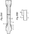
- the tendon according to the present invention comprises a straight steel pipe 1 and screw couplings 2.
- the screw couplings 2 have a spline 3 for fastening the section 2 to a neighbouring straight steel pipe (not shown).
- the concave and convex parts of the spline 3 are arranged circumferentially and virtually equi-distant from each other on the body of couplings.
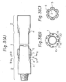
- the convex parts of the spline 3 have a plurality of projections 4 in the form of a rod, which are extended from a part of each convex part of the spline 3 and which are arranged circumferentially and virtually equi-distant from each other.
- the straight steel pipe 1 is provided with a galvanic current-anode 5, which is made of an appropriate anode metal, and is wound around in the form of a ring (so-called bracelet form) and attached to the straight steel pipe 1.
- a galvanic current-anode 5 which is made of an appropriate anode metal, and is wound around in the form of a ring (so-called bracelet form) and attached to the straight steel pipe 1.
- metallic core members 7 are rigidly secured to the galvanic current anode 5 and are welded to the ends of the projections 4 through the weld zone 6.
- the weld zone 6 is located at a position such that it is not influenced by the stress acting lines 10 (Fig. 2 (A)), and thus, there is no dangerthat the weld zone 6 will act as a notch and cause the destruction of the tendon.
- the attachment of the galvanic current-anode 5 to the straight steel pipe 1 is in no way limited to the embodiment as shown in Fig. 1 (A) but may be any way, in which the attached zone will not act as a notch and cause the destruction of the tendon.
- the straight steel pipe 1 comprises, on its outer surface, a coating 8 having a good damage resistance and being insulative.
- the screw couplings 2 have, on the outer surface thereof, the sprayed aluminum layer 9.
- the ends of the coating 8 are in contact with the ends of the sprayed aluminum layer 9.
- the former and latter ends may butt against one another or may overlap one another. According to the embodiment of the tendon shown in Figs.
- one unit of the pipe and coupling-assembly has a male screw 12 at one end and a female screw 13 at the other end.
- units of the pipe and coupling-assembly having female screws. at both ends, and other units having male screws at both ends are alternately connected with each other.
- the coating 8 according to the present invention is further described.
- the « insulative • property of coating 8 is that of an electric insulator.
- the « good damage resistance of coating 8 is that it has sufficient strength and flexibility so as to resist impact and sway exerted on the straight steel pipe 1 prior to, during, and subsequent to, installation or assembly.
- the coating 8 should have a corrosion protection with a life-expectancy of 20 years or longer or 30 years or longer.
- the coating 8 may be a 0.2 mm or more thick layer of an insulative epoxy resin. This coating is appropriate for corrosion protection with a life-expectancy of 30 years.
- the coating 8 may also be a 1 mm or more- thick layer of an insulative polyethylene resin-..
- the layer thickness should be adjusted to 2 mm or more for the polyethylene resin coating, and the epoxy resin layer should be provided with a protective layer which can consist of polyurethane, polyester reinforced with glass, polymer cement or mortar, or resin mortar.
- the polymer cement or mortar consists mainly of cement or mortar and contains a small amount of anti-crazing agent, such as acrylic polymer or SB rubber.
- the resin mortar consists of paint, and usually the paint is mainly composed of organic synthetic resin, e. g., epoxy resin, into which a large amount of sand (SiO2) is added.
- the resin mortar is free of cement.
- the protective layer has usually a thickness of 2 mm or more.
- the coating 8 is preferably a laminate of a thin epoxy layer and a thick polyurethane layer or a thick layer of polyethylene having a thicknes of 2 mm or more in the light of the respective characteristics of the coating 8.
- the thin epoxy layer can be applied on the straight steel pipe by means of various methods, such as spraying, continuous-flow curtain coating, and electrostatic coating.
- the paint used for thin epoxy layer may be a solvent-based coating, two-pack type coating or powder coating.
- the thick polyurethane coating may be formed by means of spraying, continuous-flow curtain coating, or by molding the two-pack urethane.
- the thick polyethylene coating can be applied on the straight steel pipe 1 by means of fluidization dip coating of the powder coating, or dispersing or melt-extruding the powder coating.
- a heat-shrinkable sheet or tube may be used by heating and shrinking the sheet or tube and then applying it to the straight steel pipe 1.
- the thickness of the coating 8 should not exceed 5 mm, in the light of economics and its characteristics.
- the steel material may be chemical-conversion treated or a primer applied thereto by any appropriate method, prior to the coating.
- the sprayed aluminum layer 9 protects the outer surface of the screw couplings 2 against the formation of rust, prior to installing the tendons, and also protects the ends of coating 8 comprised of resin material during the life of the tendons.
- An appropriate thickness of the sprayed aluminum layer 9 is from approximately 100 to 300 ⁇ m.
- the sprayed aluminum layer 9 can be formed on the screw couplings 2 by means of a flame spraying or arc method. The so formed sprayed aluminum layer 9 may be further subjected to sealing of the pores, if necessary.
- the sprayed aluminum layer 9 is sufficiently rigid that it will not be damaged by a fastening jig (tongue) which is engaged with the convex and concave parts of the screw coupling 2 for turning and securing the same to a steel pipe.
- the galvanic current-anode 5 suppresses the dissolution of the sprayed aluminum layer 9 to the minimum, thereby maintaining the shielding effect of the sprayed aluminum layer 9. If any damage of the sprayer aluminum layer 9 and the coating 8 occurs, and hence the steel material of the screw coupling 2 is exposed, the galvanic current-anode 5 electrically protects the exposed surfaces against corrosion.
- Aluminum alloy which is usually used for the galvanic current-anodes, is appropriate material for the galvanic current-anode 5 for the electrical corrosion protection of the tendons of a TLP.
- approximately 90 % by area of the tendon is corrosion-protected by the coating 8 applied on the straight steel pipe, and approximately 10 % by area of the tendon is corrosion-protected by the sprayed aluminum layer 9 applied on the screw coupling.
- the coating 8 will presumably be damaged over an area of approximately 5 % of the total coated area during the life of tendon, which will lead to exposure of approximately 5 % of the total coated area of the straight steel pipe 1 which is conductive.
- This conductive area and the other conductive area, i. e., the sprayed aluminum layer 9 must be protected by the galvanic current-anode 5.
- a net of 340 kg of aluminum is necessary for corrosion protection of an ordinary steel pipe for a tendon, provided that it is corrosion-protected exclusively by the galvanic current-anode.
- the galvanic current-anode 5 comprises three fan-shaped aluminum sheets 15 which are connected via the core metal members 18 and 19.
- the core metal members 18 and 19 are attached to the respective ends of each fan-shaped aluminum sheet 15 and are welded to one another via the weld zone 20.
- the so connected, fan-shaped aluminum sheets 15 are in the form of a ring or so-called bracelet, and are wound around and attached to the straight steel pipe 1.
- the galvanic current-anode 5 is connected to the projections 4 through the weld zone 6.
- the core metal members 7 extend in paraitetto the axia) force exerted on the tendon.
- the ends of the core metal members 7 and the projections 4 are butt-welded at the weld zone 6.
- the core metal members 7 have a rectangular cross section.
- the cross sectional shape of the core metal members 7 is not limited to rectangular, but preferably, the cross sectional shape of the core metal members 7 is the same as that of the projections 4.
- the weld zone 6 When the galvanic current-electrode 5 is attached, the weld zone 6 is located outside the line 10 of stress exerted on the tendon, and, therefore, the weld zone 6 does not act as a notch causing the fatigue corrosion which results in the tendon destruction.
- the tension of a TLP is not exerted to the galvanic current-electrode 5, since it is merely attached, not welded, to the straight steel pipe 1.
- the welding of the galvanic current-electrode 5 is performed with the aid of the core metal members 7 which are butt-welded to the projections 4.
- the galvanic current-electrode 5 is therefore highly resistant to destruction due to movement of the TLP caused by wave action.
- the projections 4, six of which are shown in the embodiment in Figs. 3 (A), (B), and (C), may be integral parts of the screw coupling 2 or may be parts connected to the screw coupling 2 by welding. These parts may be hardened and then tempered after the welding. Other methods may be employed for providing the projections 4, provided that the projections 4 do not act as notches with respect to the stress applied to the body of a tendon.
- the transitional region between the spline 3 and the projections 4, as well as the transitional region between the projections 4 and the weld zone 6, should not act as such a notch. From this view point, these transitional regions should evidently have a smooth contour and surface.
- projections 4 and the galvanic current-anode 5 comprises three fan-shaped, members in the embodiment shown in Figs. 3 (A), (B), and (C)
- various modifications are possible with regard to the number of projections 4 and the separation of the electrode members, such as by using a pair of fan-shaped members or using an integral single annular member.
- test pieces were manufactured by using five steel pipes having an outer diameter of 216.3 mm, thickness of 8.2 mm and length of 3 m. A circular cover was welded to each end of the steel pipes to protect the pipe interior from corrosion. The entire outer surface of the steel pipes was rough-blasted by steel grids. The so-prepared steel pipes were corrosion protected by five different methods to prepare the test pieces A through E, described below.
- test pieces A through E were exposed outdoors for six months, and their appearance was then observed.
- the test pieces A through E were subsequently entirely immersed in seawater besides a dike at the seashore. After a lapse of 2 years, the pieces were removed from the seawater and every part thereof was carefully scrutinized. The results are described as follows.
- Test Piece A (Invention)
- Both ends of a pipe including circular covers 0.2 mm thick aluminum sprayed layer formed by the arc method.
- Aluminum-alloy anode a bracelet type aluminum alloy anode 5 kg in weight was wound around the coating mentioned in item A, above, in such a manner that the ends of the coating and anode were aligned with one another. The core metal members of the anode were welded to sprayed aluminum coating.
- Test Piece B (Invention)
- An aluminum-alloy anode a bracelet type aluminum alloy anode 5 kg in weight was wound around the coating mentioned in item A, above, in such a manner that the ends of the coating and anode were aligned with one another. The core metal members of the anode were welded to the sprayed aluminum layer.
- Test Piece C (Comparative Example)
- Test Piece D (Comparative Example)
- One aluminum alloy electrode in a bracelet form, having net weight of 17 kg was wound around each of both ends of a pipe, and the core metal members were welded to the pipe body.
- Test Piece E (Comparative Example)
- test pieces approximately one third in size of the actual tendon of a TLP, were manufactured.
- the steel pipes of the test pieces were 196 mm in outer diameter, and 8.5 mm in wall thickness.
- the screw couplings were 203 mm in the largest outer diameter, and 200 mm in length.
- the total length of the test pieces was 2000 mm.
- the steel pipes were made of steel grade SM50B.
- the four convex and concave parts of the spline were formed on the screw coupling and were equispaced from each other.
- Two test pieces were provided with four projections in the form of a rod, having a rectangular cross-section, being 7 mm x 14 mm in size, and protruding from the convex parts of the spline.
- the galvanic current anode was prepared by connecting a pair of ring halves, made of an aluminum sheet (1 526 kg) 170 mm in inner diameter, 30 mm in thickness and 30 mm in width, with one another by a pair of the metal core members which were attached to the respective aluminum sheets.
- An additional four metal core members were provided for connecting the galvanic current-anode to the projections . mentioned above.
- Each two additional metal core members were fixed to the respective aluminum sheet.
- the six metal core members were made of steel.
- a pair of aluminum sheets were fitted around the steel pipe, and the metal core members for connecting the aluminum sheet were butt-welded.
- the aluminum anode, which was attached in the form of a ring around the steel pipe, was connected to a pipe by one of the following three methods.
- Test Piece A (Comparative Sample)
- the aluminum anode was rigidly secured to the outer surface of a pipe by directly fillet-welding the four metal core members to the outer surface of a pipe.
- Test Piece B (Comparative Sample)
- the aluminum anode was rigidly connected to the projections by overlapping the four metal core members of the anode and the four projections of the screw coupling over a length of 15 mm and then fillet-welding only the outer surface of the overlapped metal core members and projections.
- the aluminum anode was rigidly connected to the projections by butt-welding and the metal core members of the aluminum anode via the 60° (groove angle)-grooves of the projections and metal core members.
- the above three test pieces were subjected to the fatigue corrosion test in artificial sea water stipulated in an ASTM Standard.
- the tensile stress was applied to the three text bodies by the single swing axial tensile load method, in which the scope of stress was 200 N/mm 2 and the repetition speed was 0.5 Hz.
- the results of the fatigue corrosion test were as follows.
- the test was stopped at the repetition number of 1,925,055 times. No cracks were generated on the steel pipe. Cracks were locally generated, however, in the fillet-welds between the metal core members of aluminum electrode and the projections.
- the resistance against fatigue corrosion is improved by using the connecting method of a galvanic current-anode according to the present invention, in which it is not directly, rigidly connected to the steel pipe and the screw coupling.
- butt-welding is more appropriate for welding the galvanic current anode to the screw coupling through the metal core members of the anode and the projections of the coupling, than is fillet welding, since cracks, which can result in a . falling off of the galvanic current anode, are less liable to be generated in the butt welding than in the fillet welding.
Landscapes
- Chemical & Material Sciences (AREA)
- Engineering & Computer Science (AREA)
- Materials Engineering (AREA)
- Mechanical Engineering (AREA)
- Metallurgy (AREA)
- Organic Chemistry (AREA)
- Prevention Of Electric Corrosion (AREA)
Claims (6)
Applications Claiming Priority (4)
| Application Number | Priority Date | Filing Date | Title |
|---|---|---|---|
| JP186564/84 | 1984-09-07 | ||
| JP18656484A JPH0228514B2 (ja) | 1984-09-07 | 1984-09-07 | Taikyuseioyobifusetsuseinosuguretatenshonregupuratsutofuoomukyakukan |
| JP241950/84 | 1984-11-16 | ||
| JP59241950A JPS61119690A (ja) | 1984-11-16 | 1984-11-16 | テンシヨンレグプラツトフオ−ム脚管の電気防食方法 |
Publications (2)
| Publication Number | Publication Date |
|---|---|
| EP0177197A1 EP0177197A1 (fr) | 1986-04-09 |
| EP0177197B1 true EP0177197B1 (fr) | 1988-10-19 |
Family
ID=26503843
Family Applications (1)
| Application Number | Title | Priority Date | Filing Date |
|---|---|---|---|
| EP85306356A Expired EP0177197B1 (fr) | 1984-09-07 | 1985-09-06 | Tendon pour plate-forme flottante à jambe de traction et méthode électrique de protection contre la corrosion de celui-ci |
Country Status (3)
| Country | Link |
|---|---|
| US (1) | US4614461A (fr) |
| EP (1) | EP0177197B1 (fr) |
| DE (1) | DE3565696D1 (fr) |
Families Citing this family (13)
| Publication number | Priority date | Publication date | Assignee | Title |
|---|---|---|---|---|
| US4941775A (en) * | 1988-02-26 | 1990-07-17 | Benedict Risque L | Cathodic protection of critical offshore marine structure critical components by making the critical component noble (passive) to the balance of the platform |
| US5087154A (en) * | 1990-09-17 | 1992-02-11 | Mpt Services, Inc. | Coatings and process affording corrosion protection for marine structures |
| US5348425A (en) * | 1992-11-10 | 1994-09-20 | Heiliger Robert W | Piston cylinder device with a protective coating and method of producing such a coating |
| US5380131A (en) * | 1993-02-25 | 1995-01-10 | Mpt Services, Inc. | System for corrosion protection of marine structures |
| BR9303646A (pt) | 1993-08-31 | 1995-04-25 | Petroleo Brasileiro Sa | Sistema de fundação para plataformas de pernas atirantadas |
| US6036404A (en) | 1993-08-31 | 2000-03-14 | Petroleo Brasileiro S.A.-Petrobras | Foundation system for tension leg platforms |
| US5755533A (en) * | 1994-12-16 | 1998-05-26 | Shell Oil Company | Tendon foundation guide cone assembly and method |
| US5480521A (en) * | 1994-12-16 | 1996-01-02 | Shell Oil Company | Tendon foundation guide cone assembly and anode |
| US6554992B1 (en) * | 1995-06-07 | 2003-04-29 | Mcwane, Inc. | Aluminum alloy exterior coating for underground ductile iron pipe |
| US5786976A (en) * | 1996-07-16 | 1998-07-28 | Hydraflow | Coupling with hard metallic ductile conductive coating |
| DE102009008069B4 (de) * | 2009-02-04 | 2011-02-24 | Tkms Blohm + Voss Nordseewerke Gmbh | Vorrichtung zum Bewuchs- und Korrosionsschutz vor Seewassereintritten in Schiffen |
| GB2554087B (en) * | 2016-09-19 | 2020-01-01 | Equinor Energy As | Sacrificial anode protection of a subsea umbilical |
| CN107541732B (zh) * | 2017-10-13 | 2019-07-12 | 大连科迈尔防腐科技有限公司 | 一种海上拉伸阳极系统及其安装方法 |
Family Cites Families (12)
| Publication number | Priority date | Publication date | Assignee | Title |
|---|---|---|---|---|
| NL279640A (fr) * | 1961-10-05 | |||
| US3232857A (en) * | 1962-08-17 | 1966-02-01 | Bunker Hill Company | Cathodic protection anode structure |
| USRE27529E (en) * | 1972-08-07 | 1972-12-12 | Galvanic anode | |
| US3887449A (en) * | 1973-05-21 | 1975-06-03 | Chromalloy American Corp | Coating method and composition for the sacrificial protection of metal substrates |
| US4285615A (en) * | 1978-12-13 | 1981-08-25 | Conoco, Inc. | Corrosion resistant tension leg cables |
| GB2050427B (en) * | 1979-03-30 | 1983-02-02 | Global Cathodic Protection Ltd | Sacrificial anode for cathodic protection |
| NO800911L (no) * | 1979-03-30 | 1980-10-01 | Global Cathodic Protection Ltd | Katodisk beskyttelse. |
| US4540314A (en) * | 1982-03-25 | 1985-09-10 | Fluor Subsea Services, Inc. | Tension leg means and method of installing same for a marine platform |
| US4415293A (en) * | 1982-04-05 | 1983-11-15 | Shell Oil Company | Offshore platform free of marine growth and method of reducing platform loading and overturn |
| GB2137229A (en) * | 1983-02-23 | 1984-10-03 | Jerry Donald Hughes | Internal sacrificial anode for subsurface conduit |
| US4506485A (en) * | 1983-04-12 | 1985-03-26 | State Of California, Department Of Transportation | Process for inhibiting corrosion of metal embedded in concrete and a reinforced concrete construction |
| US4484840A (en) * | 1983-09-28 | 1984-11-27 | Shell Offshore Inc. | Method and apparatus for installing anodes on steel platforms at offshore locations |
-
1985
- 1985-09-05 US US06/772,743 patent/US4614461A/en not_active Expired - Fee Related
- 1985-09-06 DE DE8585306356T patent/DE3565696D1/de not_active Expired
- 1985-09-06 EP EP85306356A patent/EP0177197B1/fr not_active Expired
Also Published As
| Publication number | Publication date |
|---|---|
| US4614461A (en) | 1986-09-30 |
| DE3565696D1 (en) | 1988-11-24 |
| EP0177197A1 (fr) | 1986-04-09 |
Similar Documents
| Publication | Publication Date | Title |
|---|---|---|
| US4614461A (en) | Tendon of TLP and electrical corrosion protecting method of the same | |
| CA2814051A1 (fr) | Systeme indicateur d'usure pour systemes de revetement de protection contre la corrosion en mer | |
| CA2885505A1 (fr) | Point d'amarrage pour navires | |
| US4146448A (en) | Protection of a stern tube shaft liner | |
| GB2194962A (en) | Cathodic protection of metal surfaces | |
| AU604813B2 (en) | Method for constructing inspectable welded joints which are resistant to marine biofouling, and welded joints formed thereby | |
| EP0132332B1 (fr) | Système de protection cathodique de tubes | |
| JP2023043574A (ja) | 防食被覆構造および該防食被覆構造を備えた海洋構造物 | |
| JPH0228514B2 (ja) | Taikyuseioyobifusetsuseinosuguretatenshonregupuratsutofuoomukyakukan | |
| JPH06173287A (ja) | 海洋鋼構造物の防食構造 | |
| JPS5829916A (ja) | 海用鋼構造物の防食施工方法 | |
| Schmitt et al. | Corrosion performance of constructional steels in marine applications | |
| JP3823922B2 (ja) | 鋼管矢板および矢板壁 | |
| JP2000015744A (ja) | 重防食被覆を有する鋼製杭 | |
| JP2001152475A (ja) | 透明性を有する被覆防食用カバー | |
| CN201043641Y (zh) | 在海洋工程中使用的带有阴极保护装置的单层保温配重管 | |
| JPS6325074B2 (fr) | ||
| JP3128801U (ja) | 鋼製矢板の防食用保護カバー | |
| JP4068756B2 (ja) | 海洋構造物用重防食被覆鋼矢板 | |
| JP2960637B2 (ja) | 鋼管杭の防食構造体 | |
| JP2000303188A (ja) | 海洋構造物用重防食被覆鋼材 | |
| CN212716034U (zh) | 一种牺牲阳极和玻纤套筒协同保护钢柱的加固修复系统 | |
| JP3002178B2 (ja) | 海棲生物付着防止器具 | |
| JP2644591B2 (ja) | 電気化学的防蝕部材 | |
| US20200338862A1 (en) | System and method for preventing or arresting corrosion on infrastructures with an impervious barrier |
Legal Events
| Date | Code | Title | Description |
|---|---|---|---|
| PUAI | Public reference made under article 153(3) epc to a published international application that has entered the european phase |
Free format text: ORIGINAL CODE: 0009012 |
|
| AK | Designated contracting states |
Kind code of ref document: A1 Designated state(s): DE FR GB IT |
|
| 17P | Request for examination filed |
Effective date: 19860412 |
|
| 17Q | First examination report despatched |
Effective date: 19870406 |
|
| GRAA | (expected) grant |
Free format text: ORIGINAL CODE: 0009210 |
|
| AK | Designated contracting states |
Kind code of ref document: B1 Designated state(s): DE FR GB IT |
|
| ITF | It: translation for a ep patent filed | ||
| REF | Corresponds to: |
Ref document number: 3565696 Country of ref document: DE Date of ref document: 19881124 |
|
| ET | Fr: translation filed | ||
| PLBE | No opposition filed within time limit |
Free format text: ORIGINAL CODE: 0009261 |
|
| STAA | Information on the status of an ep patent application or granted ep patent |
Free format text: STATUS: NO OPPOSITION FILED WITHIN TIME LIMIT |
|
| 26N | No opposition filed | ||
| ITTA | It: last paid annual fee | ||
| PGFP | Annual fee paid to national office [announced via postgrant information from national office to epo] |
Ref country code: GB Payment date: 19960828 Year of fee payment: 12 |
|
| PGFP | Annual fee paid to national office [announced via postgrant information from national office to epo] |
Ref country code: FR Payment date: 19960910 Year of fee payment: 12 |
|
| PGFP | Annual fee paid to national office [announced via postgrant information from national office to epo] |
Ref country code: DE Payment date: 19960913 Year of fee payment: 12 |
|
| PG25 | Lapsed in a contracting state [announced via postgrant information from national office to epo] |
Ref country code: GB Free format text: LAPSE BECAUSE OF NON-PAYMENT OF DUE FEES Effective date: 19970906 |
|
| PG25 | Lapsed in a contracting state [announced via postgrant information from national office to epo] |
Ref country code: FR Free format text: THE PATENT HAS BEEN ANNULLED BY A DECISION OF A NATIONAL AUTHORITY Effective date: 19970930 |
|
| GBPC | Gb: european patent ceased through non-payment of renewal fee |
Effective date: 19970906 |
|
| PG25 | Lapsed in a contracting state [announced via postgrant information from national office to epo] |
Ref country code: DE Free format text: LAPSE BECAUSE OF NON-PAYMENT OF DUE FEES Effective date: 19980603 |
|
| REG | Reference to a national code |
Ref country code: FR Ref legal event code: ST |