EP0177483A2 - Mode d'exécution pour des bâtiments de grande hauteur en particulier pour des constructions en ossature - Google Patents
Mode d'exécution pour des bâtiments de grande hauteur en particulier pour des constructions en ossature Download PDFInfo
- Publication number
- EP0177483A2 EP0177483A2 EP85890236A EP85890236A EP0177483A2 EP 0177483 A2 EP0177483 A2 EP 0177483A2 EP 85890236 A EP85890236 A EP 85890236A EP 85890236 A EP85890236 A EP 85890236A EP 0177483 A2 EP0177483 A2 EP 0177483A2
- Authority
- EP
- European Patent Office
- Prior art keywords
- connecting element
- beams
- construction
- concrete
- construction according
- Prior art date
- Legal status (The legal status is an assumption and is not a legal conclusion. Google has not performed a legal analysis and makes no representation as to the accuracy of the status listed.)
- Withdrawn
Links
Images
Classifications
-
- E—FIXED CONSTRUCTIONS
- E04—BUILDING
- E04B—GENERAL BUILDING CONSTRUCTIONS; WALLS, e.g. PARTITIONS; ROOFS; FLOORS; CEILINGS; INSULATION OR OTHER PROTECTION OF BUILDINGS
- E04B1/00—Constructions in general; Structures which are not restricted either to walls, e.g. partitions, or floors or ceilings or roofs
- E04B1/18—Structures comprising elongated load-supporting parts, e.g. columns, girders, skeletons
- E04B1/20—Structures comprising elongated load-supporting parts, e.g. columns, girders, skeletons the supporting parts consisting of concrete, e.g. reinforced concrete, or other stonelike material
- E04B1/21—Connections specially adapted therefor
Definitions
- the invention relates to a construction for high-rise in particular skeleton structures by means of components consisting of prefabricated iron and / or reinforced concrete beams and prefabricated reinforced concrete columns, which are aligned in the finished state with the intermediate layer of the beams and firmly connected to each other, with each concrete column at least one end face has a recess, preferably lined with a socket, into which a connecting element can be inserted.
- Such a construction is e.g. known from AT-PS 230,592.
- specially designed bushings are poured into the recesses of the columns to align and connect ⁇ the components into a supporting skeleton and centering rods for the columns on the one hand and protrusions above and below which are used by the beams, after which the knot with concrete is shed. 1
- a disadvantage of the first-mentioned design is that the production complexity of the relatively complicated, bell-shaped socket is large and that the lugs protruding from the supports are exposed to the rough construction site operation, so that they can be damaged, in particular bent, as a result of which they no longer fit into the socket and have to be aligned.
- a disadvantage of the second design is that Beams go from pillar to pillar, although with today's manufacturing processes longer beams could be manufactured more cheaply.
- the invention has for its object to combine the advantages of both designs without ' taking over their disadvantages, and to create a construction with which high-rise buildings, in particular skeleton buildings, can be erected quickly and easily.
- the connecting element consists of two parts and is arranged entirely outside the space occupied by the carrier and that at least some of the carriers are in a row in a manner known per se over at least three , neighboring concrete columns are sufficient.
- the design according to the invention enables a considerable reduction in working hours at the construction site, because beams can now be used which extend over two or more column distances.
- the reduced working time at the construction site is particularly important in winter.
- At least one of the parts of the connecting element can be inserted into the recess of the concrete column and structurally combined with it. In this way, a further reduction in working hours at the construction site is achieved.
- each part of the connecting element can have a plate, from one side of which a rod protrudes with dimensions adapted to the recess of the concrete column, and from the opposite side of which protrude feet with an angular cross section, the light dimension between two adjacent feet of one part correspond to the outer dimensions of adjacent feet of the other part of the connecting element and at least the feet of the parts of the connecting element consist of weldable material.
- the rods can be arranged in the middle of the plate.
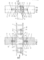
- FIG. 1 shows a section through a node formed by two columns and a support arranged one above the other
- FIG. 2 shows a view in the direction II according to FIG. 1.
- Fig. 1 shows two superimposed, prefabricated concrete columns 1, 2, of which the lower concrete column 1 on its upper end face and the upper concrete column 2 on its lower end face has an axial recess 3 or 4, which is cylindrical and preferably with a socket is lined.
- each concrete column 1, 2 is provided in the end region with a through opening 5 and 6, which runs transversely to the longitudinal axis, the purpose of which is explained later.
- the reference numeral 7 designates a lattice girder whose width is less than the column width (see FIG. 2) and which extends over at least three concrete columns 1, 2 standing side by side in a row. If the concrete columns 1, 2 are set up at equal intervals, the length of the support 7 is two or more times the simple column interval.
- ceiling beams 8 are inserted and firmly connected to the support 7, for example by means of cross holes 9 and rods 10 which are welded to the support 7. Ceiling panels (not shown) are later placed on the ceiling beams 8.
- a rod 11 In the recess 3 of the lower concrete column 1 there is a rod 11, the dimensions of which correspond to those of the recess 3 or possibly the socket.
- This rod 11 is firmly connected to a plate 12, the size of which preferably corresponds to the cross section of the concrete column 1 and in the corner regions of which one foot in the form of an angle profile 13 is attached upright.
- the rod 11, the plate 12 and the angle sections 13 are welded to steel components and.
- the plates 17 connected to the feet or angle profiles 18 of the upper part 15 can be smaller than the lower plate 12 and in any case carries on its upper side a rod 16 with the recess 4 of the upper concrete column 2 adapted dimensions.
- the width of the truss 7 is not only smaller than that of the concrete columns 1, 2, but also less than the smallest distance between the angle profiles 18 of the second, inserted part of the connecting element.
- the truss 7 can therefore pass through at the connection points of the concrete columns 1, 2.
- first several (at least three) lower, prefabricated concrete columns 1 are set up and in each of their front recesses 3 a lower part 14 of the connecting element with the rod 11 is inserted.
- Each rod 11 is provided with a bore 19 at a distance from the plate 12 corresponding to the distance of the through opening of the concrete column 1 from its end face; when inserting the rod 11 into the recess 3, this bore 19 is brought into alignment with the through opening 3, after which a wedge is introduced into the through opening 3 and the bore 19, with which the lower part 14 of the connecting element is fixed with respect to the concrete column 1.
- a truss girder 7 reaching over several concrete pillars 1 is placed on the concrete pillars 1, resting on the plates 12 of the lower parts 14 of the connecting elements and being arranged between their angle profiles 13.
- the upper parts 15 of the connecting elements are put on, overlapping the truss 7. Furthermore, the plates 17 of the upper parts 15 can rest on the truss' 7; since the knot is ultimately potted with concrete; however, this is not necessary.
- the two parts 14, 15 of the connecting elements in the illustrated embodiment by welding the angle profiles 13 and 18, are firmly connected to one another.
- the ceiling beams 8 are inserted into the trusses 7 and onto the above discussed way fixed.
- the upper concrete columns 2 with their recesses 4 are now placed on the rods 16 of the upper parts 15 of the connecting elements.
- the rods 16 of the upper parts 15 also have bores 20 aligned with the through openings 6 of the upper concrete columns 2, which are used for fixing by means of wedges - as described above. Finally, the remaining concreting work is carried out.
- the invention thus provides a construction with which a considerable reduction in working hours can be achieved at the construction site due to the beams extending over several columns, while at the same time an exact centering of the columns arranged one above the other is achieved.
- one or both parts of the connecting element can be anchored in the respective concrete column by pouring. However, because of the risk of damage to these parts mentioned at the outset, it is preferred to attach the parts to the concrete pillars only at the construction site and not during the prefabrication thereof, which is, however, quite possible.
Landscapes
- Engineering & Computer Science (AREA)
- Architecture (AREA)
- Physics & Mathematics (AREA)
- Electromagnetism (AREA)
- Civil Engineering (AREA)
- Structural Engineering (AREA)
- Joining Of Building Structures In Genera (AREA)
Applications Claiming Priority (2)
| Application Number | Priority Date | Filing Date | Title |
|---|---|---|---|
| AT0310784A AT381526B (de) | 1984-10-01 | 1984-10-01 | Bauweise fuer hoch-, insbesondere skelettbauten |
| AT3107/84 | 1984-10-01 |
Publications (2)
| Publication Number | Publication Date |
|---|---|
| EP0177483A2 true EP0177483A2 (fr) | 1986-04-09 |
| EP0177483A3 EP0177483A3 (fr) | 1988-01-27 |
Family
ID=3545407
Family Applications (1)
| Application Number | Title | Priority Date | Filing Date |
|---|---|---|---|
| EP85890236A Withdrawn EP0177483A3 (fr) | 1984-10-01 | 1985-09-26 | Mode d'exécution pour des bâtiments de grande hauteur en particulier pour des constructions en ossature |
Country Status (2)
| Country | Link |
|---|---|
| EP (1) | EP0177483A3 (fr) |
| AT (1) | AT381526B (fr) |
Cited By (2)
| Publication number | Priority date | Publication date | Assignee | Title |
|---|---|---|---|---|
| DE10247388A1 (de) * | 2002-10-07 | 2004-04-22 | Unterberg, Hartmut, Dipl.-Ing. (FH) | Standardisierte Tragstruktur für ein- und mehrgeschossige Gebäude |
| CN110306785A (zh) * | 2019-07-25 | 2019-10-08 | 河南绿建建筑科技有限公司 | 钢砼组合剪力墙t型节点浇筑模板架 |
Families Citing this family (1)
| Publication number | Priority date | Publication date | Assignee | Title |
|---|---|---|---|---|
| CN108789787B (zh) * | 2018-06-03 | 2022-08-12 | 重庆工业职业技术学院 | 高强度装配式建筑的高效构造方法 |
Family Cites Families (7)
| Publication number | Priority date | Publication date | Assignee | Title |
|---|---|---|---|---|
| AT222308B (de) * | 1959-07-07 | 1962-07-10 | Miroslav Ing Capek | Montierter Skelettrahmen aus armiertem Beton |
| AT230592B (de) * | 1961-03-06 | 1963-12-10 | Stefan Herzy | Bauweise für Hoch- insbesondere Skelettbauten |
| AT235531B (de) * | 1962-11-06 | 1964-09-10 | Stefan Herzy | Verfahren zur Herstellung von Trägerdecken |
| GB1211717A (en) * | 1967-11-28 | 1970-11-11 | Dyna Structures | Structural frames |
| CH494869A (de) * | 1969-02-05 | 1970-08-15 | Huonder Anton | Verbindungsvorrichtung für Bauelemente |
| AU485203B2 (en) * | 1971-11-23 | 1974-03-28 | Dowsett Engineering (Australia) Pty. Limited | Interconnecting structural elements |
| EP0079413A1 (fr) * | 1981-11-16 | 1983-05-25 | Geilinger AG | Disposition de la liaison des poteaux d'un bâtiment |
-
1984
- 1984-10-01 AT AT0310784A patent/AT381526B/de not_active IP Right Cessation
-
1985
- 1985-09-26 EP EP85890236A patent/EP0177483A3/fr not_active Withdrawn
Cited By (3)
| Publication number | Priority date | Publication date | Assignee | Title |
|---|---|---|---|---|
| DE10247388A1 (de) * | 2002-10-07 | 2004-04-22 | Unterberg, Hartmut, Dipl.-Ing. (FH) | Standardisierte Tragstruktur für ein- und mehrgeschossige Gebäude |
| CN110306785A (zh) * | 2019-07-25 | 2019-10-08 | 河南绿建建筑科技有限公司 | 钢砼组合剪力墙t型节点浇筑模板架 |
| CN110306785B (zh) * | 2019-07-25 | 2024-05-17 | 河南绿建建筑科技有限公司 | 钢砼组合剪力墙t型节点浇筑模板架 |
Also Published As
| Publication number | Publication date |
|---|---|
| AT381526B (de) | 1986-10-27 |
| ATA310784A (de) | 1986-03-15 |
| EP0177483A3 (fr) | 1988-01-27 |
Similar Documents
| Publication | Publication Date | Title |
|---|---|---|
| EP0073733B1 (fr) | Poutre en forme de treillis pour le soutènement de galeries et puits souterrains | |
| EP1931832A2 (fr) | Poteau mixte destine a des raccords a goussets de batiments et structure de batiment | |
| EP0752033B1 (fr) | Structure constituee d'elements prefabriques | |
| DE3432940A1 (de) | Vorgefertigtes mauerwerk | |
| EP0177483A2 (fr) | Mode d'exécution pour des bâtiments de grande hauteur en particulier pour des constructions en ossature | |
| DE3716833A1 (de) | Verfahren zur herstellung von vorgespannten stahltraegern, sowie die hierdurch erhaltenen traeger | |
| DE3941313A1 (de) | Verbundstruktur fuer einen unterzug zur abstuetzung einer aufrechtstehenden wand | |
| DE3704900C2 (fr) | ||
| DE19941603C2 (de) | Stahlbetonteil zur Herstellung von Fundamenten für Bauwerke | |
| DE60304547T2 (de) | Vorgefertigte Stahlbetonsäule und Stahlbetonträger | |
| DE1998231U (de) | Wandelemente zum errichten von gebaueden und dergleichen | |
| EP3725975B1 (fr) | Procédé de fabrication d'un module de parc de stationnement | |
| DE2912131C2 (de) | Garage | |
| DE29915343U1 (de) | Stahlbetonteil zur Herstellung von Fundamenten für Bauwerke | |
| DE2548298C2 (de) | Verfahren und Hohlraumverschalungswand zum Bauen einer Hohlmauer | |
| DE69613978T2 (de) | Verbindung von betonbauelementen | |
| AT399003B (de) | Trägerrost zum dachbodenausbau oder zur hallenerrichtung | |
| AT406592B (de) | Tragkonstruktion für bauwerke | |
| DE202005006228U1 (de) | Dachkonstruktion für Gebäude, insbesondere für Industriegebäude mit großen Spannweiten | |
| DE3513624A1 (de) | Transportables bauwerk | |
| DE1817877C3 (de) | Verfahren zum Herstellen eines transportablen Baumelementes für die Errichtung von Bauwerken | |
| DE2750931C2 (fr) | ||
| DE4012532A1 (de) | Verfahren zum herstellen eines betonkoerpers fuer bauwerke oder bauwerksteile sowie hierfuer geeignetes betonfertigelement | |
| DE2720042A1 (de) | Verbindung eines balkens mit einer saeule | |
| EP4194613A1 (fr) | Module de fabrication d'une fondation en béton, utilisation et procédé |
Legal Events
| Date | Code | Title | Description |
|---|---|---|---|
| PUAI | Public reference made under article 153(3) epc to a published international application that has entered the european phase |
Free format text: ORIGINAL CODE: 0009012 |
|
| AK | Designated contracting states |
Kind code of ref document: A2 Designated state(s): BE CH DE FR GB IT LI LU NL SE |
|
| PUAL | Search report despatched |
Free format text: ORIGINAL CODE: 0009013 |
|
| AK | Designated contracting states |
Kind code of ref document: A3 Designated state(s): BE CH DE FR GB IT LI LU NL SE |
|
| RHK1 | Main classification (correction) |
Ipc: E04B 1/56 |
|
| STAA | Information on the status of an ep patent application or granted ep patent |
Free format text: STATUS: THE APPLICATION IS DEEMED TO BE WITHDRAWN |
|
| 18D | Application deemed to be withdrawn |
Effective date: 19880728 |