EP0177672B1 - Assemblage de disque de frein pour frein à disque à prise interne, en particulier pour automobiles - Google Patents
Assemblage de disque de frein pour frein à disque à prise interne, en particulier pour automobiles Download PDFInfo
- Publication number
- EP0177672B1 EP0177672B1 EP85107182A EP85107182A EP0177672B1 EP 0177672 B1 EP0177672 B1 EP 0177672B1 EP 85107182 A EP85107182 A EP 85107182A EP 85107182 A EP85107182 A EP 85107182A EP 0177672 B1 EP0177672 B1 EP 0177672B1
- Authority
- EP
- European Patent Office
- Prior art keywords
- brake disc
- brake
- ring
- connecting element
- arrangement
- Prior art date
- Legal status (The legal status is an assumption and is not a legal conclusion. Google has not performed a legal analysis and makes no representation as to the accuracy of the status listed.)
- Expired
Links
Images



Classifications
-
- B—PERFORMING OPERATIONS; TRANSPORTING
- B60—VEHICLES IN GENERAL
- B60T—VEHICLE BRAKE CONTROL SYSTEMS OR PARTS THEREOF; BRAKE CONTROL SYSTEMS OR PARTS THEREOF, IN GENERAL; ARRANGEMENT OF BRAKING ELEMENTS ON VEHICLES IN GENERAL; PORTABLE DEVICES FOR PREVENTING UNWANTED MOVEMENT OF VEHICLES; VEHICLE MODIFICATIONS TO FACILITATE COOLING OF BRAKES
- B60T1/00—Arrangements of braking elements, i.e. of those parts where braking effect occurs specially for vehicles
- B60T1/02—Arrangements of braking elements, i.e. of those parts where braking effect occurs specially for vehicles acting by retarding wheels
- B60T1/06—Arrangements of braking elements, i.e. of those parts where braking effect occurs specially for vehicles acting by retarding wheels acting otherwise than on tread, e.g. employing rim, drum, disc, or transmission or on double wheels
- B60T1/065—Arrangements of braking elements, i.e. of those parts where braking effect occurs specially for vehicles acting by retarding wheels acting otherwise than on tread, e.g. employing rim, drum, disc, or transmission or on double wheels employing disc
-
- F—MECHANICAL ENGINEERING; LIGHTING; HEATING; WEAPONS; BLASTING
- F16—ENGINEERING ELEMENTS AND UNITS; GENERAL MEASURES FOR PRODUCING AND MAINTAINING EFFECTIVE FUNCTIONING OF MACHINES OR INSTALLATIONS; THERMAL INSULATION IN GENERAL
- F16D—COUPLINGS FOR TRANSMITTING ROTATION; CLUTCHES; BRAKES
- F16D65/00—Parts or details
- F16D65/02—Braking members; Mounting thereof
- F16D65/12—Discs; Drums for disc brakes
- F16D65/123—Discs; Drums for disc brakes comprising an annular disc secured to a hub member; Discs characterised by means for mounting
-
- F—MECHANICAL ENGINEERING; LIGHTING; HEATING; WEAPONS; BLASTING
- F16—ENGINEERING ELEMENTS AND UNITS; GENERAL MEASURES FOR PRODUCING AND MAINTAINING EFFECTIVE FUNCTIONING OF MACHINES OR INSTALLATIONS; THERMAL INSULATION IN GENERAL
- F16D—COUPLINGS FOR TRANSMITTING ROTATION; CLUTCHES; BRAKES
- F16D55/00—Brakes with substantially-radial braking surfaces pressed together in axial direction, e.g. disc brakes
- F16D2055/0004—Parts or details of disc brakes
- F16D2055/005—Brakes straddling an annular brake disc radially internally
-
- F—MECHANICAL ENGINEERING; LIGHTING; HEATING; WEAPONS; BLASTING
- F16—ENGINEERING ELEMENTS AND UNITS; GENERAL MEASURES FOR PRODUCING AND MAINTAINING EFFECTIVE FUNCTIONING OF MACHINES OR INSTALLATIONS; THERMAL INSULATION IN GENERAL
- F16D—COUPLINGS FOR TRANSMITTING ROTATION; CLUTCHES; BRAKES
- F16D65/00—Parts or details
- F16D65/02—Braking members; Mounting thereof
- F16D2065/13—Parts or details of discs or drums
- F16D2065/1304—Structure
- F16D2065/1316—Structure radially segmented
-
- F—MECHANICAL ENGINEERING; LIGHTING; HEATING; WEAPONS; BLASTING
- F16—ENGINEERING ELEMENTS AND UNITS; GENERAL MEASURES FOR PRODUCING AND MAINTAINING EFFECTIVE FUNCTIONING OF MACHINES OR INSTALLATIONS; THERMAL INSULATION IN GENERAL
- F16D—COUPLINGS FOR TRANSMITTING ROTATION; CLUTCHES; BRAKES
- F16D65/00—Parts or details
- F16D65/02—Braking members; Mounting thereof
- F16D2065/13—Parts or details of discs or drums
- F16D2065/1304—Structure
- F16D2065/1328—Structure internal cavities, e.g. cooling channels
-
- F—MECHANICAL ENGINEERING; LIGHTING; HEATING; WEAPONS; BLASTING
- F16—ENGINEERING ELEMENTS AND UNITS; GENERAL MEASURES FOR PRODUCING AND MAINTAINING EFFECTIVE FUNCTIONING OF MACHINES OR INSTALLATIONS; THERMAL INSULATION IN GENERAL
- F16D—COUPLINGS FOR TRANSMITTING ROTATION; CLUTCHES; BRAKES
- F16D65/00—Parts or details
- F16D65/02—Braking members; Mounting thereof
- F16D2065/13—Parts or details of discs or drums
- F16D2065/134—Connection
- F16D2065/1344—Connection permanent, e.g. by casting
-
- F—MECHANICAL ENGINEERING; LIGHTING; HEATING; WEAPONS; BLASTING
- F16—ENGINEERING ELEMENTS AND UNITS; GENERAL MEASURES FOR PRODUCING AND MAINTAINING EFFECTIVE FUNCTIONING OF MACHINES OR INSTALLATIONS; THERMAL INSULATION IN GENERAL
- F16D—COUPLINGS FOR TRANSMITTING ROTATION; CLUTCHES; BRAKES
- F16D65/00—Parts or details
- F16D65/02—Braking members; Mounting thereof
- F16D2065/13—Parts or details of discs or drums
- F16D2065/134—Connection
- F16D2065/1356—Connection interlocking
-
- F—MECHANICAL ENGINEERING; LIGHTING; HEATING; WEAPONS; BLASTING
- F16—ENGINEERING ELEMENTS AND UNITS; GENERAL MEASURES FOR PRODUCING AND MAINTAINING EFFECTIVE FUNCTIONING OF MACHINES OR INSTALLATIONS; THERMAL INSULATION IN GENERAL
- F16D—COUPLINGS FOR TRANSMITTING ROTATION; CLUTCHES; BRAKES
- F16D65/00—Parts or details
- F16D65/02—Braking members; Mounting thereof
- F16D2065/13—Parts or details of discs or drums
- F16D2065/134—Connection
- F16D2065/1372—Connection outer circumference
-
- F—MECHANICAL ENGINEERING; LIGHTING; HEATING; WEAPONS; BLASTING
- F16—ENGINEERING ELEMENTS AND UNITS; GENERAL MEASURES FOR PRODUCING AND MAINTAINING EFFECTIVE FUNCTIONING OF MACHINES OR INSTALLATIONS; THERMAL INSULATION IN GENERAL
- F16D—COUPLINGS FOR TRANSMITTING ROTATION; CLUTCHES; BRAKES
- F16D65/00—Parts or details
- F16D65/02—Braking members; Mounting thereof
- F16D2065/13—Parts or details of discs or drums
- F16D2065/134—Connection
- F16D2065/1392—Connection elements
-
- F—MECHANICAL ENGINEERING; LIGHTING; HEATING; WEAPONS; BLASTING
- F16—ENGINEERING ELEMENTS AND UNITS; GENERAL MEASURES FOR PRODUCING AND MAINTAINING EFFECTIVE FUNCTIONING OF MACHINES OR INSTALLATIONS; THERMAL INSULATION IN GENERAL
- F16D—COUPLINGS FOR TRANSMITTING ROTATION; CLUTCHES; BRAKES
- F16D2250/00—Manufacturing; Assembly
- F16D2250/0007—Casting
- F16D2250/0015—Casting around inserts
-
- F—MECHANICAL ENGINEERING; LIGHTING; HEATING; WEAPONS; BLASTING
- F16—ENGINEERING ELEMENTS AND UNITS; GENERAL MEASURES FOR PRODUCING AND MAINTAINING EFFECTIVE FUNCTIONING OF MACHINES OR INSTALLATIONS; THERMAL INSULATION IN GENERAL
- F16D—COUPLINGS FOR TRANSMITTING ROTATION; CLUTCHES; BRAKES
- F16D2250/00—Manufacturing; Assembly
- F16D2250/0061—Joining
- F16D2250/0076—Welding, brazing
-
- F—MECHANICAL ENGINEERING; LIGHTING; HEATING; WEAPONS; BLASTING
- F16—ENGINEERING ELEMENTS AND UNITS; GENERAL MEASURES FOR PRODUCING AND MAINTAINING EFFECTIVE FUNCTIONING OF MACHINES OR INSTALLATIONS; THERMAL INSULATION IN GENERAL
- F16D—COUPLINGS FOR TRANSMITTING ROTATION; CLUTCHES; BRAKES
- F16D65/00—Parts or details
- F16D65/02—Braking members; Mounting thereof
- F16D65/12—Discs; Drums for disc brakes
- F16D65/128—Discs; Drums for disc brakes characterised by means for cooling
Definitions
- the invention relates to a brake disc arrangement for an internally encompassing disc brake, in particular for motor vehicles, according to the preamble of patent claim 1.
- Such a brake disc arrangement is known from GB-A-1 0 27 686.
- the sheet metal carrier consists of five segments, which are cast directly into the cast brake ring with their radially outer edge region.
- the cast brake ring has a radial extension that extends beyond the braking surfaces in the radial direction.
- This known arrangement has several disadvantages. These disadvantages consist, in particular, in that a lot of space is lost due to the radial extension of the cast brake ring, into which the outer edge of the sheet metal support segments is cast.
- a major advantage of disc brakes encompassing the inside, namely to create the largest possible friction radius is at least partially eliminated.
- the sheet metal support consists of individual support segments which are only connected via the cast brake ring, but have no connection to one another in their inner region. This of course significantly affects the stability of the entire arrangement, making the brake disc unsuitable for high-performance brakes. Further disadvantages result from the direct pouring of the sheet metal carrier into the cast brake ring, which is relatively complex in terms of production technology, since after the casting process, machining operations such as surface grinding on the cast brake ring must still take place.
- GB-A-1 312584 Another possibility of circumferentially fastening a brake disc is known from GB-A-1 312584.
- the brake disc has projections on its circumference, which protrude into interruptions on the circumference of a drum-shaped carrier and which slightly project beyond the outer diameter of the carrier.
- the brake disc is connected to the carrier via spring strips, which are attached to the circumference of the carrier by means of hexagon screws and press on the projections of the brake disc.
- the invention has for its object to improve a brake disc assembly of the type specified in the preamble of claim 1 in such a way that the largest possible friction radius can be achieved. i.e. in other words, the space available in the wheel is used as far as possible, especially in the radial direction.
- a brake disk arrangement is created which enables the greatest possible friction radius of the brake ring. Furthermore, the arrangement is inexpensive in terms of production technology in that it enables two finished parts, namely the cast brake ring on the one hand and the sheet metal support on the other hand, to be connected to one another so safely and without distortion that reworking after the welding operation is not necessary.
- the loss distance between the wheel rim and the effective outer diameter of the braking surface is as small as possible and is not impaired by the arrangement of space-consuming fastening devices.
- the sheet metal support according to the invention is considerably more stable than the known sheet metal support consisting of individual segments.
- the connecting element is of annular design, the outer circumferential surface forming at least one contact surface for the sheet metal carrier, which is formed in particular by a radial projection pointing outwards.
- the invention can be used with a brake disc, the brake ring for cooling of which consists of two axially spaced partial brake rings which are connected to one another via ribs or the like. If, according to a further embodiment of the invention, the intermediate element is arranged only in a partial brake ring, in particular facing the sheet metal support, there is the further advantage that the cooling channels of the brake ring are not covered by the sheet metal support and thus are not impaired in their cooling effect.
- the difference between the outside diameter of the connecting element and the friction ring essentially corresponds to the sheet thickness of the connecting element and is therefore in the range from about 1.5 to 5 mm, in particular at 2 to 3 mm.
- this can have reinforcing ribs or beads which extend essentially in the radial and / or circumferential direction and advantageously run continuously in at least two arms.
- the reinforcing ribs are preferably formed in the sheet metal carrier by means of pressing, stamping or deep drawing.
- the partial brake ring provided on this side has a larger diameter than the other partial brake ring to which the sheet metal carrier is attached.
- the connecting section of the sheet-metal brake disc carrier is formed by the end sections of a plurality of arms arranged in a star shape, or that the connecting section is cup-shaped all round and has at least one opening adjacent to the braking path for removing the brake lining.
- the connecting element has openings which extend essentially in the axial direction, in particular continuous bores.
- FIG. 1 shows an arrangement of an internally encompassing disc brake 2 in a vehicle wheel 4.
- the vehicle wheel 4 is fastened to a wheel bearing housing 12 by means of the bolt 10 via the wheel bowl 8.
- the vehicle wheel 4 is rotatably supported by means of the wheel bearing housing 12 via a bearing (not shown here) on an axle spindle connected to the steering knuckle (also not shown).
- the wheel bearing housing 12 has a flange 14 in which threaded bores 16 are provided, into which the screw bolts 10 are screwed.
- a brake disc carrier 18 is also fastened to the flange 14 with the screw bolts 10, the brake disc carrier 18 being arranged between the flange 14 and the wheel disc 8.
- the brake disc carrier 18 has a radially inner, essentially annular fastening section 20, in which bores 21 are provided for the passage of the bolts 10, and a carrier section 22 adapted to the contour of the wheel disc 8.
- the carrier section 22 forms one end - Or connecting section, which runs substantially axially parallel and to which a connecting element 24 is attached.
- a friction ring 26 is connected to the connecting element 24, which forms the actual brake disc and has two opposing friction surfaces for this purpose.
- the disc brake 2 encompassing the inside has a brake housing 28 which is essentially U-shaped in longitudinal section, it having two legs 30, 32 which extend radially outwards and are connected to one another via a bridge part 34. Brake pads 36, 38 are arranged on both sides of the friction ring 26 and are encompassed by the U-shaped brake housing 28.
- the inner leg 32 has a cylinder bore 40 in which a piston 42 is arranged to be axially displaceable.
- the piston 42 acts directly on the inner brake lining 38, as a result of which the brake housing 28 is displaced inwards in the opposite direction, and as a result the outer lining 36 is also acted on.
- the brake housing 28 is slidably mounted on a stationary brake carrier 50.
- the brake disc arrangement seen in an axial view in FIG. 2 has a brake disc carrier 18 which is made of sheet metal.
- the one-piece brake disc carrier 18 forms a central, essentially circular fastening section 20, from the outer circumference of which radially arranged arms 60 extend, each of which forms a curved carrier section 22 which is adapted to the contour of the wheel disc 8 and which extends into a carrier section 61 which extends essentially axially parallel (see also Fig. 1) passes.
- the carrier sections 61 end above the connecting element 24, which is cast into the friction ring 26 of the brake disc.
- the friction ring 26 shown here consists of two axially spaced partial friction rings 26a, 26b, which are connected to one another via ribs 62, with ventilation channels remaining in between.
- the inner partial friction ring 26a is made larger in diameter, as a result of which a larger friction surface is available on this side.
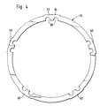
- the connecting element 24 On its outer circumference, the connecting element 24 has a number of projections 63 which extend radially outwards and correspond to the number of arms 60 (FIG. 4). on, which form contact surfaces 64 for the inner surfaces or carrier end or connecting sections 61.
- the connecting element 24 has through openings 65 which are open towards the inner edge and which are penetrated by the casting material when poured in.
- the weld seam 65 which is produced in particular by means of electron beam welding or another low-distortion welding process which has similar operating parameters, runs between these inner surfaces and the contact surfaces 64.
- the arms 60 of the brake disc carrier 18, which are arranged in a star shape, are dimensioned in such a way that there is sufficient strength or rigidity.
- the arrangement is selected such that a free space 66 remains through at least two arms, through which the outer brake pad 36 can be removed radially.
- the arms 60 are provided with reinforcing ribs or beads 66.
- reinforcing ribs extend at the edge of the arms 60 and can extend continuously from one arm via the fastening section 20 into at least one further arm 60.
- the brake disc carrier 18 is produced in a pressing, embossing or deep-drawing process, the reinforcing ribs 66 being formed at the same time.
- FIG. 5 shows a connecting segment 68 which can be used in a corresponding number instead of a continuous annular connecting element.
- FIG. 6 shows a section of an annular connecting element 71 with continuous closed bores 72 which are penetrated when material is being poured.
- Fig. 7 shows an arrangement with a cup-shaped or bowl-shaped sheet-metal brake disk carrier 69, which is largely closed. A correspondingly dimensioned opening or cutout 70 is provided for the radial removal of the brake lining in the area of the brake ring.
Landscapes
- Engineering & Computer Science (AREA)
- Mechanical Engineering (AREA)
- General Engineering & Computer Science (AREA)
- Transportation (AREA)
- Braking Arrangements (AREA)
Claims (16)
Applications Claiming Priority (2)
| Application Number | Priority Date | Filing Date | Title |
|---|---|---|---|
| DE3436973 | 1984-10-09 | ||
| DE19843436973 DE3436973A1 (de) | 1984-10-09 | 1984-10-09 | Bremsscheibenanordnung fuer eine innen umgreifende scheibenbremse, insbesondere fuer kraftfahrzeuge |
Publications (2)
| Publication Number | Publication Date |
|---|---|
| EP0177672A1 EP0177672A1 (fr) | 1986-04-16 |
| EP0177672B1 true EP0177672B1 (fr) | 1988-12-07 |
Family
ID=6247442
Family Applications (1)
| Application Number | Title | Priority Date | Filing Date |
|---|---|---|---|
| EP85107182A Expired EP0177672B1 (fr) | 1984-10-09 | 1985-06-11 | Assemblage de disque de frein pour frein à disque à prise interne, en particulier pour automobiles |
Country Status (2)
| Country | Link |
|---|---|
| EP (1) | EP0177672B1 (fr) |
| DE (2) | DE3436973A1 (fr) |
Families Citing this family (11)
| Publication number | Priority date | Publication date | Assignee | Title |
|---|---|---|---|---|
| DE3536465A1 (de) * | 1984-10-09 | 1987-04-16 | Teves Gmbh Alfred | Bremsscheibe, insbesondere fuer eine innen umgreifende scheibenbremse eines kraftfahrzeuges |
| DE3535288C2 (de) * | 1985-10-03 | 1994-07-14 | Teves Gmbh Alfred | Bremsscheibenanordnung für eine innen umgreifende Scheibenanordnung für Kraftfahrzeuge |
| DE3535290C2 (de) * | 1985-10-03 | 1994-07-07 | Teves Gmbh Alfred | Bremsscheibenanordnung für eine innen umgreifende Scheibenbremse, insbesondere für Kraftfahrzeuge |
| DE3612896A1 (de) * | 1986-04-17 | 1987-10-29 | Schwaebische Huettenwerke Gmbh | Bremsscheibenvorrichtung |
| US5264286A (en) * | 1988-03-03 | 1993-11-23 | Asahi Glass Company Ltd. | Laminated glass structure |
| DE4333517A1 (de) * | 1993-10-01 | 1995-04-06 | Buderus Guss Gmbh | Bremsscheibe für Scheibenbremsen |
| US5593005A (en) * | 1995-06-07 | 1997-01-14 | Itt Automotive, Inc. | Caliper-type disc brake with stepped rotor |
| DE50103573D1 (de) * | 2000-02-23 | 2004-10-21 | Bayerische Motoren Werke Ag | Verfahren zur Herstellung einer Bremsscheibe |
| DE10028532A1 (de) * | 2000-06-08 | 2001-12-13 | Bayerische Motoren Werke Ag | Fahrzeug-Bremsscheibe, deren Reibring und Bremsscheibentopf aus unterschiedlichen Werkstoffen bestehen |
| DE102017215992A1 (de) * | 2017-06-20 | 2018-12-20 | Continental Teves Ag & Co. Ohg | Radeinheit für Kraftfahrzeuge |
| CN114056297B (zh) * | 2022-01-12 | 2022-04-12 | 中车戚墅堰机车车辆工艺研究所有限公司 | 一种车用液压制动控制系统 |
Family Cites Families (15)
| Publication number | Priority date | Publication date | Assignee | Title |
|---|---|---|---|---|
| US2655227A (en) * | 1950-07-29 | 1953-10-13 | Budd Co | Disk brake |
| FR1177067A (fr) * | 1957-05-29 | 1959-04-20 | Alford & Alder Engineers Ltd | Perfectionnements aux disques pour freins |
| US3077954A (en) * | 1959-07-14 | 1963-02-19 | Ford Motor Co | Disc brake |
| DE1161158B (de) * | 1960-04-06 | 1964-01-09 | Porsche Kg | Scheibenbremse fuer Fahrzeuge, insbesondere fuer Kraftfahrzeuge |
| GB1027686A (en) * | 1962-04-03 | 1966-04-27 | Girling Ltd | Improvements in disc brakes |
| FR1412466A (fr) * | 1964-07-27 | 1965-10-01 | Rech Etudes Prod | Frein à disque pour roue |
| DE1974457U (de) * | 1967-09-09 | 1967-12-07 | Porsche Kg | Bremsscheiben fuer scheibenbremsen, insbesondere fuer kraftfahrzeuge. |
| DE1941904A1 (de) * | 1969-08-18 | 1971-03-04 | Ewald Bous | Rechenschieber |
| GB1333561A (en) * | 1970-01-13 | 1973-10-10 | Girling Ltd | Rotors of disc brakes |
| FR2094279A5 (fr) * | 1970-06-16 | 1972-02-04 | Pont A Mousson | |
| GB1339664A (en) * | 1971-05-19 | 1973-12-05 | Rickwood P | Vehicle brakes |
| FR2248743A5 (en) * | 1973-10-19 | 1975-05-16 | Pont A Mousson | Multi-section disc for disc brakes - has tapered clamping wedge ensuring correct alignment of annular sections during clamping |
| FR2357789A1 (fr) * | 1976-07-07 | 1978-02-03 | Pont A Mousson | Disque pour frein a disque |
| CA1082113A (fr) * | 1977-10-31 | 1980-07-22 | Goodbary Equipment Company | Frein a disque |
| SE7904523L (sv) * | 1979-05-23 | 1980-11-24 | Sab Ind Ab | Skivbromsarrangemang for ett relsfordon |
-
1984
- 1984-10-09 DE DE19843436973 patent/DE3436973A1/de not_active Ceased
-
1985
- 1985-06-11 DE DE8585107182T patent/DE3566717D1/de not_active Expired
- 1985-06-11 EP EP85107182A patent/EP0177672B1/fr not_active Expired
Also Published As
| Publication number | Publication date |
|---|---|
| DE3436973A1 (de) | 1986-04-17 |
| DE3566717D1 (en) | 1989-01-12 |
| EP0177672A1 (fr) | 1986-04-16 |
Similar Documents
| Publication | Publication Date | Title |
|---|---|---|
| DE2548927C2 (de) | Führung für den Sattel einer Schwimmsattel-Teilbelag-Scheibenbremse für Fahrzeuge | |
| EP3033540B1 (fr) | Disque de frein pour véhicule | |
| DE60112336T2 (de) | Radhalter für fahrzeuge mit scheibenbremsen | |
| EP0177672B1 (fr) | Assemblage de disque de frein pour frein à disque à prise interne, en particulier pour automobiles | |
| DD297215A5 (de) | Teilbelag-scheibenbremse | |
| DE2355821A1 (de) | Lagereinheit | |
| EP0023881A2 (fr) | Roue pour véhicule utilitaire pour assemblage simple ou jumelé | |
| DE2449043B2 (de) | Bremsscheibenanordnung, insbesondere für Gleisfahrzeuge | |
| DE10323310A1 (de) | Bremsscheibeneinheit | |
| DE3017307A1 (de) | Scheibenbremse | |
| DE3535290C2 (de) | Bremsscheibenanordnung für eine innen umgreifende Scheibenbremse, insbesondere für Kraftfahrzeuge | |
| DE3839957A1 (de) | Teilbelag-scheibenbremse | |
| DE3322232A1 (de) | Kombinierter aluminium/eisen-scheibenbremssattel | |
| DE2740326A1 (de) | Torsionsscheibe fuer zangenscheibenbremsen | |
| DE2942151A1 (de) | Bremsscheibe fuer scheibenbremsen | |
| WO1987003349A1 (fr) | Frein a disque a garniture partielle pour vehicules a moteur | |
| DE19906798A1 (de) | Radialkolbenbremse | |
| DE10033894A1 (de) | Demontagevorrichtung für ein selbsteinstellendes Lager | |
| DE3539602A1 (de) | Innenumgreifende scheibenbremse, insbesondere fuer kraftfahrzeuge | |
| DE2302455A1 (de) | Aus einem umlaufenden, zu bremsenden traeger und wenigstens einer an diesem festen bremsscheibe bestehende vorrichtung, insbesondere eisenbahnwagenrad | |
| DE1202153B (de) | Teilbelagscheibenbremse fuer Kraftfahrzeuge | |
| DE2721707A1 (de) | Trommelbremse sowie bremsbacke hierfuer | |
| EP1903248A1 (fr) | Disque de frein | |
| DE1139761B (de) | Innenbackenbremse, insbesondere fuer Kraftfahrzeuge | |
| DE3048062C2 (de) | Felgenanordnung |
Legal Events
| Date | Code | Title | Description |
|---|---|---|---|
| PUAI | Public reference made under article 153(3) epc to a published international application that has entered the european phase |
Free format text: ORIGINAL CODE: 0009012 |
|
| 17P | Request for examination filed |
Effective date: 19850611 |
|
| AK | Designated contracting states |
Kind code of ref document: A1 Designated state(s): DE FR GB IT |
|
| 17Q | First examination report despatched |
Effective date: 19870723 |
|
| ITF | It: translation for a ep patent filed | ||
| GRAA | (expected) grant |
Free format text: ORIGINAL CODE: 0009210 |
|
| AK | Designated contracting states |
Kind code of ref document: B1 Designated state(s): DE FR GB IT |
|
| GBT | Gb: translation of ep patent filed (gb section 77(6)(a)/1977) | ||
| REF | Corresponds to: |
Ref document number: 3566717 Country of ref document: DE Date of ref document: 19890112 |
|
| ET | Fr: translation filed | ||
| PLBE | No opposition filed within time limit |
Free format text: ORIGINAL CODE: 0009261 |
|
| STAA | Information on the status of an ep patent application or granted ep patent |
Free format text: STATUS: NO OPPOSITION FILED WITHIN TIME LIMIT |
|
| 26N | No opposition filed | ||
| ITTA | It: last paid annual fee | ||
| PGFP | Annual fee paid to national office [announced via postgrant information from national office to epo] |
Ref country code: GB Payment date: 19950517 Year of fee payment: 11 |
|
| PGFP | Annual fee paid to national office [announced via postgrant information from national office to epo] |
Ref country code: FR Payment date: 19950602 Year of fee payment: 11 |
|
| PG25 | Lapsed in a contracting state [announced via postgrant information from national office to epo] |
Ref country code: GB Effective date: 19960611 |
|
| GBPC | Gb: european patent ceased through non-payment of renewal fee |
Effective date: 19960611 |
|
| PG25 | Lapsed in a contracting state [announced via postgrant information from national office to epo] |
Ref country code: FR Effective date: 19970228 |
|
| REG | Reference to a national code |
Ref country code: FR Ref legal event code: ST |
|
| PGFP | Annual fee paid to national office [announced via postgrant information from national office to epo] |
Ref country code: DE Payment date: 19990630 Year of fee payment: 15 |
|
| PG25 | Lapsed in a contracting state [announced via postgrant information from national office to epo] |
Ref country code: DE Free format text: LAPSE BECAUSE OF NON-PAYMENT OF DUE FEES Effective date: 20010403 |