EP0177676A2 - Verfahren zur Prozesseinstellung mit Wärmerückgewinnung für die Sumpfphasehydrierung mit integrierter Gasphasehydrierung - Google Patents
Verfahren zur Prozesseinstellung mit Wärmerückgewinnung für die Sumpfphasehydrierung mit integrierter Gasphasehydrierung Download PDFInfo
- Publication number
- EP0177676A2 EP0177676A2 EP85107962A EP85107962A EP0177676A2 EP 0177676 A2 EP0177676 A2 EP 0177676A2 EP 85107962 A EP85107962 A EP 85107962A EP 85107962 A EP85107962 A EP 85107962A EP 0177676 A2 EP0177676 A2 EP 0177676A2
- Authority
- EP
- European Patent Office
- Prior art keywords
- gas phase
- mash
- hydrogenation
- phase hydrogenation
- temperature
- Prior art date
- Legal status (The legal status is an assumption and is not a legal conclusion. Google has not performed a legal analysis and makes no representation as to the accuracy of the status listed.)
- Granted
Links
- 238000005984 hydrogenation reaction Methods 0.000 title claims abstract description 45
- 238000000034 method Methods 0.000 title claims abstract description 15
- 239000000725 suspension Substances 0.000 title 1
- 239000007789 gas Substances 0.000 claims abstract description 51
- 238000010438 heat treatment Methods 0.000 claims abstract description 13
- 239000002918 waste heat Substances 0.000 claims abstract description 9
- 239000003054 catalyst Substances 0.000 claims abstract description 7
- 238000011084 recovery Methods 0.000 claims abstract description 5
- 239000000463 material Substances 0.000 claims 1
- 239000000126 substance Substances 0.000 claims 1
- 230000009849 deactivation Effects 0.000 abstract description 3
- 238000011109 contamination Methods 0.000 abstract 1
- 238000001816 cooling Methods 0.000 description 4
- 239000002904 solvent Substances 0.000 description 3
- 239000007788 liquid Substances 0.000 description 2
- 239000000203 mixture Substances 0.000 description 2
- 230000000750 progressive effect Effects 0.000 description 2
- 238000011144 upstream manufacturing Methods 0.000 description 2
- 238000009835 boiling Methods 0.000 description 1
- 230000005494 condensation Effects 0.000 description 1
- 238000009833 condensation Methods 0.000 description 1
- 238000010574 gas phase reaction Methods 0.000 description 1
- 239000007858 starting material Substances 0.000 description 1
Images
Classifications
-
- C—CHEMISTRY; METALLURGY
- C10—PETROLEUM, GAS OR COKE INDUSTRIES; TECHNICAL GASES CONTAINING CARBON MONOXIDE; FUELS; LUBRICANTS; PEAT
- C10G—CRACKING HYDROCARBON OILS; PRODUCTION OF LIQUID HYDROCARBON MIXTURES, e.g. BY DESTRUCTIVE HYDROGENATION, OLIGOMERISATION, POLYMERISATION; RECOVERY OF HYDROCARBON OILS FROM OIL-SHALE, OIL-SAND, OR GASES; REFINING MIXTURES MAINLY CONSISTING OF HYDROCARBONS; REFORMING OF NAPHTHA; MINERAL WAXES
- C10G1/00—Production of liquid hydrocarbon mixtures from oil-shale, oil-sand, or non-melting solid carbonaceous or similar materials, e.g. wood, coal
- C10G1/002—Production of liquid hydrocarbon mixtures from oil-shale, oil-sand, or non-melting solid carbonaceous or similar materials, e.g. wood, coal in combination with oil conversion- or refining processes
Definitions
- the temperature of the gas phase feedstocks has to be raised (e.g. from 390 ° C. to 430 ° C.). After all, the system should be able to be started up quickly - if possible without additional heating capacity.
- the invention is based, to ensure despite the variable heat output of the mash heat exchanger, an adjustment of the desired temperatures for the mash, the intermediate separator and the gas phase feedstocks and to achieve an economical heat recovery of the hydrogenation products. Furthermore, starting the plant should not require an additional heating furnace for the gas phase hydrogenation.
- the temperature of the gas phase feedstocks must gradually be raised. This takes place - without an additional heating furnace - according to the invention in that the temperature level of the head cooler upstream of the intermediate separator is also increased as the mash heat exchanger progresses. At the same time, with increasing reduction in the heat transfer capacity of the mash heat exchanger, the waste heat generated from the bottom phase hydrogenation is transferred to the upstream mash preheating of the bottom phase hydrogenation via the path of gas phase hydrogenation and thus used economically.
- the desired temperature in the intermediate separator is set by means of a final cooler, in which steam is expediently generated or hydrogenation gas is preheated.
- the temperature level of the bottom phase gases / vapors entering the mash heat exchanger can also be reduced. This reduces the usual fast incrustation of clean pipes of the mash heat exchanger, since the max. occurring mash temperature (at the same averaged mash outlet temperature) is reduced.
- the bypass around the mash heat exchanger serves to limit the max. Mash outlet temperature of the mash heat exchanger (especially when the heat exchanger tubes are clean).
- the start-up process is carried out quickly by heating the gas phase feedstocks using a head cooler behind the bottom phase hydrogenation.
- the process is explained in more detail using two examples:
- the gaseous and vaporous products from the bottom phase reactor 4 are partially cooled by means of mash heat exchanger 2 by indirect heat exchange, the mash-hydrogenation gas mixture being heated to the starting temperature of the bottom phase hydrogenation of approximately 440 ° C. on the heating side.
- the bottom phase products are further cooled by indirect heat exchange in the head cooler 7 and in the final cooler 8.
- the products from the bottom phase hydrogenation are divided into the solvent fraction (liquid) and the feed stream for the gas phase hydrogenation (gases / vapors). The latter is heated in the head cooler 7 and then in the indirect heat exchanger 10 to the gas phase reaction temperature of approximately 390 ° C.
- the gas phase products are partially cooled by indirect heat exchange in the mash heat exchanger 1, whereby the mash-hydrogenation gas mixture is preheated.
- the hydrogenation gas is preheated by further cooling of the gas phase products.
- the entire process is self-sufficient in stationary operation.
- the mash heating furnace 3 serves only as a start-up furnace.
- the gaseous and vaporous products from the hot separator 5 can be cooled somewhat before entering the mash preheater 2. In this way, the incrustation in the mash heat exchanger is reduced.
Landscapes
- Chemical & Material Sciences (AREA)
- Engineering & Computer Science (AREA)
- Oil, Petroleum & Natural Gas (AREA)
- Life Sciences & Earth Sciences (AREA)
- Wood Science & Technology (AREA)
- Chemical Kinetics & Catalysis (AREA)
- General Chemical & Material Sciences (AREA)
- Organic Chemistry (AREA)
- Production Of Liquid Hydrocarbon Mixture For Refining Petroleum (AREA)
- Organic Low-Molecular-Weight Compounds And Preparation Thereof (AREA)
- Industrial Gases (AREA)
Abstract
Description
- Die Erfindung betrifft die Prozeßeinstellung des kombinierten Sumpfphase-/Gasphase-Hydrierprozesses sowie die Wärmerückgewinnung der bei der Abkühlung und Kondensation der Produktströme aus der Sumpfphase-und Gasphasehydrierung nutzbaren Abwärme, welche zweckmäßig zum Aufheizen der beiden Einsatzstoffe des Sumpf- bzw. Gasphasereaktors verwendet wird.
- Bei einer derartigen Wärmerückgewinnung müssen die relevanten Prozeßparameter der Sumpfphasehydrierung mit integriertem Gasphasereaktor berücksichtigt werden.
- Zur Erhöhung der Wirtschaftlichkeit einer Hydrieranlage sind nach dem älteren Vorschlag die Sumpfphasehydrierung und die Gasphasehydrierung in einem gemeinsamen Hochdruckkreislauf angeordnet.
- Hierbei wird das Lösungsmittel zweckmäßig größtenteils im Sumpf eines Zwischenabscheiders hinter der Sumpfphasehydrierung abgezogen, so daß hauptsächlich nur die Nettoprodukte aus der Sumpfphasehydrierung (mit leichter und mittlerer Siedelage) über den nachgeschalteten Gasphasereaktor gefahren werden. Diese gewünschte Mengenaufsplittung der Sumpfphaseprodukte in Lösungsmittelanteil (flüssig) einerseits und Einsatzmenge für die Gasphasehydrierung (dampfförmig) andererseits erfolgt über eine definierte Temperatureinstellung im Zwischenabscheider hinter der Sumpfphasehydrierung.
- Diese Temperatureinstellung wird nun dadurch erschwert, daß der Maische-Wärmeaustauscher zur Maischeaufheizung durch indirekten Wärmeaustausch mittels abkühlender Sumpfphase-Gase/ Dämpfe mit fortschreitender Betriebszeit inkrustiert. Infolge der veränderlichen Wärmeübertragungsleistung des Maische-Wärmeaustauschers ist eine zusätzliche Kühlung erforderlich, um die erforderliche Temperatur und somit die gewünschte Mengenaufteilung im Zwischenabscheider zu erreichen. Auch ist bekannt, daß die Inkrustierung der Maischevorwärmer mit steigender Maischetemperatur zunimmt. Deshalb muß die Maischeaustrittstemperatur des Maische-Wärmeaustauschers nach oben hin begrenzt werden.
- Für die Sumpfphasehydrierung mit integriertem Gasphasenreaktor ist weiterhin zu berücksichtigen, daß mit zunehmender Desaktivierung des Gasphase-Katalysators die Temperatur der Gasphase-Einsatzstoffe angehoben werden muß (z. B. von 390 °C auf 430 °C). Schließlich soll die Anlage zügig - möglichst ohne zusätzliche Aufheizkapazitäten - anfahrbar sein.
- Der Erfindung liegt die Aufgabe zugrunde, trotz veränderlicher Wärmeleistung des Maische-Wärmeaustauschers eine Einstellung der gewünschten Temperaturen für die Maische, den Zwischenabscheider und die Gasphase-Einsatzstoffe zu gewährleisten sowie eine wirtschaftliche Wärmerückgewinnung der Hydrierprodukte zu erreichen. Weiterhin soll das Anfahren der Anlage keinen zusätzlichen Aufheizofen für die Gasphasehydrierung erfordern.
- Diese Aufgabe wird erfindungsgemäß dadurch gelöst, daß trotz veränderlicher Wärmeübertragungsleistung der Maische-Wärmeaustauscher (infolge fortschreitender Inkrustierung) und veränderlicher Gasphasereaktorparameter (infolge fortschreitender Katalysatordesaktivierung), die jeweils erforderlichen Prozeßtemperaturen für den Zwischenabscheider und den Gasphasereaktor mit Hilfe eines Kopfkühlers hinter der Sumpfphasehydrierung und eines Kopfkühlers vor dem Zwischenabscheider eingestellt werden. Der Kopfkühler hinter der Sumpfphasehydrierung dient gleichzeitig zum Anfahren der Gasphasehydrierung sowie zur Begrenzung der max. Maischeaustrittstemperatur des Maische-Wärmeaustauschers (ggf, mit Bypass).
- Mit zunehmender Laufzeit muß die Temperatur der Gasphase-Einsatzstoffe allmähl ich angehoben werden. Dies erfolgt - ohne zusätzlichen Aufheizofen - erfindungsgemäß dadurch, daß mit fortschreitender Inkrustierung des Maische-Wärmeaustauschers auch das Temperaturniveau des Kopfkühlers vor dem Zwischenabscheider angehoben wird. Gleichzeitig wird hierdurch - bei zunehmender Verringerung der Wärmeübertragungsleistung des Maische-Wärmeaustauschers - die anfallende Abwärme aus der Sumpfphasehydrierung über den Weg der Gasphasehydrierung auf die vorgeschaltete Maischevorwärmung der Sumpfphasehydrierung übertragen und damit wirtschaftlich genutzt.
- Die Einstellung der gewünschten Temperatur im Zwischenabscheider erfolgt mittels Schlußkühler, in welchem zweckmäßig Dampf erzeugt oder Hydriergas vorgewärmt wird.
- Mit dem Kopfkühler hinter der Sumpfphasehydrierung kann zusätzlich das Temperaturniveau der in den Maische-Wärmeaustauscher eintretenden Sumpfphase-Gase/Dämpfe reduziert werden. Hierdurch verringert sich die sonst übliche schnelle Inkrustierung von sauberen Rohren des Maische-Wärmeaustauschers, da die max. auftretende Maischetemperatur (bei gleicher gemittelter Maischeaustrittstemperatur) gesenkt wird.
- Mittels Kopfkühler (incl. Bypass) hinter der Sumpfphasehydrierung kann die gew+ünschte Temperatur der Einsatzstoffe der Gasphasehydrierung eingestellt werden.
- Der Bypass um den Maische-Wärmeaustauscher dient zur Begrenzung der max. Maischeaustrittstemperatur des Maische-Wärmeaustauschers (speziell im sauberen Zustand der Wärmeaustauscher-Rohre).
- Mit dem o.g. Verfahren können somit alle prozeßrelevanten Temperaturen - auch bei zeitlich unabhängig fortschreitender Verschmutzung der Maische-Wärmeaustauscher sowie Desaktivierung des Gasphase-Katalysators - eingestellt werden.
- Der Anfahrvorgang erfolgt zügig durch Aufheizung der Gasphase-Einsatzstoffe mittels Kopfkühler hinter der Sumpfphasehydrierung. An zwei Beispielen wird das Verfahren näher erläutert:
- In der Zeichnung sind zwei Ausführungsbeispiele der Erfindung dargestellt.
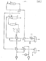
- Anhand von Fig. 1 wird ein Betriebsfall nach kurzer Laufzeit - d. h. nur geringe Inkrustierung der Maische-Wärmeaustauscher 1 und 2 sowie frischer Katalysator des Gasphase-Reaktors 11 - beschrieben.
- Die gas- und dampfförmigen Produkte aus dem Sumpfphase-Reaktor 4 werden mittels Maische-Wärmeaustauscher 2 durch indirekten Wärmeaustausch teilweise abgekühlt, wobei auf der Aufheizseite das Maische-Hydriergasgemisch auf Anspringtemperatur der Sumpfphasehydrierung von ca. 440 °C aufgeheizt wird. Zwecks Einstellung der prozeßtechnisch vorgegebenen Temperatur von ca. 300 °C im Zwischenabscheider 9 werden die Sumpfphaseprodukte durch indirekten Wärmeaustausch in dem Kopfkühler 7 und in dem Schlußkühler 8 weiter abgekühlt. Im Zwischenabscheider 9 werden die Produkte aus der Sumpfphasehydrierung in den Lösungsmittelanteil (flüssig) und in den Feedstrom für die Gasphasehydrierung (Gase/Dämpfe) aufgeteilt. Letzterer wird im Kopfkühler 7 und dann im indirekten Wärmeaustauscher 10 auf Gasphase-Reaktionstemperatur von ca. 390 °C aufgeheizt.
- Die gasphase-Produkte werden durch indirekten Wärmeaustausch im Maische-Wärmeaustauscher 1 teilweise abgekühlt, wodurch das Maische-Hydriergasgemisch vorgewärmt wird. Im indirekten Wärmeaustauscher 12 wird durch weitere Abkühlung der Gasphase-Produkte das Hydriergas vorgewärmt. Im stationären Betriebsfall ist der Gesamtprozeß wärmeautark. Der Maische-Aufheizofen 3 dient nur als Anfahrofen.
- Die Abwärme des Wärmeaustauschers 8 wird vorzugsweise zur Erzeugung von MD-Dampf oder zur Hydriergasvorwärmung verwendet.
- Mittels Kopfkühler 6 können die gas- und dampfförmigen Produkte aus dem Heißabscheider 5 vor Eintritt in den Maischevorwärmer 2 etwas abgekühlt werden. Auf diese Weise wird die Inkrustierung im Maische-Wärmeaustauscher reduziert.
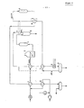
- Anhand von Fig. 2 wird ein Betriebsfall nach langer Laufzeit - d. h. starke Inkrustierung der Maische-Wärmeaustauscher 1 und 2 und desaktivierter Katalysator des Gasphase-Reaktors 11 - beschrieben.
- Infolge verminderter Wärmeübertragungsleistung des Maische-Wärmeaustauschers 2 wird die Feedtemperatur hinter dem Kopfkühler 7 gegenüber Beispiel 1 um ca. 20 °C angehoben. Die Gasphase-Eintrittstemperatur steigt auf ca. 425 °C an.
Claims (5)
Applications Claiming Priority (2)
| Application Number | Priority Date | Filing Date | Title |
|---|---|---|---|
| DE3433625 | 1984-09-13 | ||
| DE3433625 | 1984-09-13 |
Publications (3)
| Publication Number | Publication Date |
|---|---|
| EP0177676A2 true EP0177676A2 (de) | 1986-04-16 |
| EP0177676A3 EP0177676A3 (en) | 1988-03-02 |
| EP0177676B1 EP0177676B1 (de) | 1992-03-04 |
Family
ID=6245308
Family Applications (1)
| Application Number | Title | Priority Date | Filing Date |
|---|---|---|---|
| EP85107962A Expired - Lifetime EP0177676B1 (de) | 1984-09-13 | 1985-06-27 | Verfahren zur Prozesseinstellung mit Wärmerückgewinnung für die Sumpfphasehydrierung mit integrierter Gasphasehydrierung |
Country Status (8)
| Country | Link |
|---|---|
| US (1) | US4636300A (de) |
| EP (1) | EP0177676B1 (de) |
| JP (1) | JPS6172097A (de) |
| AU (1) | AU586430B2 (de) |
| CA (1) | CA1251753A (de) |
| DE (1) | DE3585485D1 (de) |
| PL (1) | PL255319A1 (de) |
| ZA (1) | ZA856989B (de) |
Cited By (2)
| Publication number | Priority date | Publication date | Assignee | Title |
|---|---|---|---|---|
| EP0318694A3 (de) * | 1987-12-04 | 1990-03-21 | Ruhrkohle Aktiengesellschaft | Verfahren zur Hydrierung fester kohlenstoffhaltiger Einsatzstoffe |
| DE102018108989A1 (de) | 2018-04-16 | 2019-10-17 | Thyssenkrupp Ag | Industrieanlage mit Anfahrofen und Verfahren zum Initiieren chemischer Reaktionen |
Families Citing this family (1)
| Publication number | Priority date | Publication date | Assignee | Title |
|---|---|---|---|---|
| DE3741105A1 (de) * | 1987-12-04 | 1989-06-15 | Veba Oel Entwicklungs Gmbh | Verfahren zur hydrierung fluessiger kohlenstoffhaltiger einsatzstoffe |
Family Cites Families (34)
| Publication number | Priority date | Publication date | Assignee | Title |
|---|---|---|---|---|
| US3823084A (en) * | 1972-06-30 | 1974-07-09 | W Schroeder | Hydrogenation of coal |
| US3862108A (en) * | 1973-01-02 | 1975-01-21 | Hydrocarbon Research Inc | Hydrogenation of residuum |
| US4099933A (en) * | 1973-06-01 | 1978-07-11 | Hydrocarbon Research, Inc. | Process for the multiple zone gasification of coal |
| US3884649A (en) * | 1973-10-29 | 1975-05-20 | Inst Gas Technology | Coal pretreater and ash agglomerating coal gasifier |
| US3926775A (en) * | 1973-11-01 | 1975-12-16 | Wilburn C Schroeder | Hydrogenation of coal |
| US3950244A (en) * | 1974-02-11 | 1976-04-13 | Gulf Research & Development Company | Process for treating a solid-containing liquid hydrocarbon oil |
| US3953180A (en) * | 1974-07-11 | 1976-04-27 | Hydrocarbon Research, Inc. | Production of low BTU sulfur-free gas from residual oil |
| GB1482690A (en) * | 1974-12-19 | 1977-08-10 | Coal Ind | Hydrogenation of coal |
| US4123502A (en) * | 1975-02-06 | 1978-10-31 | Heinz Holter | Process for the purification of gas generated in the pressure gasification of coal |
| US4191539A (en) * | 1976-06-07 | 1980-03-04 | Institute Of Gas Technology | Method for feeding caking coal particles to a gasifier |
| US4057402A (en) * | 1976-06-28 | 1977-11-08 | Institute Of Gas Technology | Coal pretreatment and gasification process |
| DE2651253C2 (de) * | 1976-11-10 | 1984-03-08 | Saarbergwerke AG, 6600 Saarbrücken | Verfahren zum Hydrieren von Kohle |
| DE2654635B2 (de) * | 1976-12-02 | 1979-07-12 | Ludwig Dr. 6703 Limburgerhof Raichle | Verfahren zur kontinuierlichen Herstellung von Kohlenwasserstoffölen aus Kohle durch spaltende Druckhydrierung |
| US4185395A (en) * | 1977-03-12 | 1980-01-29 | Kobe Steel, Limited | Method for thermal dehydration of brown coal |
| GB1604230A (en) * | 1978-05-31 | 1981-12-02 | Mobil Oil Corp | Hydroprocessing coal liquids |
| US4331530A (en) * | 1978-02-27 | 1982-05-25 | Occidental Research Corporation | Process for the conversion of coal |
| US4222844A (en) * | 1978-05-08 | 1980-09-16 | Exxon Research & Engineering Co. | Use of once-through treat gas to remove the heat of reaction in solvent hydrogenation processes |
| DE2839461C2 (de) * | 1978-09-11 | 1987-01-15 | Bergwerksverband Gmbh, 4300 Essen | Formmassen aus thermoplastischen Kunststoffen und Rückständen der Kohlehydrierung |
| US4189375A (en) * | 1978-12-13 | 1980-02-19 | Gulf Oil Corporation | Coal liquefaction process utilizing selective heat addition |
| US4189374A (en) * | 1978-12-13 | 1980-02-19 | Gulf Oil Corporation | Coal liquefaction process employing internal heat transfer |
| US4350582A (en) * | 1979-10-18 | 1982-09-21 | Chevron Research Company | Two-stage coal liquefaction process with process-derived solvent |
| DE2945352A1 (de) * | 1979-11-09 | 1981-05-27 | Linde Ag, 6200 Wiesbaden | Verfahren zur kohlehydrierung |
| US4421632A (en) * | 1980-09-04 | 1983-12-20 | Wuerfel Helmut | Process for hydrogenation of coal |
| DE3042984C2 (de) * | 1980-11-14 | 1986-06-26 | Saarbergwerke AG, 6600 Saarbrücken | Verfahren zum Hydrieren von Kohle |
| DE3101598A1 (de) * | 1981-01-20 | 1982-08-26 | Basf Ag, 6700 Ludwigshafen | Verfahren zum hydrieren von kohle |
| US4400263A (en) * | 1981-02-09 | 1983-08-23 | Hri, Inc. | H-Coal process and plant design |
| DE3105030A1 (de) * | 1981-02-12 | 1982-09-02 | Basf Ag, 6700 Ludwigshafen | Verfahren zur kontinuierlichen herstellung von kohlenwasserstoffoelen aus kohle durch druckhydrierung in zwei stufen |
| DE3133562C2 (de) * | 1981-08-25 | 1987-01-15 | Fried. Krupp Gmbh, 4300 Essen | Verfahren zur Herstellung flüssiger Kohlenwasserstoffe durch katalytische Hydrierung von Kohle in Gegenwart von Wasser |
| DE3141380C2 (de) * | 1981-10-17 | 1987-04-23 | GfK Gesellschaft für Kohleverflüssigung mbH, 6600 Saarbrücken | Verfahren zum Hydrieren von Kohle |
| US4406744A (en) * | 1981-11-16 | 1983-09-27 | Clyde Berg | Process for the production of hydrogenated tar and distillates and low sulfur coke from coal |
| US4411765A (en) * | 1982-02-10 | 1983-10-25 | Electric Power Development Co. | Method for liquefying low rank coal |
| US4387015A (en) * | 1982-09-30 | 1983-06-07 | International Coal Refining Company | Coal liquefaction quenching process |
| DE3300365A1 (de) * | 1983-01-07 | 1984-07-12 | Veba Oel Entwicklungsgesellschaft mbH, 4660 Gelsenkirchen-Buer | Verfahren zum schwelen von hydrierrueckstaenden |
| DE3311552A1 (de) * | 1983-03-30 | 1984-10-04 | Veba Oel Entwicklungsgesellschaft mbH, 4660 Gelsenkirchen-Buer | Verfahren zur hydrierung von kohle |
-
1985
- 1985-06-27 EP EP85107962A patent/EP0177676B1/de not_active Expired - Lifetime
- 1985-06-27 DE DE8585107962T patent/DE3585485D1/de not_active Expired - Lifetime
- 1985-07-12 AU AU44854/85A patent/AU586430B2/en not_active Ceased
- 1985-09-11 PL PL25531985A patent/PL255319A1/xx unknown
- 1985-09-12 JP JP60200719A patent/JPS6172097A/ja active Granted
- 1985-09-12 CA CA000490562A patent/CA1251753A/en not_active Expired
- 1985-09-12 ZA ZA856989A patent/ZA856989B/xx unknown
- 1985-09-13 US US06/775,920 patent/US4636300A/en not_active Expired - Fee Related
Cited By (5)
| Publication number | Priority date | Publication date | Assignee | Title |
|---|---|---|---|---|
| EP0318694A3 (de) * | 1987-12-04 | 1990-03-21 | Ruhrkohle Aktiengesellschaft | Verfahren zur Hydrierung fester kohlenstoffhaltiger Einsatzstoffe |
| DE102018108989A1 (de) | 2018-04-16 | 2019-10-17 | Thyssenkrupp Ag | Industrieanlage mit Anfahrofen und Verfahren zum Initiieren chemischer Reaktionen |
| WO2019201847A1 (de) | 2018-04-16 | 2019-10-24 | Thyssenkrupp Industrial Solutions Ag | Ammoniakanlage mit anfahrofen und verfahren zur herstellung von ammoniak |
| US11939226B2 (en) | 2018-04-16 | 2024-03-26 | Thyssenkrupp Uhde Gmbh | Ammonia plant having a start-up furnace and method for producing ammonia |
| US12269751B2 (en) | 2018-04-16 | 2025-04-08 | Thyssenkrupp Uhde Gmbh | Ammonia plant having a start-up furnace and method for producing ammonia |
Also Published As
| Publication number | Publication date |
|---|---|
| PL255319A1 (en) | 1986-08-12 |
| DE3585485D1 (de) | 1992-04-09 |
| JPH0569157B2 (de) | 1993-09-30 |
| AU586430B2 (en) | 1989-07-13 |
| ZA856989B (en) | 1986-04-30 |
| EP0177676A3 (en) | 1988-03-02 |
| JPS6172097A (ja) | 1986-04-14 |
| US4636300A (en) | 1987-01-13 |
| AU4485485A (en) | 1986-03-20 |
| CA1251753A (en) | 1989-03-28 |
| EP0177676B1 (de) | 1992-03-04 |
Similar Documents
| Publication | Publication Date | Title |
|---|---|---|
| DE3137751A1 (de) | Verfahren zum erzeugen von benzinkohlenwasserstoffen aus methanol | |
| EP0138213A2 (de) | Verfahren zur Schwelung von Rückständen der Kohlehydrierung | |
| EP0177676A2 (de) | Verfahren zur Prozesseinstellung mit Wärmerückgewinnung für die Sumpfphasehydrierung mit integrierter Gasphasehydrierung | |
| EP3235784A1 (de) | Verfahren und anlage zur erzeugung von wasserstoff mittels katalytischer dampfreformierung eines kohlenwasserstoffhaltigen einsatzgases | |
| DE3505553C2 (de) | Verfahren zur Vorbehandlung der Einsatzprodukte für die Kohlehydrierung | |
| EP2062963A2 (de) | Verfahren und Vorrichtung zur energiesparenden und umweltschonenden Verarbeitung von Ölsaaten | |
| EP0272378B1 (de) | Verfahren und Vorrichtung zum Kühlen von Spaltgas | |
| DE2202526A1 (de) | Reinigungsverfahren fuer Kohlenwasserstoff-Einsatzmaterial u.dgl. sowie Verwendung der gereinigten Kohlenwasserstoffe zum katalytischen Cracken | |
| DE2812966C2 (de) | Verfahren zur thermischen Behandlung einer Warenbahn | |
| DE3042984C2 (de) | Verfahren zum Hydrieren von Kohle | |
| DE3532480A1 (de) | Verfahren zur prozesseinstellung und waermerueckgewinnung fuer die sumpfphasehydrierung von kohlen mit integrierter gasphasehydrierung | |
| EP0318694A2 (de) | Verfahren zur Hydrierung fester kohlenstoffhaltiger Einsatzstoffe | |
| DE3141646A1 (de) | Verfahren zur aufbereitung von schweroel | |
| EP0318903B1 (de) | Verfahren zur Hydrierung flüssiger kohlenstoffhaltiger Einsatzstoffe | |
| DE2830824A1 (de) | Verfahren zum spalten von kohlenwasserstoffen | |
| EP0138214A2 (de) | Verfahren zur Synthesegaserzeugung | |
| EP0207502B1 (de) | Verfahren zur Vorbehandlung der Einsatzprodukte für die Schwerölhydrierung | |
| DE2803985A1 (de) | Verfahren zum verfluessigen von kohle | |
| DE2645132C3 (de) | Verfahren zur hydrierenden Aufarbeitung von Rückständen aus der atmosphärischen Destillation von Rohöl | |
| DE2227740B2 (de) | Verfahren zur Gewinnung eines Rückführwasserstoffgasstromes hoher Reinheit bei einem wasserstoffverbrauchenden Kohlenwasserstoffumwandlungsverfahren | |
| EP0056487A2 (de) | Verfahren zum Hydrieren von Kohle | |
| DE10041617B4 (de) | Verfahren zur katalytischen Schwelung längerkettiger Kohlenwasserstoffe, wie Kunststoffe, Teere und Öle | |
| EP0582723A1 (de) | Verfahren zur Aufbereitung von Rohbenzol | |
| DE1645786B2 (de) | Verfahren zur hydrierenden Umwandlung eines Kohlenwasserstofföles, das Stickstoffverbindungen und gegebenenfalls Schwefelverbindungen enthält | |
| DD206681A3 (de) | Verfahren zur umwandlung von kohlenwasserstofffraktionen |
Legal Events
| Date | Code | Title | Description |
|---|---|---|---|
| PUAI | Public reference made under article 153(3) epc to a published international application that has entered the european phase |
Free format text: ORIGINAL CODE: 0009012 |
|
| AK | Designated contracting states |
Kind code of ref document: A2 Designated state(s): BE DE FR GB NL |
|
| PUAL | Search report despatched |
Free format text: ORIGINAL CODE: 0009013 |
|
| AK | Designated contracting states |
Kind code of ref document: A3 Designated state(s): BE DE FR GB NL |
|
| 17P | Request for examination filed |
Effective date: 19880120 |
|
| 17Q | First examination report despatched |
Effective date: 19890608 |
|
| GRAA | (expected) grant |
Free format text: ORIGINAL CODE: 0009210 |
|
| AK | Designated contracting states |
Kind code of ref document: B1 Designated state(s): BE DE FR GB NL |
|
| PG25 | Lapsed in a contracting state [announced via postgrant information from national office to epo] |
Ref country code: BE Effective date: 19920304 |
|
| ET | Fr: translation filed | ||
| REF | Corresponds to: |
Ref document number: 3585485 Country of ref document: DE Date of ref document: 19920409 |
|
| GBT | Gb: translation of ep patent filed (gb section 77(6)(a)/1977) | ||
| PLBE | No opposition filed within time limit |
Free format text: ORIGINAL CODE: 0009261 |
|
| STAA | Information on the status of an ep patent application or granted ep patent |
Free format text: STATUS: NO OPPOSITION FILED WITHIN TIME LIMIT |
|
| 26N | No opposition filed | ||
| PGFP | Annual fee paid to national office [announced via postgrant information from national office to epo] |
Ref country code: GB Payment date: 19950515 Year of fee payment: 11 |
|
| PGFP | Annual fee paid to national office [announced via postgrant information from national office to epo] |
Ref country code: DE Payment date: 19950518 Year of fee payment: 11 |
|
| PGFP | Annual fee paid to national office [announced via postgrant information from national office to epo] |
Ref country code: FR Payment date: 19950524 Year of fee payment: 11 |
|
| PGFP | Annual fee paid to national office [announced via postgrant information from national office to epo] |
Ref country code: NL Payment date: 19950629 Year of fee payment: 11 |
|
| PG25 | Lapsed in a contracting state [announced via postgrant information from national office to epo] |
Ref country code: DE Effective date: 19951214 |
|
| PG25 | Lapsed in a contracting state [announced via postgrant information from national office to epo] |
Ref country code: GB Effective date: 19960627 |
|
| PG25 | Lapsed in a contracting state [announced via postgrant information from national office to epo] |
Ref country code: NL Effective date: 19970101 |
|
| GBPC | Gb: european patent ceased through non-payment of renewal fee |
Effective date: 19960627 |
|
| PG25 | Lapsed in a contracting state [announced via postgrant information from national office to epo] |
Ref country code: FR Effective date: 19970228 |
|
| NLV4 | Nl: lapsed or anulled due to non-payment of the annual fee |
Effective date: 19970101 |
|
| REG | Reference to a national code |
Ref country code: FR Ref legal event code: ST |