EP0177700A1 - Fraise à queue munie de plaquettes - Google Patents
Fraise à queue munie de plaquettes Download PDFInfo
- Publication number
- EP0177700A1 EP0177700A1 EP85109737A EP85109737A EP0177700A1 EP 0177700 A1 EP0177700 A1 EP 0177700A1 EP 85109737 A EP85109737 A EP 85109737A EP 85109737 A EP85109737 A EP 85109737A EP 0177700 A1 EP0177700 A1 EP 0177700A1
- Authority
- EP
- European Patent Office
- Prior art keywords
- milling cutter
- bearing
- cutting
- cutter according
- cutting inserts
- Prior art date
- Legal status (The legal status is an assumption and is not a legal conclusion. Google has not performed a legal analysis and makes no representation as to the accuracy of the status listed.)
- Granted
Links
Images

Classifications
-
- B—PERFORMING OPERATIONS; TRANSPORTING
- B23—MACHINE TOOLS; METAL-WORKING NOT OTHERWISE PROVIDED FOR
- B23C—MILLING
- B23C5/00—Milling-cutters
- B23C5/16—Milling-cutters characterised by physical features other than shape
- B23C5/20—Milling-cutters characterised by physical features other than shape with removable cutter bits or teeth or cutting inserts
- B23C5/22—Securing arrangements for bits or teeth or cutting inserts
- B23C5/2265—Securing arrangements for bits or teeth or cutting inserts by means of a wedge
- B23C5/2269—Securing arrangements for bits or teeth or cutting inserts by means of a wedge for plate-like cutting inserts
- B23C5/2273—Securing arrangements for bits or teeth or cutting inserts by means of a wedge for plate-like cutting inserts having a special shape
-
- B—PERFORMING OPERATIONS; TRANSPORTING
- B23—MACHINE TOOLS; METAL-WORKING NOT OTHERWISE PROVIDED FOR
- B23C—MILLING
- B23C5/00—Milling-cutters
- B23C5/16—Milling-cutters characterised by physical features other than shape
- B23C5/20—Milling-cutters characterised by physical features other than shape with removable cutter bits or teeth or cutting inserts
- B23C5/202—Plate-like cutting inserts with special form
-
- B—PERFORMING OPERATIONS; TRANSPORTING
- B23—MACHINE TOOLS; METAL-WORKING NOT OTHERWISE PROVIDED FOR
- B23C—MILLING
- B23C2200/00—Details of milling cutting inserts
- B23C2200/12—Side or flank surfaces
- B23C2200/128—Side or flank surfaces with one or more grooves
-
- B—PERFORMING OPERATIONS; TRANSPORTING
- B23—MACHINE TOOLS; METAL-WORKING NOT OTHERWISE PROVIDED FOR
- B23C—MILLING
- B23C2200/00—Details of milling cutting inserts
- B23C2200/20—Top or side views of the cutting edge
- B23C2200/203—Curved cutting edges
-
- Y—GENERAL TAGGING OF NEW TECHNOLOGICAL DEVELOPMENTS; GENERAL TAGGING OF CROSS-SECTIONAL TECHNOLOGIES SPANNING OVER SEVERAL SECTIONS OF THE IPC; TECHNICAL SUBJECTS COVERED BY FORMER USPC CROSS-REFERENCE ART COLLECTIONS [XRACs] AND DIGESTS
- Y10—TECHNICAL SUBJECTS COVERED BY FORMER USPC
- Y10T—TECHNICAL SUBJECTS COVERED BY FORMER US CLASSIFICATION
- Y10T407/00—Cutters, for shaping
- Y10T407/19—Rotary cutting tool
- Y10T407/1906—Rotary cutting tool including holder [i.e., head] having seat for inserted tool
- Y10T407/1934—Rotary cutting tool including holder [i.e., head] having seat for inserted tool with separate means to fasten tool to holder
- Y10T407/1936—Apertured tool
-
- Y—GENERAL TAGGING OF NEW TECHNOLOGICAL DEVELOPMENTS; GENERAL TAGGING OF CROSS-SECTIONAL TECHNOLOGIES SPANNING OVER SEVERAL SECTIONS OF THE IPC; TECHNICAL SUBJECTS COVERED BY FORMER USPC CROSS-REFERENCE ART COLLECTIONS [XRACs] AND DIGESTS
- Y10—TECHNICAL SUBJECTS COVERED BY FORMER USPC
- Y10T—TECHNICAL SUBJECTS COVERED BY FORMER US CLASSIFICATION
- Y10T407/00—Cutters, for shaping
- Y10T407/19—Rotary cutting tool
- Y10T407/1906—Rotary cutting tool including holder [i.e., head] having seat for inserted tool
- Y10T407/1934—Rotary cutting tool including holder [i.e., head] having seat for inserted tool with separate means to fasten tool to holder
- Y10T407/1938—Wedge clamp element
Definitions
- the invention relates to a milling cutter with interchangeable cutting inserts which are fastened in grooves in the milling cutter body by means of clamping elements and are supported radially on two support bearings and axially on a support bearing.
- the cutting inserts are supported against the milling cutter body by means of a 3-point support.
- the support for the cutting pieces must be very precise so that dimensionally accurate and smooth surfaces can be achieved on the workpiece to be machined.
- the axial and radial alignment of all the cutting inserts must of course match very precisely.
- a milling cutter with exchangeably arranged cutting pieces in which the clamping elements provided for fastening the cutting pieces have bearing cams which each form a 3-point support for the cutting pieces.
- the clamping elements with the bearing cams are in recesses on the cutter body used and are clamped in the recess by means of further clamping wedges.
- a total of four clamping elements, two of which have bearing cams, are required in this known milling cutter for fastening a cutting blade.
- the tolerance of the support points on the bearing cams is adversely affected by the manufacturing tolerances of the recesses on the cutter body and by the manufacturing tolerances of the clamping elements having the bearing cams.
- the position of the effective cutting edge of the cutting is also influenced by the dimensional accuracy of the respective cutting. With this known milling cutter it is therefore very difficult to obtain an accurate adjustment which is the same for all cutting inserts.
- the invention has for its object to provide a cutter with interchangeable cutting inserts, in which the bearings determining the axial and radial position of the cutting inserts can be produced in a simple manner with high accuracy.
- the cutting inserts each have on the lower side opposite their cutting edge as a support bearing two radially oriented bearing elements and an axially aligned bearing element that on the cutter body for the cutting inserts in the grooves have smooth contact surfaces are provided, and that in each case at least one stop element is provided in the grooves and abuts the axial bearing element.
- the smooth contact surfaces in the grooves can be produced relatively easily with high accuracy.
- the cuttings are placed on these bearing surfaces with bearing elements provided on their underside, which are preferably designed as bearing cams, put on.
- the accuracy of the radial alignment of the cutting pieces is thus determined by the accuracy of the contact surface in the associated groove and by the dimensional accuracy of the bearing elements or bearing cams formed on the cutting piece.
- the axially acting stop elements are preferably provided in each groove with a pin which projects vertically outwards on the support surface and against which the axially aligned bearing element of the cutting insert is applied.
- On the milling cutter body only a smooth contact surface and an axially acting stop element are required as supports for the cutting inserts, against which the cutting inserts lie directly without intermediate pieces.
- the bearing elements provided on the cutting inserts for several cutting inserts can be formed, for example, in a common milling process, so that the position of the bearing elements corresponds very precisely for all cutting inserts.
- the axial bearing element forms a lateral boundary of a recess provided on the lower side of the cutting.
- the cutting inserts For axial alignment of the cutting inserts, they have a recess on their underside into which the respective stop element of the milling cutter body engages from below.
- the cutting inserts can be put together with a support plate and a clamping wedge to form a cassette, which is inserted laterally into the groove until the cutting insert rests with one side of the recess on the stop element.
- the one lying opposite the axial bearing element lateral limitation of the recess is inclined or curved.
- the cutting is not used upside down, since the inclined or curved side of the recess cannot form a stop.
- a reversed cutting insert would therefore slip over the stop element protruding from the cutter body when it is inserted laterally.
- the inclined or curved boundary of the recess can form an obtuse angle with the lower side of the cutting.
- Incorrect insertion of the cutting inserts can also be avoided by arranging the axial bearing element at a distance from the center of the lower side. This asymmetrical arrangement of the recess and the one-sided inclined or arched boundary of the recess ensure to a high degree that the cutting inserts are not mounted on the cutter body in the opposite direction.
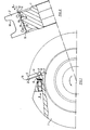
- the milling cutter partially shown in FIG. 1 essentially consists of a milling cutter body 1 and cutting inserts 2 which are inserted into corresponding grooves 3 formed on the milling cutter body 1. It can be, for example, three grooves arranged on the circumference of the milling cutter body 1 with associated cutting inserts. For the sake of simplicity, however, only one groove 3 with associated cutting 2 is shown in the drawing.
- the cutting 2 is located between two clamping elements, namely a clamping wedge 4 and a support plate 5, which together with the cutting 2 form a cassette. Centering pins 6 are provided so that the individual parts of the cassette do not slip against one another.
- the cuttings 2 are fastened to the cutter body 1 in such a way that the preassembled cassette is pushed into the groove 3 from above and pressed against the stop element 7 in accordance with the direction of arrow a (FIG. 2). In this position, the cassette is clamped in the groove 3 by means of a clamping screw 8.
- the clamping screw 8 is screwed into the milling cutter body 1 in the direction of arrow b, so that it is clamped with the clamping wedge 4.
- the cutting 2 has a recess 10 on its lower side 9, a lateral boundary 11 of which forms an axially acting bearing element 12.
- the lateral boundary 13 of the recess 10 opposite the bearing element 12 runs in an arc shape and forms an obtuse angle with the lower side 9 would be inserted with the curved lateral limit 13 against the stop element 7.
- the curved or curved boundary 13 can not serve as a stop or bearing, which is why the cassette with the cutting 2 would be pushed over the stop element 7. A reverse assembly of the cutting 2 is excluded in this way.
- the cutting 2 has two molded bearing cams 14 on the outside on the lower side 9, which rest on a flat bearing surface 15.
- the bearing surface 15 forms the groove base of the groove 3.
- the cutting 2 shown in FIGS. 1 and 2 has a U-shaped cutting edge 16, which is used, for example, for milling wooden profile strips.
- the radially acting bearing cams 14 are formed in a circular arc, so that a linear support is obtained.
- a point-like support can also be obtained by arching the support surface 15 or by using spherical bearing cams 14.
- the support surface 15 can be ground flat and the bearing cams 14 can be cylindrical.
- the axial bearing element 12 is shown as a straight stop, but this bearing element 12 is also preferably designed as a bearing cam.
- the right bearing cam 14 is designed as a radially acting bearing element and as an axial bearing element.
- an axially acting bearing cam 19 is provided, which has a different radius than the radially acting bearing cams 14.
- the axially acting Bearing cam 19 opposite side of the recess 10 is formed as a slope 20 in this embodiment.
- the arched boundaries 13 and the bevel 20 of FIG. 4 shown in FIGS. 2 and 3 each form an obtuse angle with the lower side 9 which is so large that these lateral boundaries of the cutouts 10 do not act as a stop for the stop element 7 can work.
- the axially acting bearing elements 12, 19 are arranged at a distance from the center 2l of the cutting inserts 2, 17, 19, which also prevents the inserting of the cutting inserts from reversing.
- bearing elements which are preferably designed as bearing cams, can also be formed in any other form.
Landscapes
- Engineering & Computer Science (AREA)
- Mechanical Engineering (AREA)
- Milling Processes (AREA)
Applications Claiming Priority (2)
| Application Number | Priority Date | Filing Date | Title |
|---|---|---|---|
| DE19848427007U DE8427007U1 (de) | 1984-09-13 | 1984-09-13 | Fraeser mit auswechselbaren schneidlingen |
| DE8427007U | 1984-09-13 |
Publications (2)
| Publication Number | Publication Date |
|---|---|
| EP0177700A1 true EP0177700A1 (fr) | 1986-04-16 |
| EP0177700B1 EP0177700B1 (fr) | 1989-07-19 |
Family
ID=6770667
Family Applications (1)
| Application Number | Title | Priority Date | Filing Date |
|---|---|---|---|
| EP85109737A Expired EP0177700B1 (fr) | 1984-09-13 | 1985-08-02 | Fraise à queue munie de plaquettes |
Country Status (3)
| Country | Link |
|---|---|
| US (1) | US4652182A (fr) |
| EP (1) | EP0177700B1 (fr) |
| DE (1) | DE8427007U1 (fr) |
Cited By (1)
| Publication number | Priority date | Publication date | Assignee | Title |
|---|---|---|---|---|
| EP0566858A1 (fr) * | 1992-04-18 | 1993-10-27 | UNITED HARDMETAL GmbH | Plaquette de coupe pour outil d'enlèvement de copeaux |
Families Citing this family (3)
| Publication number | Priority date | Publication date | Assignee | Title |
|---|---|---|---|---|
| DE20302868U1 (de) | 2003-02-21 | 2003-06-05 | Tigra Hartstoff GmbH, 86698 Oberndorf | Positionierungsvorrichtung für Schneidplatten in Messerköpfen |
| US7708040B2 (en) * | 2004-03-16 | 2010-05-04 | Key Knife, Inc. | High speed planer head |
| AU2023366705A1 (en) | 2022-10-29 | 2025-05-29 | Navarro RAMON | Cutter assembly |
Citations (4)
| Publication number | Priority date | Publication date | Assignee | Title |
|---|---|---|---|---|
| DE1143082B (de) * | 1960-06-03 | 1963-01-31 | Montanwerke Walter A G | Spanneinrichtung zum Klemmen von Schneidplatten in keilfoermigen Ausschnitten des Fraesergrundkoerpers |
| GB1241950A (en) * | 1967-08-24 | 1971-08-04 | Donald William Allen | Milling cutter |
| EP0049796A1 (fr) * | 1980-10-09 | 1982-04-21 | Stellram S.A. | Outil pour usinage à cartouches porte-plaquettes interchangeables |
| DE3319642A1 (de) * | 1983-05-31 | 1984-12-06 | Duropal-Werk Eberh. Wrede GmbH & Co KG, 5760 Arnsberg | Werkzeugtraeger, insbesondere fuer eine spanende bearbeitung von werkstuecken |
Family Cites Families (4)
| Publication number | Priority date | Publication date | Assignee | Title |
|---|---|---|---|---|
| US1194865A (en) * | 1916-08-15 | muller | ||
| US1962163A (en) * | 1931-04-30 | 1934-06-12 | O K Tool Co Inc | Cutter blade lock |
| US3217384A (en) * | 1962-02-26 | 1965-11-16 | Sandvikens Jernverks Ab | Milling cutter |
| GB1316637A (en) * | 1970-06-09 | 1973-05-09 | Wadkin Ltd | Rotary cutter for woodworking and similar machines |
-
1984
- 1984-09-13 DE DE19848427007U patent/DE8427007U1/de not_active Expired
-
1985
- 1985-08-02 EP EP85109737A patent/EP0177700B1/fr not_active Expired
- 1985-09-11 US US06/774,670 patent/US4652182A/en not_active Expired - Lifetime
Patent Citations (4)
| Publication number | Priority date | Publication date | Assignee | Title |
|---|---|---|---|---|
| DE1143082B (de) * | 1960-06-03 | 1963-01-31 | Montanwerke Walter A G | Spanneinrichtung zum Klemmen von Schneidplatten in keilfoermigen Ausschnitten des Fraesergrundkoerpers |
| GB1241950A (en) * | 1967-08-24 | 1971-08-04 | Donald William Allen | Milling cutter |
| EP0049796A1 (fr) * | 1980-10-09 | 1982-04-21 | Stellram S.A. | Outil pour usinage à cartouches porte-plaquettes interchangeables |
| DE3319642A1 (de) * | 1983-05-31 | 1984-12-06 | Duropal-Werk Eberh. Wrede GmbH & Co KG, 5760 Arnsberg | Werkzeugtraeger, insbesondere fuer eine spanende bearbeitung von werkstuecken |
Cited By (1)
| Publication number | Priority date | Publication date | Assignee | Title |
|---|---|---|---|---|
| EP0566858A1 (fr) * | 1992-04-18 | 1993-10-27 | UNITED HARDMETAL GmbH | Plaquette de coupe pour outil d'enlèvement de copeaux |
Also Published As
| Publication number | Publication date |
|---|---|
| EP0177700B1 (fr) | 1989-07-19 |
| DE8427007U1 (de) | 1984-12-13 |
| US4652182A (en) | 1987-03-24 |
Similar Documents
| Publication | Publication Date | Title |
|---|---|---|
| EP0084607B1 (fr) | Outil de fraisage | |
| DE2161233A1 (de) | Scheibenfräser, insbesondere Schlitz-, Nut- oder Formfräser | |
| CH616611A5 (fr) | ||
| DE2848554C2 (de) | Stanzwerkzeug | |
| DE112008000835B4 (de) | Plattenelement, rotierendes Werkzeug, das das Plattenelement verwendet, und Schneidverfahren, das das rotierende Werkzeug verwendet | |
| DE4118070C2 (de) | Werkzeug für die spanende Bearbeitung | |
| DE2065306A1 (de) | Bohrkopf | |
| EP0027174B1 (fr) | Outil de coupe | |
| DE3311467C2 (fr) | ||
| EP0357549A1 (fr) | Couteaux rotatifs | |
| DE2736612A1 (de) | Wendeplatten-messerkopf | |
| DE3140905C2 (de) | Planfräsmesserkopf | |
| EP1033210B1 (fr) | Plaquette de coupe, en particulier pour un outil de fraisage | |
| DE3610256C2 (fr) | ||
| DE102016217533A1 (de) | Fräser für RN-Wendeschneidplatten mit Indexierung (definierte Weitertaktung der Schneidplatte) | |
| EP0177700B1 (fr) | Fraise à queue munie de plaquettes | |
| DE3013876A1 (de) | Spanabhebendes werkzeug | |
| DE2526345A1 (de) | Scheibenfraeser | |
| DE2718787A1 (de) | Schneidwerkzeug | |
| EP0355305A2 (fr) | Fraise disque | |
| DE9414327U1 (de) | Messerplattenhalterung für Messerköpfe | |
| DE3828482C2 (de) | Stoss- oder Ziehwerkzeug | |
| EP0085040A2 (fr) | Broche d'outil pour la fabrication de capeaux plat en bois | |
| DE2726734C2 (de) | Einstechwerkzeug und Verfahren zum Fertigbearbeiten eines solchen Einstechwerkzeugs | |
| DE19600924C1 (de) | Fräskopf |
Legal Events
| Date | Code | Title | Description |
|---|---|---|---|
| PUAI | Public reference made under article 153(3) epc to a published international application that has entered the european phase |
Free format text: ORIGINAL CODE: 0009012 |
|
| AK | Designated contracting states |
Kind code of ref document: A1 Designated state(s): CH FR GB IT LI |
|
| 17P | Request for examination filed |
Effective date: 19860307 |
|
| 17Q | First examination report despatched |
Effective date: 19870624 |
|
| GRAA | (expected) grant |
Free format text: ORIGINAL CODE: 0009210 |
|
| AK | Designated contracting states |
Kind code of ref document: B1 Designated state(s): CH FR GB IT LI |
|
| ET | Fr: translation filed | ||
| ITF | It: translation for a ep patent filed | ||
| GBT | Gb: translation of ep patent filed (gb section 77(6)(a)/1977) | ||
| PLBE | No opposition filed within time limit |
Free format text: ORIGINAL CODE: 0009261 |
|
| STAA | Information on the status of an ep patent application or granted ep patent |
Free format text: STATUS: NO OPPOSITION FILED WITHIN TIME LIMIT |
|
| 26N | No opposition filed | ||
| ITTA | It: last paid annual fee | ||
| PGFP | Annual fee paid to national office [announced via postgrant information from national office to epo] |
Ref country code: FR Payment date: 19980709 Year of fee payment: 14 |
|
| PGFP | Annual fee paid to national office [announced via postgrant information from national office to epo] |
Ref country code: GB Payment date: 19980724 Year of fee payment: 14 |
|
| PGFP | Annual fee paid to national office [announced via postgrant information from national office to epo] |
Ref country code: CH Payment date: 19980907 Year of fee payment: 14 |
|
| PG25 | Lapsed in a contracting state [announced via postgrant information from national office to epo] |
Ref country code: GB Free format text: LAPSE BECAUSE OF NON-PAYMENT OF DUE FEES Effective date: 19990802 |
|
| PG25 | Lapsed in a contracting state [announced via postgrant information from national office to epo] |
Ref country code: LI Free format text: LAPSE BECAUSE OF NON-PAYMENT OF DUE FEES Effective date: 19990831 Ref country code: CH Free format text: LAPSE BECAUSE OF NON-PAYMENT OF DUE FEES Effective date: 19990831 |
|
| GBPC | Gb: european patent ceased through non-payment of renewal fee |
Effective date: 19990802 |
|
| REG | Reference to a national code |
Ref country code: CH Ref legal event code: PL |
|
| PG25 | Lapsed in a contracting state [announced via postgrant information from national office to epo] |
Ref country code: FR Free format text: LAPSE BECAUSE OF NON-PAYMENT OF DUE FEES Effective date: 20000428 |
|
| REG | Reference to a national code |
Ref country code: FR Ref legal event code: ST |