EP0177706A1 - Serrure contenant au moins un aimant tournant - Google Patents
Serrure contenant au moins un aimant tournant Download PDFInfo
- Publication number
- EP0177706A1 EP0177706A1 EP85109972A EP85109972A EP0177706A1 EP 0177706 A1 EP0177706 A1 EP 0177706A1 EP 85109972 A EP85109972 A EP 85109972A EP 85109972 A EP85109972 A EP 85109972A EP 0177706 A1 EP0177706 A1 EP 0177706A1
- Authority
- EP
- European Patent Office
- Prior art keywords
- rotor
- bearing
- magnet
- magnetic
- lock
- Prior art date
- Legal status (The legal status is an assumption and is not a legal conclusion. Google has not performed a legal analysis and makes no representation as to the accuracy of the status listed.)
- Granted
Links
- 238000006073 displacement reaction Methods 0.000 claims abstract description 6
- 230000010355 oscillation Effects 0.000 description 4
- 230000000903 blocking effect Effects 0.000 description 1
- 244000309466 calf Species 0.000 description 1
- 230000000694 effects Effects 0.000 description 1
- 230000002093 peripheral effect Effects 0.000 description 1
Images

Classifications
-
- E—FIXED CONSTRUCTIONS
- E05—LOCKS; KEYS; WINDOW OR DOOR FITTINGS; SAFES
- E05B—LOCKS; ACCESSORIES THEREFOR; HANDCUFFS
- E05B47/00—Operating or controlling locks or other fastening devices by electric or magnetic means
- E05B47/0038—Operating or controlling locks or other fastening devices by electric or magnetic means using permanent magnets
- E05B47/0042—Operating or controlling locks or other fastening devices by electric or magnetic means using permanent magnets with rotary magnet tumblers
-
- Y—GENERAL TAGGING OF NEW TECHNOLOGICAL DEVELOPMENTS; GENERAL TAGGING OF CROSS-SECTIONAL TECHNOLOGIES SPANNING OVER SEVERAL SECTIONS OF THE IPC; TECHNICAL SUBJECTS COVERED BY FORMER USPC CROSS-REFERENCE ART COLLECTIONS [XRACs] AND DIGESTS
- Y10—TECHNICAL SUBJECTS COVERED BY FORMER USPC
- Y10T—TECHNICAL SUBJECTS COVERED BY FORMER US CLASSIFICATION
- Y10T70/00—Locks
- Y10T70/70—Operating mechanism
- Y10T70/7051—Using a powered device [e.g., motor]
- Y10T70/7057—Permanent magnet
-
- Y—GENERAL TAGGING OF NEW TECHNOLOGICAL DEVELOPMENTS; GENERAL TAGGING OF CROSS-SECTIONAL TECHNOLOGIES SPANNING OVER SEVERAL SECTIONS OF THE IPC; TECHNICAL SUBJECTS COVERED BY FORMER USPC CROSS-REFERENCE ART COLLECTIONS [XRACs] AND DIGESTS
- Y10—TECHNICAL SUBJECTS COVERED BY FORMER USPC
- Y10T—TECHNICAL SUBJECTS COVERED BY FORMER US CLASSIFICATION
- Y10T70/00—Locks
- Y10T70/70—Operating mechanism
- Y10T70/7441—Key
- Y10T70/7486—Single key
- Y10T70/7508—Tumbler type
- Y10T70/7559—Cylinder type
- Y10T70/7588—Rotary plug
- Y10T70/7627—Rotary or swinging tumblers
-
- Y—GENERAL TAGGING OF NEW TECHNOLOGICAL DEVELOPMENTS; GENERAL TAGGING OF CROSS-SECTIONAL TECHNOLOGIES SPANNING OVER SEVERAL SECTIONS OF THE IPC; TECHNICAL SUBJECTS COVERED BY FORMER USPC CROSS-REFERENCE ART COLLECTIONS [XRACs] AND DIGESTS
- Y10—TECHNICAL SUBJECTS COVERED BY FORMER USPC
- Y10T—TECHNICAL SUBJECTS COVERED BY FORMER US CLASSIFICATION
- Y10T70/00—Locks
- Y10T70/70—Operating mechanism
- Y10T70/7441—Key
- Y10T70/778—Operating elements
- Y10T70/7791—Keys
- Y10T70/7904—Magnetic features
Definitions
- the invention relates to a lock with at least one magnetic rotor, the rotational position of which can be adjusted by a key magnet in accordance with the selected magnetic coding and can be scanned by a scanning element of the lock.
- Such locks are known and detailed e.g. in AT-PSs 341 901 and 357 430.
- the essential features of these and similar locks are the magnetic rotors, the rotational position of which can be adjusted according to the magnetic coding by means of associated key magnets, the correct rotational position being able to be sensed by scanning elements of the lock.
- the scanning element can be inserted into a recess in the magnetic rotor and the displacement movement in turn controls a locking element which effects the locking of the lock or permits the lock to be rotated.
- Such locks can e.g. Be cylinder locks or sliding locks.
- the object is achieved in that the magnet rotor is mounted so as to be displaceable in the direction of its axis, and in that the scanning element is set up for scanning the magnet rotor in a predetermined displacement position of the magnet rotor. Furthermore, according to the invention, the displaceability of the magnetic rotor is limited by counter bearings on which the associated bearing of the magnetic rotor comes to rest, and this is between 10 and 80% of the length of the axis of the magnetic rotor. Furthermore, the invention is characterized in that the bearing of the magnetic rotor facing the key magnet has a larger bearing has friction than the other bearing, that the bearing facing the key magnet is planar and the other bearing is designed for point storage and that the bearing is annular.
- the extension a of the scanning element is greater than the distance b from the bearing to the peripheral abutting edge of the magnet rotor and smaller than the distance b + c of the extension from the bearing to the abutting edge when the magnet rotor is in the released position.
- the magnetic rotor has a sensing disk which is arranged at a distance from the magnetic body and which is provided with one or more recesses for scanning by the sensing element, and in that the magnetic body is surrounded by an enclosure which is separate from the sensing disk and which forms a Has abutting edge, the outer diameter of which has at least the diameter of the sensing disc.
- Fig. 1 is used schematically to explain the problem underlying the invention.
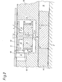
- Fig. 2 is a cross section through part of a lock according to the invention, the section being arranged in the plane of the axis of the magnet rotor.
- Fig. 1 shows schematically the magnetic rotor 1 of the magnetic lock and the key 11 in a position before it is inserted so far into the lock that the key magnet 2 comes to lie congruently over the magnetic rotor 1.
- the magnet rotor 1 can be freely rotated about the axis 12 and has the two magnetic poles S-N, the magnetic dividing line 13 running approximately radially here.
- the magnetic rotor has a recess 9, the rotational position of which can be scanned by means of a scanning element 8 shown further below in FIG. 2, which is only indicated schematically here.
- the key 11 is a wrong key, because it should turn the magnet rotor 1 into the blocking position with its key magnet 2 (rotated by 180 ° to the position shown), so that the scanning element 8 cannot snap into the recess 9, but on the i surface of the Rotors abuts. Nevertheless, it can happen that the wrong key 11 locks the lock: the magnet rotor 1 has the marked release position, which is predetermined, for example, by the fact that the Key magnet 22, which is assigned to a further magnet rotor of the lock, brings the magnet rotor 1 into this position as it slides past.
- the alignment of the magnetic fields of the key magnet 2 and of the magnet rotor 1 does not then result in a torque which rotates the magnet rotor by 180 °, but merely repulsive forces occur between the superposed N and S poles.
- the scanning element 8 can thus continue to enter the recess 9 and the lock can be operated despite the wrong key.
- a locking cylinder is shown, in the core 14 of which the magnet rotor 1 is arranged in a core recess 3.
- the key channel 15 is provided, into which the key 11 is inserted such that the key magnet 2 is opposite the magnet rotor 1.
- the core recess 3 is closed off from the key channel by the wall 16 and at the top by a scanning slide 17.
- the scanning slide 17 is displaceable in the direction of the arrow 18 and carries the scanning element 8, which can enter the recess 9 when the magnetic rotor 1 is in the correct position.
- the magnet rotor is freed from mass as far as possible and consists of the magnetic body 19, the sensing disk 20, which has one or more rotor recesses 9. Furthermore, a surround 21 is arranged around the magnetic body 19, which protects the magnetic body 19 and through which a butt edge 10 is formed.
- the magnet rotor can be pushed up and down in the axial direction by the distance c. If there is a 180 ° incorrect position of the magnetic rotor, so that the magnetic rotor assumes the position according to FIG. 1 with respect to the key magnet, then the repulsive forces between the southern and northern poles cause the magnetic rotor to be lifted into the position shown in FIG. 2. As a result, the pointed bearing 7, which is provided with low frictional forces, comes into contact with the counter-bearing S. The thrusting chew 10 is so small from the counter-bearing 5 that the scanning element 8 cannot enter the recess 9 but hang on the abutting edge 10 remains. This enables the magnet rotor 1 to rotate after a short time into the correct position rotated by 180 °, which is an extremely short period of time.
- the bearing 6 is preferably ring-shaped, the diameter of the ring determining the frictional forces. The larger the diameter of the bearing 6, the more the oscillation is suppressed.
- the magnetic rotor is constructed in a particularly advantageous manner with a very low mass.
- the most mass-bearing element is the magnetic body 19, which is attached to the axis 12.
- the axis 12 is formed in one piece with the touch disk 20.
- the enclosure 21 serves to protect the magnetic body 19 and is U-shaped in cross section in FIG. 2.
- the lower leg of the U can also be omitted, since only the upper leg forms the abutting edge 10 here.
- the displacement is in a preferred manner 10 to 80%, in particular 30 to 40% of the length y of the axis 12.
- the arrangement of the magnet rotor with the displacement c is in no way restricted l ction to the illustrated embodiment, the remaining Magnetschiquekonstn.
- the counter bearings 4, 5 are simply formed in the present exemplary embodiment by the calf 16 and the scanning slide 17. Structurally specially designed bearing points can also be provided.
Landscapes
- Lock And Its Accessories (AREA)
- Measurement Of Length, Angles, Or The Like Using Electric Or Magnetic Means (AREA)
Applications Claiming Priority (2)
| Application Number | Priority Date | Filing Date | Title |
|---|---|---|---|
| AT3214/84 | 1984-10-09 | ||
| AT0321484A AT385311B (de) | 1984-10-09 | 1984-10-09 | Schloss mit zumindest einem magnetrotor |
Publications (2)
| Publication Number | Publication Date |
|---|---|
| EP0177706A1 true EP0177706A1 (fr) | 1986-04-16 |
| EP0177706B1 EP0177706B1 (fr) | 1989-03-15 |
Family
ID=3547125
Family Applications (1)
| Application Number | Title | Priority Date | Filing Date |
|---|---|---|---|
| EP85109972A Expired EP0177706B1 (fr) | 1984-10-09 | 1985-08-08 | Serrure contenant au moins un aimant tournant |
Country Status (6)
| Country | Link |
|---|---|
| US (1) | US4686841A (fr) |
| EP (1) | EP0177706B1 (fr) |
| AT (1) | AT385311B (fr) |
| CA (1) | CA1246888A (fr) |
| DD (1) | DD236961A5 (fr) |
| DE (1) | DE3568816D1 (fr) |
Cited By (2)
| Publication number | Priority date | Publication date | Assignee | Title |
|---|---|---|---|---|
| CN102409906A (zh) * | 2011-08-03 | 2012-04-11 | 深圳市中联创新自控系统有限公司 | 电锁断电自动开锁装置及带有该装置的电锁 |
| ITMI20111725A1 (it) * | 2011-09-26 | 2013-03-27 | Leonardo Chiarion | Dispositivo di accoppiamento magnetico. |
Families Citing this family (18)
| Publication number | Priority date | Publication date | Assignee | Title |
|---|---|---|---|---|
| DE3742826A1 (de) * | 1987-08-22 | 1989-03-02 | Schulte Schlagbaum Ag | Aus schloss und mehreren schluesseln bestehendes schliesssystem |
| US5485733A (en) * | 1993-05-13 | 1996-01-23 | Hoffman; Charles G. | Concealed magnetic lock for cabinet closure |
| JP4336657B2 (ja) * | 2003-02-17 | 2009-09-30 | コンセプツ エ イノバション ゾン セキュリテ マグネティーク | 磁気制御式施錠デバイス |
| DE10312269A1 (de) * | 2003-03-19 | 2004-09-30 | Drumm Gmbh | Magneto-mechanische Schließeinrichtung |
| US7567159B2 (en) * | 2005-02-03 | 2009-07-28 | Macken John A | Energy absorbing magnetic coupling device |
| US20070039141A1 (en) * | 2005-08-22 | 2007-02-22 | Rairden Kenneth D | Rotating magnetic fastener |
| AU2010101261B4 (en) * | 2010-07-23 | 2011-02-03 | Australian Sciences | Magnetic Connection System |
| US8641105B2 (en) * | 2011-01-25 | 2014-02-04 | Won-Door Corporation | Securing mechanisms for partitions, partition systems including same, and related methods |
| US9447619B2 (en) * | 2012-08-14 | 2016-09-20 | Amazon Technologies, Inc. | 90 degree magnetic latch to prevent high surface flux |
| US10422161B2 (en) | 2015-05-20 | 2019-09-24 | Hamish Connan | Magnetic lock mechanism |
| WO2017201190A1 (fr) * | 2016-05-18 | 2017-11-23 | Shanghai Yanfeng Jinqiao Automotive Trim Systems Co. Ltd | Ensemble console pour intérieur de véhicule |
| US10662686B2 (en) | 2016-09-30 | 2020-05-26 | Barrette Outdoor Living, Inc. | Magnetic safety gate latch |
| US10855158B2 (en) * | 2018-04-19 | 2020-12-01 | Watasensor, Inc. | Magnetic power generation |
| DE102019100637A1 (de) * | 2019-01-11 | 2020-07-16 | Simonswerk Gmbh | Magnetschloss sowie Tür |
| US11572723B2 (en) | 2019-02-27 | 2023-02-07 | Shanghai Yanfeng Jinqiao Automotive Triim Systems Co. Ltd. | Vehicle interior component |
| IL266258B2 (en) * | 2019-04-28 | 2024-06-01 | Mul T Lock Technologies Ltd | Rotating magnetic key attachment element |
| US11230859B2 (en) | 2019-07-05 | 2022-01-25 | Daniel Petersen | Magnetic keyed lock |
| US12258786B2 (en) * | 2020-08-20 | 2025-03-25 | Cameron Neil Carr | Magnetic privacy lock control |
Citations (3)
| Publication number | Priority date | Publication date | Assignee | Title |
|---|---|---|---|---|
| DE2504774A1 (de) * | 1974-02-13 | 1975-08-14 | Engineering Design And Dev Pty | Schloss |
| AT341901B (de) * | 1975-07-03 | 1978-03-10 | Evva Werke | Steuereinrichtung, insbesondere schloss |
| AT357430B (de) * | 1978-06-29 | 1980-07-10 | Evva Werke | Steuereinrichtung, insbesondere schloss |
Family Cites Families (11)
| Publication number | Priority date | Publication date | Assignee | Title |
|---|---|---|---|---|
| US3570287A (en) * | 1965-07-31 | 1971-03-16 | Huwil Werke Gmbh | Magnetic lock with rotatable latching element |
| SE325490B (fr) * | 1966-06-25 | 1970-06-29 | G Heimann | |
| JPS4810839B1 (fr) * | 1967-10-19 | 1973-04-07 | ||
| US3855827A (en) * | 1973-04-26 | 1974-12-24 | Mrt Magnet Regeltechnik Gmbh | Magnetically-operated locking mechanisms |
| SE395500B (sv) * | 1973-10-25 | 1977-08-15 | Boving Egon | Av en permanentmagnetnyckel paverkbart vridcylinderlas |
| DE2515161C3 (de) * | 1975-04-08 | 1979-05-17 | Waldemar H. 4000 Duesseldorf Kurpanek | Steuerbarer, in der Offen- bzw. Schließlage durch Dauermagnete gehaltener Schubriegel eines Schlosses |
| US4333327A (en) * | 1977-03-25 | 1982-06-08 | Miwa Lock Co., Ltd. | Magnetic tumbler lock |
| AT352567B (de) * | 1978-02-09 | 1979-09-25 | Evva Werke | Steuereinrichtung |
| DE7904280U1 (de) * | 1978-03-06 | 1984-01-19 | Evva-Werk Spezialerzeugung von Zylinder- und Sicherheitsschlössern GmbH & Co KG, 1120 Wien | Steuereinrichtung, insbesondere schloss |
| DE2833453A1 (de) * | 1978-07-29 | 1980-02-07 | Ymos Metallwerke Wolf & Becker | Magnetschloss |
| US4516416A (en) * | 1980-02-08 | 1985-05-14 | Evva-Werk Spezialerzeugung Von Zylinder- Und Sicherheitsschlossern Gesellschaft M.B.H. & Co. Kommanditgesellschaft | Locking device and key |
-
1984
- 1984-10-09 AT AT0321484A patent/AT385311B/de not_active IP Right Cessation
-
1985
- 1985-08-08 EP EP85109972A patent/EP0177706B1/fr not_active Expired
- 1985-08-08 DE DE8585109972T patent/DE3568816D1/de not_active Expired
- 1985-10-01 DD DD85281256A patent/DD236961A5/de unknown
- 1985-10-07 US US06/785,558 patent/US4686841A/en not_active Expired - Fee Related
- 1985-10-08 CA CA000492508A patent/CA1246888A/fr not_active Expired
Patent Citations (3)
| Publication number | Priority date | Publication date | Assignee | Title |
|---|---|---|---|---|
| DE2504774A1 (de) * | 1974-02-13 | 1975-08-14 | Engineering Design And Dev Pty | Schloss |
| AT341901B (de) * | 1975-07-03 | 1978-03-10 | Evva Werke | Steuereinrichtung, insbesondere schloss |
| AT357430B (de) * | 1978-06-29 | 1980-07-10 | Evva Werke | Steuereinrichtung, insbesondere schloss |
Cited By (4)
| Publication number | Priority date | Publication date | Assignee | Title |
|---|---|---|---|---|
| CN102409906A (zh) * | 2011-08-03 | 2012-04-11 | 深圳市中联创新自控系统有限公司 | 电锁断电自动开锁装置及带有该装置的电锁 |
| CN102409906B (zh) * | 2011-08-03 | 2014-02-26 | 深圳市中联创新自控系统有限公司 | 电锁断电自动开锁装置及带有该装置的电锁 |
| ITMI20111725A1 (it) * | 2011-09-26 | 2013-03-27 | Leonardo Chiarion | Dispositivo di accoppiamento magnetico. |
| WO2013045390A1 (fr) * | 2011-09-26 | 2013-04-04 | Zamengo, Giovanni | Fermeture à glissière magnétique |
Also Published As
| Publication number | Publication date |
|---|---|
| ATA321484A (de) | 1987-08-15 |
| US4686841A (en) | 1987-08-18 |
| DE3568816D1 (en) | 1989-04-20 |
| CA1246888A (fr) | 1988-12-20 |
| EP0177706B1 (fr) | 1989-03-15 |
| DD236961A5 (de) | 1986-06-25 |
| AT385311B (de) | 1988-03-25 |
Similar Documents
| Publication | Publication Date | Title |
|---|---|---|
| EP0177706B1 (fr) | Serrure contenant au moins un aimant tournant | |
| DE3234405C3 (de) | Anordnung zum drehsicherung eines einstellrings einer taucheruhr | |
| DE102013202157A1 (de) | Kombinationsvorhängeschloss mit Scheibenform | |
| DE2161845A1 (de) | Einbauring für Wälzlager zur wahlweisen Verwendung als Dichtung und als Abdeckung | |
| DE2338795A1 (de) | Sicherheitsschloss | |
| EP1132934A1 (fr) | Interrupteur rotatif | |
| DE1760972B2 (de) | Elektromagnetisch gesteuerte mustervorrichtung fuer rundstrickmaschinen | |
| DE2850744C2 (fr) | ||
| DE2517689A1 (de) | Mechanisches schloss | |
| DE2423573C3 (de) | Magnetisch betätigbare Steuervorrichtung | |
| EP0095572A1 (fr) | Dispositif de blocage du sens de rotation du rotor d'un moteur synchrone | |
| DE3608275A1 (de) | Geraet zum lesen einer datenspur einer karte | |
| DE4337589C2 (de) | Gleichstrom-Hubmagnet | |
| DE4216421A1 (de) | Aus Schloß und mehreren Schlüsseln bestehendes Schließsystem | |
| EP0182976A2 (fr) | Serrure cylindrique avec un boîtier dans lequel pivote un noyau portant une ou plusieurs gorges, en particulier gorges à rotor magnétique | |
| DE102016122174B4 (de) | Einstellvorrichtung | |
| DE1774529A1 (de) | Plattenspeicher fuer Maschinen zum Sortieren von Aufzeichnungskarten | |
| DE2154637C3 (de) | Drehmagnet | |
| DE1428535C3 (de) | Permutationsschloß mit Einstellfühler | |
| DE1638469C3 (de) | Selbstanlaufender Synchronmotor | |
| DE69426015T2 (de) | Gegen unbefugte Entriegelung gesicherte Zylinderschlossvorrichtung | |
| DE2403565A1 (de) | Ruecksprungrastwerk | |
| DE1298911B (de) | Kugelschreiber | |
| DE3023212A1 (de) | Schliesszylinder | |
| DE2236744C3 (de) | DrehspulmeBwerk mit einem Weicheisenkern |
Legal Events
| Date | Code | Title | Description |
|---|---|---|---|
| PUAI | Public reference made under article 153(3) epc to a published international application that has entered the european phase |
Free format text: ORIGINAL CODE: 0009012 |
|
| 17P | Request for examination filed |
Effective date: 19860108 |
|
| AK | Designated contracting states |
Kind code of ref document: A1 Designated state(s): CH DE FR GB IT LI NL SE |
|
| 17Q | First examination report despatched |
Effective date: 19871020 |
|
| GRAA | (expected) grant |
Free format text: ORIGINAL CODE: 0009210 |
|
| AK | Designated contracting states |
Kind code of ref document: B1 Designated state(s): CH DE FR GB IT LI NL SE |
|
| PG25 | Lapsed in a contracting state [announced via postgrant information from national office to epo] |
Ref country code: SE Effective date: 19890315 Ref country code: NL Effective date: 19890315 Ref country code: IT Free format text: LAPSE BECAUSE OF FAILURE TO SUBMIT A TRANSLATION OF THE DESCRIPTION OR TO PAY THE FEE WITHIN THE PRESCRIBED TIME-LIMIT;WARNING: LAPSES OF ITALIAN PATENTS WITH EFFECTIVE DATE BEFORE 2007 MAY HAVE OCCURRED AT ANY TIME BEFORE 2007. THE CORRECT EFFECTIVE DATE MAY BE DIFFERENT FROM THE ONE RECORDED. Effective date: 19890315 Ref country code: GB Free format text: LAPSE BECAUSE OF NON-PAYMENT OF DUE FEES Effective date: 19890315 Ref country code: FR Free format text: THE PATENT HAS BEEN ANNULLED BY A DECISION OF A NATIONAL AUTHORITY Effective date: 19890315 |
|
| REF | Corresponds to: |
Ref document number: 3568816 Country of ref document: DE Date of ref document: 19890420 |
|
| EN | Fr: translation not filed | ||
| NLV1 | Nl: lapsed or annulled due to failure to fulfill the requirements of art. 29p and 29m of the patents act | ||
| PG25 | Lapsed in a contracting state [announced via postgrant information from national office to epo] |
Ref country code: LI Effective date: 19890831 Ref country code: CH Effective date: 19890831 |
|
| GBV | Gb: ep patent (uk) treated as always having been void in accordance with gb section 77(7)/1977 [no translation filed] | ||
| PLBE | No opposition filed within time limit |
Free format text: ORIGINAL CODE: 0009261 |
|
| STAA | Information on the status of an ep patent application or granted ep patent |
Free format text: STATUS: NO OPPOSITION FILED WITHIN TIME LIMIT |
|
| 26N | No opposition filed | ||
| REG | Reference to a national code |
Ref country code: CH Ref legal event code: PL |
|
| PG25 | Lapsed in a contracting state [announced via postgrant information from national office to epo] |
Ref country code: DE Effective date: 19900501 |