EP0177718A2 - Verfahren und Vorrichtung zur Sortierung von mikroskopischen Partikeln - Google Patents
Verfahren und Vorrichtung zur Sortierung von mikroskopischen Partikeln Download PDFInfo
- Publication number
- EP0177718A2 EP0177718A2 EP85110397A EP85110397A EP0177718A2 EP 0177718 A2 EP0177718 A2 EP 0177718A2 EP 85110397 A EP85110397 A EP 85110397A EP 85110397 A EP85110397 A EP 85110397A EP 0177718 A2 EP0177718 A2 EP 0177718A2
- Authority
- EP
- European Patent Office
- Prior art keywords
- channel
- sorting
- pressure wave
- particle
- measuring
- Prior art date
- Legal status (The legal status is an assumption and is not a legal conclusion. Google has not performed a legal analysis and makes no representation as to the accuracy of the status listed.)
- Granted
Links
Images




Classifications
-
- G—PHYSICS
- G01—MEASURING; TESTING
- G01N—INVESTIGATING OR ANALYSING MATERIALS BY DETERMINING THEIR CHEMICAL OR PHYSICAL PROPERTIES
- G01N15/00—Investigating characteristics of particles; Investigating permeability, pore-volume or surface-area of porous materials
- G01N15/10—Investigating individual particles
- G01N15/14—Optical investigation techniques, e.g. flow cytometry
- G01N15/1404—Handling flow, e.g. hydrodynamic focusing
-
- B—PERFORMING OPERATIONS; TRANSPORTING
- B01—PHYSICAL OR CHEMICAL PROCESSES OR APPARATUS IN GENERAL
- B01L—CHEMICAL OR PHYSICAL LABORATORY APPARATUS FOR GENERAL USE
- B01L3/00—Containers or dishes for laboratory use, e.g. laboratory glassware; Droppers
- B01L3/50—Containers for the purpose of retaining a material to be analysed, e.g. test tubes
- B01L3/502—Containers for the purpose of retaining a material to be analysed, e.g. test tubes with fluid transport, e.g. in multi-compartment structures
- B01L3/5027—Containers for the purpose of retaining a material to be analysed, e.g. test tubes with fluid transport, e.g. in multi-compartment structures by integrated microfluidic structures, i.e. dimensions of channels and chambers are such that surface tension forces are important, e.g. lab-on-a-chip
- B01L3/502761—Containers for the purpose of retaining a material to be analysed, e.g. test tubes with fluid transport, e.g. in multi-compartment structures by integrated microfluidic structures, i.e. dimensions of channels and chambers are such that surface tension forces are important, e.g. lab-on-a-chip specially adapted for handling suspended solids or molecules independently from the bulk fluid flow, e.g. for trapping or sorting beads or physically stretching molecules
-
- B—PERFORMING OPERATIONS; TRANSPORTING
- B01—PHYSICAL OR CHEMICAL PROCESSES OR APPARATUS IN GENERAL
- B01L—CHEMICAL OR PHYSICAL LABORATORY APPARATUS FOR GENERAL USE
- B01L2200/00—Solutions for specific problems relating to chemical or physical laboratory apparatus
- B01L2200/06—Fluid handling related problems
- B01L2200/0647—Handling flowable solids, e.g. microscopic beads, cells, particles
- B01L2200/0652—Sorting or classification of particles or molecules
-
- B—PERFORMING OPERATIONS; TRANSPORTING
- B01—PHYSICAL OR CHEMICAL PROCESSES OR APPARATUS IN GENERAL
- B01L—CHEMICAL OR PHYSICAL LABORATORY APPARATUS FOR GENERAL USE
- B01L2400/00—Moving or stopping fluids
- B01L2400/04—Moving fluids with specific forces or mechanical means
- B01L2400/0403—Moving fluids with specific forces or mechanical means specific forces
- B01L2400/0433—Moving fluids with specific forces or mechanical means specific forces vibrational forces
- B01L2400/0439—Moving fluids with specific forces or mechanical means specific forces vibrational forces ultrasonic vibrations, vibrating piezo elements
-
- B—PERFORMING OPERATIONS; TRANSPORTING
- B01—PHYSICAL OR CHEMICAL PROCESSES OR APPARATUS IN GENERAL
- B01L—CHEMICAL OR PHYSICAL LABORATORY APPARATUS FOR GENERAL USE
- B01L2400/00—Moving or stopping fluids
- B01L2400/04—Moving fluids with specific forces or mechanical means
- B01L2400/0475—Moving fluids with specific forces or mechanical means specific mechanical means and fluid pressure
- B01L2400/0478—Moving fluids with specific forces or mechanical means specific mechanical means and fluid pressure pistons
-
- B—PERFORMING OPERATIONS; TRANSPORTING
- B01—PHYSICAL OR CHEMICAL PROCESSES OR APPARATUS IN GENERAL
- B01L—CHEMICAL OR PHYSICAL LABORATORY APPARATUS FOR GENERAL USE
- B01L2400/00—Moving or stopping fluids
- B01L2400/04—Moving fluids with specific forces or mechanical means
- B01L2400/0475—Moving fluids with specific forces or mechanical means specific mechanical means and fluid pressure
- B01L2400/0487—Moving fluids with specific forces or mechanical means specific mechanical means and fluid pressure fluid pressure, pneumatics
-
- G—PHYSICS
- G01—MEASURING; TESTING
- G01N—INVESTIGATING OR ANALYSING MATERIALS BY DETERMINING THEIR CHEMICAL OR PHYSICAL PROPERTIES
- G01N15/00—Investigating characteristics of particles; Investigating permeability, pore-volume or surface-area of porous materials
- G01N15/10—Investigating individual particles
- G01N15/14—Optical investigation techniques, e.g. flow cytometry
- G01N15/1484—Optical investigation techniques, e.g. flow cytometry microstructural devices
-
- G—PHYSICS
- G01—MEASURING; TESTING
- G01N—INVESTIGATING OR ANALYSING MATERIALS BY DETERMINING THEIR CHEMICAL OR PHYSICAL PROPERTIES
- G01N15/00—Investigating characteristics of particles; Investigating permeability, pore-volume or surface-area of porous materials
- G01N15/10—Investigating individual particles
- G01N15/14—Optical investigation techniques, e.g. flow cytometry
- G01N15/149—Optical investigation techniques, e.g. flow cytometry specially adapted for sorting particles, e.g. by their size or optical properties
-
- G—PHYSICS
- G01—MEASURING; TESTING
- G01N—INVESTIGATING OR ANALYSING MATERIALS BY DETERMINING THEIR CHEMICAL OR PHYSICAL PROPERTIES
- G01N15/00—Investigating characteristics of particles; Investigating permeability, pore-volume or surface-area of porous materials
- G01N15/10—Investigating individual particles
- G01N15/14—Optical investigation techniques, e.g. flow cytometry
- G01N15/1404—Handling flow, e.g. hydrodynamic focusing
- G01N2015/1415—Control of particle position
-
- Y—GENERAL TAGGING OF NEW TECHNOLOGICAL DEVELOPMENTS; GENERAL TAGGING OF CROSS-SECTIONAL TECHNOLOGIES SPANNING OVER SEVERAL SECTIONS OF THE IPC; TECHNICAL SUBJECTS COVERED BY FORMER USPC CROSS-REFERENCE ART COLLECTIONS [XRACs] AND DIGESTS
- Y10—TECHNICAL SUBJECTS COVERED BY FORMER USPC
- Y10S—TECHNICAL SUBJECTS COVERED BY FORMER USPC CROSS-REFERENCE ART COLLECTIONS [XRACs] AND DIGESTS
- Y10S209/00—Classifying, separating, and assorting solids
- Y10S209/906—Pneumatic or liquid stream feeding item
Definitions
- the present invention relates to a method for the automatic sorting of microscopic particles, in which the particles suspended in a liquid are passed through a closed channel and thereby a measuring point in which the particles to be sorted out trigger a signal and a subsequent branching pass, and a device to carry out the method with a feed channel for the particle stream, a measuring channel, a measuring point arranged in the measuring channel, a branching of the measuring channel into a sorting channel and a waste channel and a pressure wave generator.
- microphotometric methods for measuring morphological and biochemical properties of macroscopic particles, cells, blood cells, tumor cells etc. These methods are based on the fact that in a photometric device light is suspended by each individual in liquid and sucked through a measuring point, the flow measuring chamber, or - Pressed particles come out, detected with the help of light-sensitive detectors (photomultiplier, photo cell) and measured according to its intensity and / or temporal distribution. The result of such measurements on individual cells are histograms (pulse height distributions). Such methods allow the measurement of up to several thousand cells per second.
- the main area of application is cell biology and in particular cancer cell research as well as experimental or quantitative cytology.
- sorting devices operate for example according to the following principle: After the detection of the particle property within the flow measurement chamber, or in a fine free a pore aperture exiting beam of the suspension beam by means of a piezo-transducer in homogeneous fine droplets of a few microns is to several 1 0 microns in diameter disassembled. Assuming that at a certain time after the photometric measurement a certain cell to be sorted out is in the suspension jet immediately before the detachment of this particle-carrying liquid portion as droplets, the liquid jet is electrically charged.
- the by Wiecorek et al. uses a capillary channel system with a e.g.
- Y-shaped branch which is located behind the measuring point in the flow direction of the suspension.
- Tappets with small pistons attached to piezo membranes open and close these valves according to the sorting decision that is made on the basis of each individual cell measurement. Opening a valve in the system, which is operated with vacuum, leads to the inflow of air into the relevant arm of the duct system and thus to a reduction in the flow speed. If the delay time between the measurement of a cell and the opening of a valve is selected correctly, it can be achieved that the cells of interest flow into one branch and the non-interested cells flow into the second branch of the capillary system.
- the sorting device can be operated with one or two valves working in opposite directions.
- Another sorting device proposed by Zöld also works with a closed branching capillary system, in which the individual channel branches are more or less closed by electrical discharge between microelectrodes and the resulting "gas formation" in order to direct the cells of interest into the desired channel .
- the droplet sorter is an open system in which microscopic droplets containing the cells (mist droplet size) must be guided past electrically charged electrode plates in free fall. First of all, it is difficult to fasten the time that elapses between measuring and loading the droplet as soon as it is released. This time has to be determined largely empirically. The quality of the sorting process (purity of the sample) has to be determined laboriously by measuring the "sorted" cells again.
- a decisive further disadvantage of this arrangement is that the microscopic droplets do not move to a considerable extent into the collecting vessel in the desired manner. Due to the complicated charge conditions of the droplets on the one hand and the device parts on the other hand, as well as the small size of the droplets and the susceptibility to air currents, a considerable proportion of the droplets move into the room in an uncontrolled manner. This is of the greatest importance because the cells generally with fluorescent dyes, which are usually mutagenic and carcinogenic, colored or contain radioactive substances (e.g. 3H-thymidine). The aerosol that forms with cells labeled in this way represents a real danger to the operating personnel, which can become considerably contaminated by inhalation.
- the disadvantage of the closed arrangement proposed by Kamentsky is that after each individual sorting process, which in each case presupposes a disturbance of the central beam, i.e. a mixing of the central beam with the sheath flow, a comparatively long time passes until the central beam with the cells is re-established and has stabilized.
- the selection of cells of interest depends largely on chance: not Due to the piezo interference, all desired cells move far enough away from the former central jet to be able to be safely removed from the periphery of the liquid flow.
- the system which has been known for almost 20 years, could not be implemented, it does not lead to useful sorting results.
- the invention is based on the object of providing a sorting method and a device which do not have the disadvantages of known systems and in which, in particular, particles are sorted in a sterile, reliable and gentle manner in a closed system.
- this object is achieved by a sorting method of the type specified at the outset, which is characterized in that a pressure wave is generated by the signal in one of the two channels behind the branch, which pressure wave contains the particle-containing stream (particle stream) at the branch redirected for the duration of the particle passage.
- a device for carrying out this method is characterized according to the invention in that the pressure wave generator is arranged in one of the two channels leading away from the branching.
- the branching angle is preferably between 1 0 and 45 degrees. But it can be more or also 0 °, ie a partition will separate the single channel in a waste channel and a sorting channel.
- the second is the dominant. This occurs both when the tappet end is under the channel floor and when the tappet extends into the channel
- the process can be repeated up to 1000 times per second, which corresponds to a sorting speed of 1000 cells / second.
- the device of the present invention has the advantages of having a closed system and being easily sterilized. It does not cause contamination of the environment and does not endanger the personnel. Since there are no gases in the system, there is no elasticity. It is therefore not susceptible to vibrations and has a particularly fast sorting speed.
- the exemplary embodiment was designed specifically for sorting cells with different DNA contents by measuring biochemical properties of Ehrlich ascites tumor cells in the mouse by determining the DNA content. This measurement is based on the fact that the cells to be measured are stained with fluorescent cells after staining Agents emit fluorescent light if they are excited with short-wave light in the measuring arrangement.
- the fluorescence-marked cells are fed to a measuring channel (1) through a feed channel (13), which generally consists of a thin tube with an inside diameter of 100 to 300 ⁇ m.
- the measuring channel with a width of 1 to 5 mm has a second feed (14) for particle-free water (or another solution as a dispersion medium for the cells) (4). If both the cell suspension through the tube (13) and the particle-free liquid flow into the measuring channel (1), a laminar flow of cells is formed, which is surrounded by cell-free solution. This current is very stable in the measurement k anal (1).
- the measuring channel has a cross section of, for example, 100 ⁇ m by 200 ⁇ m, so it is flat when viewed through a measuring lens (18).
- the measuring channel has a branch (3) in a sorting channel ( 4 ) and a waste channel (5).
- the cell stream flows into the waste channel (5) if it is unaffected.
- the cells to be sorted out are directed into the sorting channel
- a separate lens can also be used for collecting the fluorescent light (transmitted light arrangement).
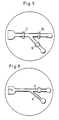
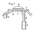
- a pressure wave generator in the form of a piezo column (11) is arranged on the waste channel (5) and is provided with a plunger (12) which can be pushed into the channel (Fig. 5, 7).
- the opening through which the plunger (12) projects into the channel (5) is provided with a vacuum-tight bushing (7).
- the plunger (12) protrudes more or less into the channel (5).
- Based on predefined algorithms or signal windows predefined on the evaluation electronics it is possible to preselect which types of cells with certain properties are to be sorted out. Whenever such a cell has been measured, the electronics make the decision to switch on the piezo column (11).
- the pressure wave generator on the sorting channel (4).
- This alternative is shown in Fig. 6.
- the plunger (12) of the piezo column (11) has to move in the opposite direction, so that a negative pressure wave (suction) is used.
- liquid flow flows continuously into both channels so that the laminar flow is maintained. If one channel is completely closed, the laminar flow would be dissolved and the central particle flow would mix with the envelope flow.
- the laminar particle flow is briefly deflected into the sorting channel (4) (FIGS. 8 and 9).
- suitable electronic means time control
- the flow speed of the laminar flow in this embodiment example is about 0.20 to 2 m / sec depending on the pressure or vacuum applied to transport the flows.
- the delay time between the measurement of the cell property and the shading of the piezo column varies, in this exemplary embodiment it is between 20 and 200 microseconds. This time also depends on how close the measuring point is before the branching.
- FIG. 9 shows how a short liquid column is derived from the waste channel flow into the sorting channel by switching on the piezo column.
- a further measuring point (24) can be arranged in the sorting channel (11), which is illuminated and observed by the same objective (Fig. 4.5). This means that every cell that passes this second measuring point delivers a second measuring signal. Because only the sorted cells are to flow into this channel, the measured values of the sorted cells are obtained without this
- FIG. 10 shows a schematic view of a particle sorting device, in which the individual liquid containers are shown in their arrangement relative to the sorting device.
- 11 shows the result of a sorting of different size classes of DNA cells. 11 shows the number of all cells (y-axis) in their size class distribution (x-axis). If the If the measuring apparatus is set to G 1 , the associated cells of this size class are sorted; if the measuring window is set to G, the number of cells belonging to this measured value.
- the distribution of the cells sorted out with the window G is shown in FIG. 11 center, while the distribution of the G, cells is shown in FIG. 11 below.
- the method is particularly applicable to all particles in the size range from 1 ⁇ m to a few 100 ⁇ m.
Landscapes
- Chemical & Material Sciences (AREA)
- Health & Medical Sciences (AREA)
- General Health & Medical Sciences (AREA)
- Dispersion Chemistry (AREA)
- Physics & Mathematics (AREA)
- Analytical Chemistry (AREA)
- Pathology (AREA)
- Biochemistry (AREA)
- General Physics & Mathematics (AREA)
- Immunology (AREA)
- Life Sciences & Earth Sciences (AREA)
- Clinical Laboratory Science (AREA)
- Hematology (AREA)
- Fluid Mechanics (AREA)
- Chemical Kinetics & Catalysis (AREA)
- Investigating Or Analysing Biological Materials (AREA)
- Apparatus Associated With Microorganisms And Enzymes (AREA)
- Sampling And Sample Adjustment (AREA)
- Measuring Or Testing Involving Enzymes Or Micro-Organisms (AREA)
- Cleaning In General (AREA)
Abstract
Description
- Die vorliegende Erfindung betrifft ein Verfahren zum automatischen Sortieren von mikroskopischen Partikeln, bei dem die Partikel in einer Flüssigkeit suspendiert durch einen geschlossenen Kanal geführt werden und dabei eine Messstelle, in der die auszusortierenden Partikel ein Signal auslösen, und eine anschliessende Verzweigung passieren, und eine Vorrichtung zur Durchführung des Verfahrens mit einem Zuführkanal für den Partikelstrom, einem Messkanal, einer im Messkanal angeordneten Messstelle, einer Verzweigung des Messkanals in einen Sortierkanal und einen Abfallkanal und einem Druckwellengenerator.
- Es gibt mikrophotometrisch Verfahren zur Messung morphologischer und biochemischer Eigenschaften von makroskopischen Partikeln, Zellen, Blutzellen, Tumorzellen etc. Diese Verfahren basieren darauf, dass in einem photometrischen Apparat Licht, das von jedem einzelnen in Flüssigkeit suspendierten und durch eine Messstelle, die Durchflussmesskammer, hindurchgesaugten oder - gedrückten Partikel ausgeht, mit Hilfe lichtempfindlicher Detektoren (Photomultiplier, Photozelle) erfasst und entsprechend seiner Intensität und/oder zeitlichen Verteilung gemessen wird. Das Ergebnis solcher Messungen an einzelnen Zellen sind Histogramme (Impulshöhenverteilungen). Derartige Verfahren erlauben die Messung von bis zu einigen tausend Zellen pro Sekunde. Das Hauptanwendungsgebiet ist die Zellbiologie und hier insbesondere die Krebszellforschung sowie die experimentelle oder quantitative Zytologie.
- Es wurden zusätzlich Verfahren vorgeschlagen, die Zellen zunächst einzeln zu vermessen bzw. deren biochemische oder morphologische Eigenschaften zu messen und unmittelbar im Anschluss daran diese aufgrund vorwählbarer Kriterien zu sortieren. Solche Sortiervorrichtungen arbeiten z.B. nach folgendem Prinzip: Nach der Erfassung der Partikeleigenschaft innerhalb der Durchflussmesskammer oder in einem feinen freien eine Porenoffnung verlassenden Strahl wird der Suspensionsstrahl mit Hilfe eines Piezo-Transducers in homogene feine Tröpfchen von einigen µm bis zu einigen 10 µm Durchmesser zerlegt. Unter der Annahme, dass sich zu einer bestimmten Zeit nach der photometrischen Messung eine bestimmte auszusortierende Zelle im Suspensionsstrahl unmittelbar vor der Loslösung dieses partikeltragenden Flüssigkeitsanteils als Tröpfchen befindet, wird der Flüssigkeitsstrahl elektrisch geladen. Das bedeutet, dass auch das unmittelbar danach sich loslösende Tröpfchen geladen ist Die Kette der geladenen und ungeladenen Tröpfchen wird nun an einem elektrostatisch geladenen Elektrodenpaar vorbeigeführt. Hier werden nur die geladenen Tröpfchen in der gewünschten Weise abgelenkt und in einem Gefäss aufgefangen. Es sind Vorrichtungen bekannt, diese Zellen sogleich in Kulturgefässen zu deponieren, um z.B. Zelllinien zu züchten, die auf jeweils eine aussortierte besondere Zelle zurückgehen. Derartige Verfahren werden z.B. in der Gentechnologie eingesetzt.
- Im Unterschied zu diesem "offenen" Sortiersystem wurden auch geschlossene Anordnungen vorgeschlagen (Zöld, oder Wiecorek oder Kamentsky). Die von Kamentsky beschriebene Anordnung benutzt einen Piezo-Transducer zur kurzzeitigen Störung eines Partikelstromes, der, umgeben von teilchenfreier Lösung, eine Messkammer passiert Jede von einem interessierenden Partikel initiierte Störung des Partikelstromes soll dazu führen, dass das betreffende Partikel in den an sich teilchenfreien Hüllstrom gelangt, von wo es in eine separate Auffangvorrichtung geleitet wird.
- Die von Wiecorek et al. beschriebene Vorrichtung bedient sich eines kapillaren Kanalsystems mit einer z.B.
- Y-förmigen Verzweigung, die sich in Fiiessrichtung der Suspension hinter der Messstelle befindet. In jedem Arm der Y-förmigen Verzweigung befindet sich ein mikroskopisch kleines Luftventil. An Piezo-membranen befestigte Stössel mit kleinen Kolben öffnen und schliessen diese Ventile entsprechend der Sortierentscheidung, die aufgrund jedes einzelnen Messwertes der Zellen getroffen wird. Das Oeffnen eines Ventils führt in dem System, das mit Vakuum betrieben wird, zum Einströmen von Luft in den betreffenden Arm des Kanalsystems und damit zu einer Verringerung der Fliessgeschwindigkeit. Bei richtiger Wahl der Verzögerungszeit, die zwischen der Messung einer Zelle und dem Oeffnen eines Ventils liegt, kann erreicht werden, dass die interessierenden Zellen in den einen Ast und die nichtinteressierenden Zellen in den zweiten Ast des Kapillarsystems fliessen. Die Sortiervorrichtung kann mit einem oder zwei gegensinnig arbeitenden Ventilen betrieben werden.
- Eine weitere, von Zöld vorgeschlagene, Sortiervorrichtung arbeitet ebenfalls mit einem geschlossenen sich verzweigenden Kapillarsystem, in dem die einzelnen Kanaläste durch elektrische Entladung zwischen Mikroelektroden und dadurch bewirkte "Gasbildung" mehr oder weniger verschlossen werden, um die interessierenden Zellen in den jeweils gewünschten Kanal zu lenken.
- Bei dem Tröpfchen-Sortierer handelt es sich um ein offenes System, in dem mikroskopisch kleine, die Zellen enthaltende Tröpfchen (Nebeltröpfchengrösse) im freien Fall an elektrisch geladenen Elektrodenplatten vorbeigeführt werden müssen. Zunächst ist es schwierig, die Zeit fastzulegen, die zwischem dem Messen und dem Laden des sobald vom Flüssigkeitsstrom sich lösenden Tröpfchens vergeht Diese Zeit muss weitgehend empirisch ermittelt werden. Die Qualität des Sortiervorganges (Reinheit der Probe) muss umständlich dadurch ermittelt werden, dass die "sortierten" Zellen erneut gemessen werden.
- Ein entscheidender weiterer Nachteil dieser Anordnung besteht darin, dass die mikroskopisch kleinen Tröpfchen zu einem beträchtlichen Teil sich nicht in der gewünschten Weise in das Auffanggefäss bewegen. Aufgrund komplizerter Ladungsverhältnisse der Tröpfchen einerseits und der Geräteteile andererseits, sowie wegen der Kleinheit der Tröpfchen und der Anfälligkeit durch Luftströmungen bewegt sich ein beträchtlicher Anteil der Tröpfchen unkontrolliert in den Raum. Dies ist von grösster Bedeutung, weil die Zellen i.a. mit fluoreszierenden Farbstoffen, die in der Regel mutagen und cancerogen sind, gefärbt sind oder radioaktive Stoffe (z.B. 3H-Thymidin) enthalten. Das sich bildende Aerosol mit derartig markierten Zellen stellt eine reale Gefahr für das Bedienungspersonal dar, das sich durch Einatmen beträchtlich kontaminieren kann.
- Ein weiterer Nachteil solcher offener Sortiersysieme besteht darin, dass sich diese nicht über längere Zeit unter sterilen Bedingungen betreiben lassen. Dies wäre allerdings wichtig, weil die sortierten Zellen häufig das Ausgangsmaterial für neue Zellkulturen sein sollen.
- Der Nachteil der von Kamentsky vorgeschlagenen geschlossenen Anordnung besteht darin, dass nach jedem einzelnen Sortiervorgang, der je eine Störung des Zentralstrahles, d.h. eine Vermischung des Zentralstrahles mit dem Hüllstrom voraussetzt, eine vergleichsweise lange Zeit vergeht, bis sich der Zentralstrahl mit den Zellen wieder etabliert und stabilisiert hat. Ausserdem ist die Aussonderung interessierender Zellen erheblich vom Zufall abhängig: nicht alle gewünschten Zellen bewegen sich durch die Piezo-Störung weit genug vom ehem. Zentralstrahl weg, um sicher aus der Peripherie des Flüssigkeitsstromes abgeführt werden zu können. Das System, das seit fast 20 Jahren bekannt ist, konnte nicht realisiert werden, es führt nicht zu brauchbaren Sortierergebnissen.
- Die von Zöld vorgeschlagene Anordnung ist nicht geeignet, Zellen mit dem Ziel zu sortieren, diese weiter zu kultivieren. Zellen sind rel. fragil; sie verlieren durch die erforderlichen "Explosionen" ihre Vitalität Das System ist zudem sehr aufwendig wegen der beträchtlichen Entladungen, die kurzzeitig und mit hoher Frequenze erfolgen sollen.Die sich bildenden Gase müssen zudem schnell abgeführt werden; Gase würden wegen der Elastizität und der Neigung des Systems zu Eigenschwingungen den Sortierablauf stören.
- In der Anordnung von Wiecorek et al. erweisen sich aus ähnlichen Gründen die eingeführten Luftmengen als nachteilig. Die Anordnung ist dadurch relativ langsam bzw. wegen der Luftelastizität trage und schwinganfällig. Die mikroskopisch kleinen Ventile sind schwer herzustellen, störanfällig und wartungsaufwendig, wenn man bedenkt, dass die Lufteintrittsschlitze im geöffneten Zustand nur eine Weite von einigen um bis wenige 10 µm haben. Der Sortiervorgang erfordert eine immer wieder zu kontrollierende und zu korrigierende Feineinstellung der Weite der Lufteintrittsöffnungen. Die erforderliche Luftzufuhr erschwert einen sterilen Betrieb der Anordnung.
- Der Erfindung liegt die Aufgabe zugrunde, ein Sortierverfahren und eine Vorrichtung bereitzustellen, die nicht mit den Nachteilen bekannter Systeme behaftet sind und in denen insbesondere Partikel in einem geschlossenen System steril, zuverlässig und schonend sortiert werden.
- Gemäss der vorliegenden Erfindung wird diese Aufgabe gelöst durch ein Sortierverfahren der eingangs angegebenen Art, das sich dadurch auszeichnet, dass durch das Signal in einem der beiden Kanäle hinter der Verzweigung eine Druckwelle erzeugt wird, welche den die Partikel enthaftenden Strom (Partiketstrom) an der Verzweigung für die Dauer des Partiketdurchgangs umleitet.
- Eine Vorrichtung zur Durchführung dieses Verfahrens zeichnet sich nach der Erfindung dadurch aus, dass der Druckwellengenerator in einem der beiden von der Verzweigung wegführenden Kanäle angeordnet ist.
- Der Verzweigungswinkel liegt vorzugsweise zwischen 10° und 45°. Er kann aber mehr sein oder auch 0°, d.h. eine Trennwand wird den einzigen Kanal in einem Abfallkanal und einem Sortierkanal trennen.
- Die zu sortierenden Partikel werden vorzugsweise in einem Zertralstrahl, der von teilchenfreier Lösung (z.B. Wasser) umgeben ist, einer Messstelle zugeführt Hier werden sie z.B. mit Hilfe einer mikroskopischen Auflichlanordnung durch ein Mikroskopobjektiv hindurch zur Fluoreszenz engeregt. Es können auch andere Messungen wie Streulichtmessung oder Messung des elektrischen Widerstandes ausgeführt werden. Jedes Messsignal wird entsprechend seiner Amplitude oder der zeitlichen Verteilung (Dauer) mit an sich bekannten Mitteln analysiert (z.B. mit Hilfeeines Vielkanalanalysators oder eines Rechners). Soll ein Partikel aussortiert werden, wird ein normiertes Signal, das auf das betreffende Messsignal zurückgeht, zu einem Hochspannungsimpulsgeber geleitet, der nach einer von der Fliessgeschwindigkeit und dem Abstand zwischen der Messstelle und der Kanalverzweigung abhängenden Zeit ein Hochspannungssignal zu einer Piezokristallsäule leitet Eine solche Säule dehnt sich z.B. bei einer angelegten Gleichspannung bzw. während eines Signals von 1000 V µm 20 bis 40 µm aus. Diese Piezosäule weist eine Verlängerung in Form eines Stössels auf. Dieser Stössel befindet sich in einer vakuumdichten Buchse in der Messkammer im Bereich eines der beiden abführenden Kapillarkanäle. Bei Anliegen einer Hochspannung bewegt sich der Stössel einige 10 µm in Richtung quer zum Kanal. Der zeitliche Verlauf dieser Bewegung entspricht der Form des Hochspannungssignals. Zwei Effekte können hier ausgenutzt werden:
- 1. Wenn der Stössel in den Kanal hineinragt, wird der Querschnitt dieses Kanals eingeengt Es fliesst weniger Flüssigkeit in Richtung des Auffanggefässes, das mit diesem Kanal verbunden ist Wichtig ist, dass die Dimensionen der beiden Kanalzweige so gewählt werden, dass die Partikel normalerweise, d.h. bei nichtangeregter Piezosäule, in den Abfallkanal fliessen. Dies kann auch durch geeignete Wahl der die Fliessgeschwindigkeit beeinflussenden Druckverhältnisse (Vakuumverhältnisse) erreicht werden.
- In den zweiten Kanal fliesst im Ruhezustand lediglich ein Teil des Partikelfreien Hüllstromes. Die durch die Anregung der Piezosäule verursachte Verengung führt dazu, dass je nach Dauer des anliegenden Hochspannungssignals ein Teil der Partikel enthaltenden Flüssigkeitssäule in den Sortierkanal abgelenkt wird. Dies wiederholt sich bei jedem zu sortierenden Partikel bis zu 1000 mal pro Sekunde.
- 2. Wenn sich der Stössel unter dem Niveau des Kanals befindet, (z.B. in einem von dem Kanal abzweigenden Blindkanal) verursacht die Anregung der Piezosäule eine Druckwelle, die sich in beide Richtungen in dem der Piezosäule zugehörenden Kanal fortsetzt. Diese Druckwelle verursacht eine verzögerungsfreie Ablenkung des die Partikel enthaltenden Zentralstrahles in den Sortierkanal. Damit erfolgt eine sehr präzise und beliebig kurzzeitige Ablenkung des Partikelstromes in den Sortierkanal. Der Stössel ist hierbei dem Abfallkanal zugeordnet
- Von den beiden Effekten ist der zweite der dominierende. Dieser tritt sowohl dann auf, wenn sich das Stösselende unter dem Kanalboden befindet als auch dann, wenn der Stössel in den Kanal hineinreicht
- Der Vorgang lässt sich bis zu 1000 mal pro Sekunde wiederholen, was einer Sortiergeschwindigkeit von 1000 Zellen/Sekunde entspricht.
- Es ist auch möglich, diesen Vorgang dadurch zu steuern, dass man statt der spannungsabhängigen Längenausdehnung der Piezosäule oder anderer mechanischen Vorrichtung z.B. eines Schrittmotors genau umgekehrt arbeitet Von einem hohen Spannungsniveau ausgehend werden kurze -Impulse generiert, die zu einer Verkürzung der Piezosäule führen. Das führt zu kurzzeitigen neg. Druckstössen, wodurch die Zellen in den gewünschten Kanal hineingesaugt werden. Hierzu muss sich der Stössel in dem Sortierkanal befinden. Aus Gründen der Schonung der Zellen und des sterilen Arbeitens ist es aber zweckmässiger, mit Druckwellen zu arbeiten, die von der im Abfallkanal installierten Piezosäule kommen.
- Die Vorrichtung der vorliegenden Erfindung besitzt die Vorteile, dass sie ein geschlossenes System aufweist und leicht sterilisierbar ist. Es verursacht keine Kontamination der Umgebung und keine Gefährdung des Personals. Da es keine Gase im System gibt, gibt es auch keine Elastizität. Es ist also schwingunanfällig und weist eine besonders schnelle Sortier geschwindigkeit auf.
- In der Praxis zeigte sich ein bemerkenswerter Vorteil: das System sortiert entweder richtig oder gamicht - damit sind, abgesehen von statistichen Koinzidenzen bei zu grosser Zelldichte, Fehlsortierungen nicht möglich.
- Die Wahl der Zeitverzögerung zwischen Messen und Ablenken (Hochspannungssignal) ist sehr einfach, da man im Mikroskopokular die abgelenkten Zellen einzeln zur Einstellung in Form eines Striches sieht Wird richtig sortiert, ist der an gleicher Stelle im Bereich der Verzweigung liegende "Umlenkpunkt" der sortierten Zellen deutlich sichtbar an immer der gleichen Stelle. Im Unterschied zu anderen Systemen sind die Kanäle mit 100 bis 500 µm besonders weit -dadurch wenig störanfällig durch Schmutzpartikel.
- Weitere Merkmale, Einzelheiten und Vorteile der Erfindung ergeben sich aus der folgenden Beschreibung einer bevorzugten Ausführungsform der Erfindung.
- Der Erfingungsgegenstand wird nun anhand eines in den Zeichnungen dargestellten Ausführungsbeispiels erläutert. Die Zeichnungen zeigen in
- Fig. 1 eine Perspektivansicht einer Partikelsortiervorrichtung.
- Fig. 2 einen Teilschnitt durch eine Partikelsortiervorrichtung für die Verwendung von Auflicht-Fluoreszenz
- Fig. 3 einen Teilschnitt durch eine Partikelsortiervorrichtung für die Verwendung von Durchlicht (Fluoreszenz, Absorption, Streulicht).
- Fig. 4 eine schematische Aufsicht einer Partikelsofiervorrichtung
- Fig. 5 & 6 schematische Aufsichten von Teilen von Partikelsortiervorrichtungen
- Fig. 7 einer Seitenschnitt einer Partikelsortiervorrichtung
- Fig. 8 & 9 schematische Darstellungen von der Sortierung einer Partikel
- Fig. 10 eine schematische Darstellung einer Partikelsortiervorrichtung mit Vorrats- und Ausfuhrflüssigkeitsbehältem
- Fig. 11 ein Histogramm von auf der Grundlage von Unterschiedlichen DNS-Gehalten sortierten DNS Zellen
- Das Ausführungsbeispiel wurde speziell für die Sortierung von Zellen mit verschiedanen DNS-Gehalten durch die Messung biochemischer Eigenschaften von Ehrlich-Ascites-Tumorzellen der Maus durch die Bestimmung des DNS-Gehaltes konzipiert Diese Messung beruht darauf, dass die zu messenden Zellen nach Anfärbung mit dem fluoreszierenden Agens Fluoreszenzlicht aussenden, wenn sie in der Messanordnung mit kurzwelligem Licht angeregt werden.
- Wie aus Fig 1 und 4 ersichtlich, werden die fluoreszenzmarkierten Zellen durch einen Zuführkanal (13), der im allgemeinen aus einem dünnen Röhrchen mit einem Innendurchmesser von 100 bis 300 µm besteht, einem Messkanal (1) zugeführt. Der Messkanal mit einer Breite von 1 bis 5 mm weist eine zweite Zuführung (14) für teilchenfreies Wasser (oder eine andere Lösung als Dispersionsmedium für die Zellen) (4) auf. Wenn in dem Messkanal (1) sowohl die Zellsuspension durch das Röhrchen (13) als auch die teilchenfreie Flüssigkeit einfliessen, bildet sich ein laminarer Strom von Zellen, der umgeben ist von zellfreier Lösung. Dieser Strom ist im Messkanal (1) sehr stabil. Der Messkanal hat einen Querschnitt von z.B. 100 µm mal 200 µm, er ist also flach bei Betrachtung durch ein Messobjektiv (18). Der Messkanal weist eine Verzweigung (3) in einer Sortierkanal (4) und einen Abfallkanal (5) auf. In den Abfallkanal (5) strömt der Zellstrom, wenn er unbeinflusst ist. Die auszusortierenden Zellen werden in den Sortierkanal geleitet
- In Fliessrichtung kurz vor dieser Verzweigung befindet sich eine Messstelle (2), die durch das Messobjektiv beobachtet wird (Fig. 2,3). Im Bereich dieser Messstelle werden die Zellen, die sich einzeln durch sie hindurchbewegen,zur Fluoreszenz angeregt Das Fluoreszenzlicht gelangt durch das Messobjektiv zu einem Photomultiplier (15) zur Messung der Intensität der jeder einzelnen Zelle zugeordneten Messsignale. Diese Messsignale werden mit elektronischen Mitteln registriert und klassifiziert.
- Anstelle der Verwendung nur eines Objektivs für die Beleuchtung der Messstelle und für die Sammlung des Fluoreszenzlichtes (Auflichtfluoreszenzmessung) kann auch ein separates Objektiv für die Sammlung des Fluoreszenzlichtes verwendet werden (Durchlichtanordnung).
- Am Abfallkanal (5) ist ein Druckwellengenerator in Form einer Piezosäule (11) angeordnet, die mit einem in den Kanal einschiebbaren Stössel (12) versehen ist (Fig. 5,7). Die Oeffnung, durch die der Stössel (12) in den Kanal (5) ragt, ist mit einer vakuumdichten Buchse (7) versehen. Je nachdem, ob die Piezosäule mit einem Signal angeregt wird oder nicht, ragt der Stössel (12) mehr oder weniger weit in den Kanal (5). Aufgrund vorgegebener Algorithmen bzw. an der Auswerteelektronik vorgegebener Signalfenster kann vorgewählt werden, welche Arten von Zellen mit bestimmten Eigenschaften aussortiert werden sollen. Immer dann, wenn eine solche Zelle gemessen wurde, trifft die Elektronik die Entscheidung, die Piezosäule (11) durchzuschalten.
- Selbstverständlich wäre es auch möglich, den Druckwellengenerator am Sortierkanal (4) anzuordnen. Diese Alternative ist in Fig. 6 gezeigt. Hierzu muss sich der Stössel (12) der Piezosäule (11) in umgekehrter Richtung bewegen, so dass mit einer negativen Druckwelle (Sog) gearbeitet wird.
- Zu beachten ist, daß der Flüssigkeitsstrom kontinuierlich in beide Kanäle fließt, damit der Laminarfluß erhalten bleibt Bei völligem Verschließen des einen Kanals würde der Laminarstrom aufgelöst und sich der zentrale Partikelstrom mit dem Hüllstrom vermischen.
- Wenn im Falle der Verwendung einer Druckwelle die Piezosäule kurzzeitig argeregt wird, kommt es zu einer kurzzeitigen Ablenkung des laminaren Partikelstromes in den Sortierkanal (4) (Fig. 8 und 9). Mit Hilfe geeigneter elektronischer Mittel (Zeitsteuerung) wird dafür Sorge getragen, dass die Piezosäule mit der richtigen Verzögerung durchgeschaltet wird, damit das immer genau dann erfolgt, wenn sich die zu sortierenden Zellen unmittelbar vor der Verzweigung befinden. Die Fliessgeschwindigkeit des laminaren Stromes beträgt bei diesem Ausführungsbeospiel etwa 0.20 bis 2 m/sec je nach angelegtem Druck oder Vakuum zum Transport der Ströme.
- Entsprechend der gewünschten Fliessgeschwindigkeit wird die verzögerungszeit zwischen der Messung der Zelleigenschaft und dem Durchschatten der Piezosäule variiert sie liegt bei diesem Ausführungsbeispiel zwischen 20 und 200 microsec. Diese Zeit hängt auch davon ab, wie nahe die Messstelle vor der Verzweigung liegt Fig. 9 zeigt im Vergleich zu Fig. 8, wie durch Einschaltung der Piezosäule eine kurze Flüssigkeitssäule aus dem Abfallkanalstrom in den Sortierkanal abgeleitet wird.
- Im Sortierkanal (11) kann eine weitere Messstelle (24) angeordnet sein, die durch dasselbe Objektiv beleuchtet und beobachtet wird (Fig. 4,5). Das bedeutet dass jede Zelle, die diese zweite Messstelle passiert ein zweites Messsignal liefert Da in diesen Kanal nur die aussortierten Zellen fliessen sollen, erhält man aus diese Weise die Messwerte der aussortierten Zellen, ohne
- daß die aussortierte Probe in einem zweiten Meßvorgang erneut gemessen werden muß.
- In Fig. 10 ist eine schematische Ansicht einer Partikelsortiervorrichtung gezeigt, bei der die einzelnen Flüssigkeitsbehälter in ihrer Anordnung zur Sortiervorrichtung gezeigt sind.
- Fig. 11 zeigt das Ergebnis einer Sortierung verschiedener Größenklassen von DNA-Zellen. Fig. 11 oben zeigt die Anzahl aller Zellen (y-Achse) in ihrer Größenklassenverteilung (x-Achse). Wenn die Meßapparatur auf G1 eingestellt ist, werden die zugehörigen Zellen dieser Größenklasse sortiert, bei Einstellung des Meßfensters auf G, die Zahl der diesem Meßwert zugehörigen Zellen.
- Die Verteilung der mit dem Fenster G, aussortierten Zellen zeigt Fig. 11 Mitte, während die Verteilung der G,-Zellen in Fig. 11 unten dargestellt sind.
- Als Anwendungsgebiete ergeben sich insbesondere:
- 1. Sortierung unterschiedlicher Blutzellen, Leukämiezellen,
- 2. Sortierung unterschiedlicher Zellen aus Gewebekulturen
- 3. Sortierung unterschiedlicher Turmorzellen aus menschlichen Tumorbiopsien, um diese vom Pathologen begutachten zu lassen. Dies ist deshalb von Bedeutung, weil in vielen Fallen nur sehr wenige Tumorzellen in den Proben vorhanden sind und eine vorangehende Anreicherung derselben die Diagnose erleichtert. Besondere Bedeutung hat das im Rahmen der Krebsfrüherkennung bei Reihenuntersuchungen z.B. bei der Vaginalzytologie.
- 4. Aussortierung bestimmter mit Oberflächenmarkem versehener Zellen nach Markierung mit Antikörpern z.B. zum Zwecke der Züchtung von bestimmten Zellklonen im Rahmen der Gentechnologie.
- 5. Isolierung bestimmter Heferassen im Gärungsgewerbe und in der Biotechnologie.
- 6. Sortierung unterschiedlicher mikroskopisch kleiner Partikel in der Industrie, Farbenpigmente, pharmazeutische Industrie.
- Die Methode ist insbesondere anwendbar bei allen Partikeln im Größenbereich von 1µm bis einige 100 µm.
-
- 1 Messkanal
- 2 Messstelle
- 3 Y-Verzweigung
- 4 Soritierkanal
- 5 Abfallkanal
- 6 Ausgang für die sortierten Zellen
- 7 Vakuumdichte Buchse
- 8 Abfall - mit Saugflasche (Pumpe) verbunden
- 11 Piezosäule
- 12 Stössel
- 13 Einlassfür Partikel-suspension (Zentralstrahl)
- 14 Zufuhr der Hüllstromlösung (Wasser)
- 15 Photomultiplier
- 16 Dichroitischer Spiegel (Lichtteiler)
- 17 Lichtquelle (UV oder Laser zum Fluoreszenzanregung)
- 18 Mess-Objektrv
- 19 Hülllösung
- 21 Deckglas
- 22 Partiketstrom
- 23 Kollektor
- 24 Zweite Messstelle
- 25 Wasservorrat
- 26 Zellvorrat
- 27 Abfall
- 28 Sortierte Zellen
Claims (12)
Priority Applications (1)
| Application Number | Priority Date | Filing Date | Title |
|---|---|---|---|
| AT85110397T ATE48477T1 (de) | 1984-09-11 | 1985-08-20 | Verfahren und vorrichtung zur sortierung von mikroskopischen partikeln. |
Applications Claiming Priority (2)
| Application Number | Priority Date | Filing Date | Title |
|---|---|---|---|
| CH432684 | 1984-09-11 | ||
| CH4326/84 | 1984-09-11 |
Publications (3)
| Publication Number | Publication Date |
|---|---|
| EP0177718A2 true EP0177718A2 (de) | 1986-04-16 |
| EP0177718A3 EP0177718A3 (en) | 1987-05-20 |
| EP0177718B1 EP0177718B1 (de) | 1989-12-06 |
Family
ID=4273983
Family Applications (1)
| Application Number | Title | Priority Date | Filing Date |
|---|---|---|---|
| EP85110397A Expired EP0177718B1 (de) | 1984-09-11 | 1985-08-20 | Verfahren und Vorrichtung zur Sortierung von mikroskopischen Partikeln |
Country Status (6)
| Country | Link |
|---|---|
| US (1) | US4756427A (de) |
| EP (1) | EP0177718B1 (de) |
| JP (1) | JPS61137062A (de) |
| AT (1) | ATE48477T1 (de) |
| CA (1) | CA1256825A (de) |
| DE (1) | DE3574617D1 (de) |
Cited By (15)
| Publication number | Priority date | Publication date | Assignee | Title |
|---|---|---|---|---|
| FR2628531A1 (fr) * | 1988-03-08 | 1989-09-15 | Chemunex Sa | Procede de recherche, de detection specifique et de numeration de micro-organismes, installation pour la mise en oeuvre dudit procede |
| WO1991015750A1 (en) * | 1990-04-09 | 1991-10-17 | Carri-Med Limited | Microfabricated device for biological cell sorting |
| EP0412431A3 (en) * | 1989-08-11 | 1992-03-04 | Becton Dickinson And Company | Method and apparatus for sorting particles with a moving catcher tube |
| DE19520298A1 (de) * | 1995-06-02 | 1996-12-05 | Bayer Ag | Sortiervorrichtung für biologische Zellen oder Viren |
| EP0727235A3 (de) * | 1995-02-17 | 1999-08-25 | GSF - Forschungszentrum für Umwelt und Gesundheit GmbH | Gerät zur Auftrennung des Teilchengrössenspektrums eines polydispersen Aerosols |
| EP1566434A3 (de) * | 2004-01-21 | 2006-11-29 | Hewlett-Packard Development Company, L.P. | Verfahren und Vorrichtung zum Sortieren von Teilchen |
| EP1557657A3 (de) * | 2004-01-21 | 2007-12-19 | Hewlett-Packard Development Company, L.P. | Vorrichtung und Verfahren zum Sortieren von Partikeln |
| EP1499453A4 (de) * | 2002-04-17 | 2009-11-04 | Cytonome Inc | Verfahren und vorrichtung zum sortieren von teilchen |
| US7963399B2 (en) | 2002-04-17 | 2011-06-21 | Cytonome/St, Llc | Method and apparatus for sorting particles |
| EP2139984A4 (de) * | 2007-04-20 | 2011-06-29 | Cellula Inc | Zellsortierungssystem und verfahren |
| EP2394740A1 (de) * | 2010-06-09 | 2011-12-14 | KIST-Europe Forschungsgesellschaft mbH | Vorrichtung zur Dosierung von Zellen, Verfahren zur Dosierung von Zellen sowie Verwendung der Vorrichtung |
| US8567608B2 (en) | 2002-04-17 | 2013-10-29 | Cytonome/St, Llc | Method and apparatus for sorting particles |
| US8623295B2 (en) | 2002-04-17 | 2014-01-07 | Cytonome/St, Llc | Microfluidic system including a bubble valve for regulating fluid flow through a microchannel |
| US9943847B2 (en) | 2002-04-17 | 2018-04-17 | Cytonome/St, Llc | Microfluidic system including a bubble valve for regulating fluid flow through a microchannel |
| US10994273B2 (en) | 2004-12-03 | 2021-05-04 | Cytonome/St, Llc | Actuation of parallel microfluidic arrays |
Families Citing this family (122)
| Publication number | Priority date | Publication date | Assignee | Title |
|---|---|---|---|---|
| US4936465A (en) * | 1987-12-07 | 1990-06-26 | Zoeld Tibor | Method and apparatus for fast, reliable, and environmentally safe dispensing of fluids, gases and individual particles of a suspension through pressure control at well defined parts of a closed flow-through system |
| US5101978A (en) * | 1989-11-27 | 1992-04-07 | The United States Of America As Represented By The Secretary Of The Army | Fluidic sorting device for two or more materials suspended in a fluid |
| US5199576A (en) * | 1991-04-05 | 1993-04-06 | University Of Rochester | System for flexibly sorting particles |
| US5412466A (en) * | 1991-07-26 | 1995-05-02 | Toa Medical Electronics Co., Ltd. | Apparatus for forming flattened sample flow for analyzing particles |
| US5672481A (en) * | 1991-10-23 | 1997-09-30 | Cellpro, Incorporated | Apparatus and method for particle separation in a closed field |
| US5395588A (en) * | 1992-12-14 | 1995-03-07 | Becton Dickinson And Company | Control of flow cytometer having vacuum fluidics |
| IT1272120B (it) * | 1993-03-22 | 1997-06-11 | Bio Rad Spd Srl | Camera di misurazione per citometro a flusso |
| GB9310557D0 (en) * | 1993-05-21 | 1993-07-07 | Smithkline Beecham Plc | Novel process and apparatus |
| WO1995035492A2 (de) * | 1994-06-17 | 1995-12-28 | Evotec Biosystems Gmbh | Verfahren und vorrichtung zur gezielten entnahme von komponenten aus komplexen mischungen |
| US5558832A (en) * | 1995-08-25 | 1996-09-24 | The Procter & Gamble Company | Apparatus for sorting substrate components according to size and method of sorting substrate components therewith |
| WO1997049925A1 (en) * | 1996-06-27 | 1997-12-31 | Weyerhaeuser Company | Fluid switch |
| US5941338A (en) * | 1996-08-01 | 1999-08-24 | Michelin Recherche Et Technique S.A. | Vehicle steering correction system |
| JP2002503334A (ja) * | 1996-09-04 | 2002-01-29 | テクニカル ユニバーシティ オブ デンマーク | 粒子の分離と分析用のマイクロフローシステム |
| JP4323571B2 (ja) | 1997-01-31 | 2009-09-02 | エックスワイ, インコーポレイテッド | 光学装置 |
| GB9707096D0 (en) * | 1997-04-08 | 1997-05-28 | Smithkline Beecham Plc | Novel device |
| AU7831798A (en) * | 1997-06-09 | 1998-12-30 | Guava Technologies, Inc. | Method and apparatus for detecting microparticles in fluid samples |
| US6071689A (en) | 1997-12-31 | 2000-06-06 | Xy, Inc. | System for improving yield of sexed embryos in mammals |
| US6149867A (en) | 1997-12-31 | 2000-11-21 | Xy, Inc. | Sheath fluids and collection systems for sex-specific cytometer sorting of sperm |
| ATE425448T1 (de) | 1998-05-16 | 2009-03-15 | Applera Corp | Optisches gerät insbesondere zur überwachung von dns-polymerasekettenreaktionen |
| US6818437B1 (en) | 1998-05-16 | 2004-11-16 | Applera Corporation | Instrument for monitoring polymerase chain reaction of DNA |
| US7498164B2 (en) * | 1998-05-16 | 2009-03-03 | Applied Biosystems, Llc | Instrument for monitoring nucleic acid sequence amplification reaction |
| US6086942A (en) * | 1998-05-27 | 2000-07-11 | International Brachytherapy S.A. | Fluid-jet deposition of radioactive material for brachytherapy devices |
| ES2296398T3 (es) | 1998-07-30 | 2008-04-16 | Xy, Inc. | Sistema de inseminacion equina artificial no quirurgica. |
| AU754644B2 (en) | 1998-08-21 | 2002-11-21 | Union Biometrica, Inc. | Instrument for selecting and depositing multicellular organisms and other large objects |
| US7208265B1 (en) | 1999-11-24 | 2007-04-24 | Xy, Inc. | Method of cryopreserving selected sperm cells |
| SE9904858D0 (sv) * | 1999-12-30 | 1999-12-30 | Acreo Ab | Flow controlling device and method |
| DK173796B1 (da) * | 2000-02-16 | 2001-11-05 | Nkt Res As | Fremgangsmåde til styring af strømning i et strømingssystem |
| JP4829460B2 (ja) * | 2000-03-21 | 2011-12-07 | ヒタチ ケミカル ダイアグノスティクス インコーポレーテッド | 密閉容器およびスクリーニング方法 |
| US6482652B2 (en) * | 2000-03-23 | 2002-11-19 | The Board Of Trustees Of The Leland Stanford Junior University | Biological particle sorter |
| EP2258173A3 (de) | 2000-05-09 | 2012-06-13 | Xy, Llc | Hochreines X-Chromosom-Lager und Y-Chromosom-Lagerpopulationen von Spermatozoiden |
| AU785424B2 (en) * | 2000-07-26 | 2007-05-17 | Regents Of The University Of California, The | Manipulation of live cells and inorganic objects with optical micro beam arrays |
| US6784420B2 (en) | 2000-11-13 | 2004-08-31 | Genoptix, Inc. | Method of separating particles using an optical gradient |
| US6936811B2 (en) * | 2000-11-13 | 2005-08-30 | Genoptix, Inc. | Method for separating micro-particles |
| US20030007894A1 (en) * | 2001-04-27 | 2003-01-09 | Genoptix | Methods and apparatus for use of optical forces for identification, characterization and/or sorting of particles |
| US6744038B2 (en) | 2000-11-13 | 2004-06-01 | Genoptix, Inc. | Methods of separating particles using an optical gradient |
| US20020123112A1 (en) * | 2000-11-13 | 2002-09-05 | Genoptix | Methods for increasing detection sensitivity in optical dielectric sorting systems |
| US20020121443A1 (en) * | 2000-11-13 | 2002-09-05 | Genoptix | Methods for the combined electrical and optical identification, characterization and/or sorting of particles |
| US6833542B2 (en) | 2000-11-13 | 2004-12-21 | Genoptix, Inc. | Method for sorting particles |
| US20020160470A1 (en) * | 2000-11-13 | 2002-10-31 | Genoptix | Methods and apparatus for generating and utilizing linear moving optical gradients |
| US6778724B2 (en) | 2000-11-28 | 2004-08-17 | The Regents Of The University Of California | Optical switching and sorting of biological samples and microparticles transported in a micro-fluidic device, including integrated bio-chip devices |
| US7713687B2 (en) | 2000-11-29 | 2010-05-11 | Xy, Inc. | System to separate frozen-thawed spermatozoa into x-chromosome bearing and y-chromosome bearing populations |
| CA2822983C (en) | 2000-11-29 | 2017-05-09 | Xy, Llc | System to separate frozen-thawed spermatozoa into x-chromosome bearing and y-chromosome bearing populations |
| US20030194755A1 (en) * | 2001-04-27 | 2003-10-16 | Genoptix, Inc. | Early detection of apoptotic events and apoptosis using optophoretic analysis |
| US20040009540A1 (en) * | 2001-04-27 | 2004-01-15 | Genoptix, Inc | Detection and evaluation of cancer cells using optophoretic analysis |
| US20030211009A1 (en) * | 2001-05-18 | 2003-11-13 | Buchanan Kris S. | Rapid multi-material sample input system |
| US7280207B2 (en) | 2001-07-25 | 2007-10-09 | Applera Corporation | Time-delay integration in a flow cytometry system |
| US7153699B2 (en) * | 2001-12-21 | 2006-12-26 | Cytonome, Inc. | Microfabricated two-pin system for biomolecule crystallization |
| US20070054408A1 (en) * | 2001-09-25 | 2007-03-08 | Cytonome, Inc. | Microfabricated two-pin system for biomolecule crystallization |
| US7179420B2 (en) * | 2001-10-25 | 2007-02-20 | Techelan, Llc | Apparatus comprising a particle sorter/dispenser and method therefor |
| US7252987B2 (en) * | 2001-12-06 | 2007-08-07 | Islet Technology, Inc. | System for analysis and selection of encapsulated cellular materials |
| AU2002364580A1 (en) * | 2001-12-18 | 2003-06-30 | University Of Wyoming | Apparatus and methods for high throughput analysis of particles in a translucent flowing liquid |
| US7452725B2 (en) * | 2002-01-10 | 2008-11-18 | Board Of Regents, The University Of Texas System | Flow sorting system and methods regarding same |
| US7223371B2 (en) * | 2002-03-14 | 2007-05-29 | Micronics, Inc. | Microfluidic channel network device |
| US20030175980A1 (en) * | 2002-03-14 | 2003-09-18 | Hayenga Jon W. | Ribbon flow cytometry and cell sorting |
| JP2004000144A (ja) * | 2002-03-29 | 2004-01-08 | Aisin Seiki Co Ltd | 細胞分離選別装置、細胞整列用基板 |
| WO2003089157A1 (en) * | 2002-04-17 | 2003-10-30 | Cytonome, Inc. | Method and apparatus for sorting particles |
| US7157274B2 (en) * | 2002-06-24 | 2007-01-02 | Cytonome, Inc. | Method and apparatus for sorting particles |
| US20070065808A1 (en) * | 2002-04-17 | 2007-03-22 | Cytonome, Inc. | Method and apparatus for sorting particles |
| US20030211461A1 (en) * | 2002-05-01 | 2003-11-13 | Genoptix, Inc | Optophoretic detection of durgs exhibiting inhibitory effect on Bcr-Abl positive tumor cells |
| US20040033539A1 (en) * | 2002-05-01 | 2004-02-19 | Genoptix, Inc | Method of using optical interrogation to determine a biological property of a cell or population of cells |
| US8211629B2 (en) | 2002-08-01 | 2012-07-03 | Xy, Llc | Low pressure sperm cell separation system |
| US8486618B2 (en) | 2002-08-01 | 2013-07-16 | Xy, Llc | Heterogeneous inseminate system |
| CA2534394C (en) | 2002-08-15 | 2013-01-08 | Xy, Inc. | High resolution flow cytometer |
| US6849459B2 (en) * | 2002-09-09 | 2005-02-01 | Cytonome, Inc. | Microfluidic chip for biomolecule crystallization |
| US20040053209A1 (en) * | 2002-09-12 | 2004-03-18 | Genoptix, Inc | Detection and evaluation of topoisomerase inhibitors using optophoretic analysis |
| US7169548B2 (en) | 2002-09-13 | 2007-01-30 | Xy, Inc. | Sperm cell processing and preservation systems |
| BR0314268A (pt) * | 2002-09-16 | 2005-07-26 | Cytonome Inc | Método e aparelho para separação de partìculas |
| US20040067167A1 (en) * | 2002-10-08 | 2004-04-08 | Genoptix, Inc. | Methods and apparatus for optophoretic diagnosis of cells and particles |
| US7160730B2 (en) * | 2002-10-21 | 2007-01-09 | Bach David T | Method and apparatus for cell sorting |
| US7161665B2 (en) * | 2002-12-18 | 2007-01-09 | University Of Wyoming | High resolution imaging fountain flow cytometry |
| US20040121474A1 (en) * | 2002-12-19 | 2004-06-24 | Genoptix, Inc | Detection and evaluation of chemically-mediated and ligand-mediated t-cell activation using optophoretic analysis |
| US20040121307A1 (en) * | 2002-12-19 | 2004-06-24 | Genoptix, Inc | Early detection of cellular differentiation using optophoresis |
| US7190450B2 (en) * | 2003-02-20 | 2007-03-13 | Yale University | Systems and methods for sorting aerosols |
| DK2959774T3 (da) | 2003-03-28 | 2019-05-13 | Inguran Llc | Fremgangsmåde til kryokonservering af sædceller |
| EP3023140B1 (de) | 2003-04-10 | 2019-10-09 | President and Fellows of Harvard College | Erzeugung und kontrolle von fluiden |
| WO2004104178A2 (en) | 2003-05-15 | 2004-12-02 | Xy, Inc. | Efficient haploid cell sorting for flow cytometer systems |
| CN104069784B (zh) | 2003-08-27 | 2017-01-11 | 哈佛大学 | 流体物种的电子控制 |
| US7745221B2 (en) | 2003-08-28 | 2010-06-29 | Celula, Inc. | Methods and apparatus for sorting cells using an optical switch in a microfluidic channel network |
| US20060115379A1 (en) * | 2003-10-17 | 2006-06-01 | Bach David T | Magnetostrictive pump |
| AU2004285960A1 (en) * | 2003-10-30 | 2005-05-12 | Cytonome/St, Llc | Multilayer hydrodynamic sheath flow structure |
| US20050103690A1 (en) * | 2003-11-19 | 2005-05-19 | Aisin Seiki Kabushiki Kaisha | Micro liquid control system |
| EP2260854A1 (de) | 2004-03-29 | 2010-12-15 | Inguran, LLC | Spermasuspensionen zur Sortierung in X- oder Y-Chromosomen-tragende angereicherte Populationen |
| AU2005266930B2 (en) | 2004-07-22 | 2010-09-16 | Inguran, Llc | Process for enriching a population of sperm cells |
| US7392908B2 (en) * | 2005-01-12 | 2008-07-01 | Beckman Coulter, Inc. | Methods and apparatus for sorting particles hydraulically |
| JP4047336B2 (ja) * | 2005-02-08 | 2008-02-13 | 独立行政法人科学技術振興機構 | ゲル電極付セルソーターチップ |
| US7618770B2 (en) | 2005-07-29 | 2009-11-17 | Xy, Inc. | Methods and apparatus for reducing protein content in sperm cell extenders |
| JP4745755B2 (ja) * | 2005-08-23 | 2011-08-10 | セイコーインスツル株式会社 | 分画マイクロチップ及び分画装置 |
| WO2007102839A2 (en) * | 2005-10-27 | 2007-09-13 | Applera Corporation | Optoelectronic separation of biomolecules |
| CN100551550C (zh) * | 2006-09-25 | 2009-10-21 | 瑞鼎科技股份有限公司 | 流体微粒分离装置 |
| JP4661942B2 (ja) * | 2008-05-13 | 2011-03-30 | ソニー株式会社 | マイクロチップとその流路構造 |
| EP3002489B1 (de) * | 2008-05-16 | 2017-09-20 | President and Fellows of Harvard College | Ventile und andere flusssteuerungen für fluidische systeme einschliesslich mikrofluidischer systeme |
| JP5382852B2 (ja) | 2009-02-06 | 2014-01-08 | 株式会社オンチップ・バイオテクノロジーズ | 使い捨てチップ型フローセルとそれを用いたフローサイトメーター |
| WO2010104993A2 (en) * | 2009-03-10 | 2010-09-16 | The Regents Of The University Of California | Fluidic flow cytometry devices and particle sensing based on signal-encoding |
| CN102753955B (zh) | 2010-01-15 | 2015-02-04 | 芯片生物技术株式会社 | 一次性芯片型流动室与利用其的细胞分选仪 |
| WO2012094325A2 (en) * | 2011-01-03 | 2012-07-12 | Cytonome/St. Llc | Method and apparatus for monitoring and optimizing particle sorting |
| US9657290B2 (en) | 2012-07-03 | 2017-05-23 | The Board Of Trustees Of The Leland Stanford Junior University | Scalable bio-element analysis |
| EP2876427B1 (de) * | 2012-07-18 | 2019-09-04 | Sony Corporation | Mikropartikelisolierungsvorrichtung und mikropartikelisolationsverfahren |
| JP6036496B2 (ja) * | 2012-07-24 | 2016-11-30 | ソニー株式会社 | 微小粒子分取方法 |
| EP2906928A4 (de) | 2012-10-15 | 2016-11-09 | Nanocellect Biomedical Inc | Systeme, vorrichtungen und verfahren zum sortieren von partikeln |
| US10371622B2 (en) | 2013-03-14 | 2019-08-06 | Inguran, Llc | Device for high throughput sperm sorting |
| US10662408B2 (en) | 2013-03-14 | 2020-05-26 | Inguran, Llc | Methods for high throughput sperm sorting |
| US9757726B2 (en) | 2013-03-14 | 2017-09-12 | Inguran, Llc | System for high throughput sperm sorting |
| EP4220124A1 (de) | 2013-03-14 | 2023-08-02 | Cytonome/ST, LLC | Hydrodynamische fokussierungsvorrichtung und verfahren |
| EP2971287B1 (de) | 2013-03-15 | 2019-08-14 | GPB Scientific, LLC | Mikrofluidische on-chip-verarbeitung von partikeln |
| EP3608022A1 (de) | 2013-03-15 | 2020-02-12 | The Trustees of Princeton University | Verfahren und vorrichtungen für reinigung mit hohem durchsatz |
| US12590955B2 (en) | 2013-03-15 | 2026-03-31 | Zeon Corporation | Methods and systems for processing particles |
| US20150064153A1 (en) | 2013-03-15 | 2015-03-05 | The Trustees Of Princeton University | High efficiency microfluidic purification of stem cells to improve transplants |
| US10343165B2 (en) * | 2013-09-05 | 2019-07-09 | Bio-Rad Laboratories, Inc. | On-demand particle dispensing system |
| EP3042178B1 (de) * | 2013-09-05 | 2019-08-21 | Bio-rad Laboratories, Inc. | Verfahren zur isolierung eines partikels aus einer fluidprobe |
| US8820538B1 (en) * | 2014-03-17 | 2014-09-02 | Namocell LLC | Method and apparatus for particle sorting |
| US10960396B2 (en) | 2014-05-16 | 2021-03-30 | Cytonome/St, Llc | Thermal activated microfluidic switching |
| JP6962563B2 (ja) | 2015-05-12 | 2021-11-05 | 株式会社オンチップ・バイオテクノロジーズ | 単一粒子解析方法およびその解析のためのシステム |
| CA2996529A1 (en) | 2015-08-24 | 2017-03-02 | Gpb Scientific, Llc | Methods and devices for multi-step cell purification and concentration |
| US10976232B2 (en) | 2015-08-24 | 2021-04-13 | Gpb Scientific, Inc. | Methods and devices for multi-step cell purification and concentration |
| JP7116975B2 (ja) * | 2016-08-31 | 2022-08-12 | フロイント産業株式会社 | 逸脱処理装置及び逸脱処理方法 |
| CN115254210A (zh) * | 2016-11-14 | 2022-11-01 | 浩康生物系统公司 | 用于分选目标颗粒的方法和装置 |
| US11579073B2 (en) * | 2017-02-07 | 2023-02-14 | Nodexus Inc. | Microfluidic system with combined electrical and optical detection for high accuracy particle sorting and methods thereof |
| US10272431B2 (en) * | 2017-02-18 | 2019-04-30 | Owl biomedical, Inc. | Microfabricated cell sorter using pressure pulse |
| US11982611B2 (en) | 2017-03-20 | 2024-05-14 | Nanocellect Biomedical, Inc. | Systems, apparatuses, and methods for cell sorting and flow cytometry |
| EP3797279A4 (de) * | 2018-07-11 | 2022-08-03 | The University of Hong Kong | Automatisches mikrofluidisches system zur kontinuierlichen und quantitativen sammlung von tröpfchen |
| JP7477378B2 (ja) | 2020-06-19 | 2024-05-01 | シスメックス株式会社 | 粒子ソーター、粒子分取方法およびマイクロ流路カートリッジ |
| US12246318B2 (en) | 2022-01-31 | 2025-03-11 | Tdk Corporation | Devices and methods for sensing and sorting particles |
Family Cites Families (8)
| Publication number | Priority date | Publication date | Assignee | Title |
|---|---|---|---|---|
| US3560754A (en) * | 1965-11-17 | 1971-02-02 | Ibm | Photoelectric particle separator using time delay |
| US3550771A (en) * | 1969-03-12 | 1970-12-29 | Us Army | Fluidic weighing and sorting system |
| BE793185A (fr) * | 1971-12-23 | 1973-04-16 | Atomic Energy Commission | Appareil pour analyser et trier rapidement des particules telles que des cellules biologiques |
| US3826364A (en) * | 1972-05-22 | 1974-07-30 | Univ Leland Stanford Junior | Particle sorting method and apparatus |
| GB1389553A (en) * | 1972-05-23 | 1975-04-03 | Legorreta G | Apparatus for investigating microscopic particles |
| JPS4946274A (de) * | 1972-09-12 | 1974-05-02 | ||
| US3827555A (en) * | 1973-03-05 | 1974-08-06 | Bio Physics Systems Inc | Particle sorter with segregation indicator |
| DE2716095C2 (de) * | 1977-04-12 | 1987-02-19 | Becton, Dickinson and Co., Paramus, N.J. | Verfahren zur Steuerung der Bewegungsbahn von in einem Elektrolyten suspendierten Teilchen und Vorrichtung zur Durchführung dieses Verfahrens |
-
1985
- 1985-08-20 EP EP85110397A patent/EP0177718B1/de not_active Expired
- 1985-08-20 DE DE8585110397T patent/DE3574617D1/de not_active Expired - Fee Related
- 1985-08-20 AT AT85110397T patent/ATE48477T1/de not_active IP Right Cessation
- 1985-09-10 CA CA000490295A patent/CA1256825A/en not_active Expired
- 1985-09-11 JP JP60201476A patent/JPS61137062A/ja active Pending
-
1987
- 1987-10-14 US US07/110,032 patent/US4756427A/en not_active Expired - Fee Related
Cited By (24)
| Publication number | Priority date | Publication date | Assignee | Title |
|---|---|---|---|---|
| FR2628531A1 (fr) * | 1988-03-08 | 1989-09-15 | Chemunex Sa | Procede de recherche, de detection specifique et de numeration de micro-organismes, installation pour la mise en oeuvre dudit procede |
| EP0333560A1 (de) * | 1988-03-08 | 1989-09-20 | Chemunex | Verfahren zur Bestimmung von mikro-organismen |
| WO1989008714A1 (fr) * | 1988-03-08 | 1989-09-21 | Chemunex | Procede de recherche, qualitatif ou quantitatif de micro-organismes, installation pour la mise en oeuvre dudit procede |
| EP0412431A3 (en) * | 1989-08-11 | 1992-03-04 | Becton Dickinson And Company | Method and apparatus for sorting particles with a moving catcher tube |
| WO1991015750A1 (en) * | 1990-04-09 | 1991-10-17 | Carri-Med Limited | Microfabricated device for biological cell sorting |
| EP0727235A3 (de) * | 1995-02-17 | 1999-08-25 | GSF - Forschungszentrum für Umwelt und Gesundheit GmbH | Gerät zur Auftrennung des Teilchengrössenspektrums eines polydispersen Aerosols |
| DE19520298A1 (de) * | 1995-06-02 | 1996-12-05 | Bayer Ag | Sortiervorrichtung für biologische Zellen oder Viren |
| US5837200A (en) * | 1995-06-02 | 1998-11-17 | Bayer Aktiengesellschaft | Sorting device for biological cells or viruses |
| US9943847B2 (en) | 2002-04-17 | 2018-04-17 | Cytonome/St, Llc | Microfluidic system including a bubble valve for regulating fluid flow through a microchannel |
| US10029263B2 (en) | 2002-04-17 | 2018-07-24 | Cytonome/St, Llc | Method and apparatus for sorting particles |
| EP1499453A4 (de) * | 2002-04-17 | 2009-11-04 | Cytonome Inc | Verfahren und vorrichtung zum sortieren von teilchen |
| US7963399B2 (en) | 2002-04-17 | 2011-06-21 | Cytonome/St, Llc | Method and apparatus for sorting particles |
| US11027278B2 (en) | 2002-04-17 | 2021-06-08 | Cytonome/St, Llc | Methods for controlling fluid flow in a microfluidic system |
| US10427159B2 (en) | 2002-04-17 | 2019-10-01 | Cytonome/St, Llc | Microfluidic device |
| US8567608B2 (en) | 2002-04-17 | 2013-10-29 | Cytonome/St, Llc | Method and apparatus for sorting particles |
| US8623295B2 (en) | 2002-04-17 | 2014-01-07 | Cytonome/St, Llc | Microfluidic system including a bubble valve for regulating fluid flow through a microchannel |
| US8727131B2 (en) | 2002-04-17 | 2014-05-20 | Cytonome/St, Llc | Method and apparatus for sorting particles |
| US9011797B2 (en) | 2002-04-17 | 2015-04-21 | Cytonome/St, Llc | Microfluidic system including a bubble valve for regulating fluid flow through a microchannel |
| US10029283B2 (en) | 2002-04-17 | 2018-07-24 | Cytonome/St, Llc | Method and apparatus for sorting particles |
| EP1566434A3 (de) * | 2004-01-21 | 2006-11-29 | Hewlett-Packard Development Company, L.P. | Verfahren und Vorrichtung zum Sortieren von Teilchen |
| EP1557657A3 (de) * | 2004-01-21 | 2007-12-19 | Hewlett-Packard Development Company, L.P. | Vorrichtung und Verfahren zum Sortieren von Partikeln |
| US10994273B2 (en) | 2004-12-03 | 2021-05-04 | Cytonome/St, Llc | Actuation of parallel microfluidic arrays |
| EP2139984A4 (de) * | 2007-04-20 | 2011-06-29 | Cellula Inc | Zellsortierungssystem und verfahren |
| EP2394740A1 (de) * | 2010-06-09 | 2011-12-14 | KIST-Europe Forschungsgesellschaft mbH | Vorrichtung zur Dosierung von Zellen, Verfahren zur Dosierung von Zellen sowie Verwendung der Vorrichtung |
Also Published As
| Publication number | Publication date |
|---|---|
| US4756427A (en) | 1988-07-12 |
| CA1256825A (en) | 1989-07-04 |
| EP0177718A3 (en) | 1987-05-20 |
| EP0177718B1 (de) | 1989-12-06 |
| DE3574617D1 (de) | 1990-01-11 |
| JPS61137062A (ja) | 1986-06-24 |
| ATE48477T1 (de) | 1989-12-15 |
Similar Documents
| Publication | Publication Date | Title |
|---|---|---|
| EP0177718B1 (de) | Verfahren und Vorrichtung zur Sortierung von mikroskopischen Partikeln | |
| DE2261695C2 (de) | Vorrichtung zur Schnellanalyse und zum Sortieren kleiner Teilchen | |
| DE10304653B4 (de) | Mehrparametrige Detektion in einem fluidischen Mikrosystem | |
| DE69031640T2 (de) | Verfahren und Gerät zum Sortieren von Teilchen mit einem beweglichen Auffangrohr | |
| DE69937353T2 (de) | Instrument zur analyse und selektiven verteilung von objektproben | |
| DE69709377T2 (de) | Mikrofliesssystem für die teilchenanalyse und trennung | |
| DE69328296T2 (de) | Verfahren und materialien zur bestimmung der teilchenzahl in einem durchflusszytometer | |
| EP0879408B1 (de) | Verfahren zum sortieren und zur gewinnung von biologischen objekten auf einem planaren träger durch freipräparieren mittels eines laserstrahles und anschliessendes wegkatapultieren durch einen laser-schuss | |
| DE69025256T2 (de) | Gerät und Verfahren zur Trennung von Teilchen aus flüssigkeitssuspendierten Teilchen in Zusammenhang mit deren Eigenschaften | |
| DE2246380C2 (de) | Vorrichtung zum Trennen bzw. Sortieren von Teilchen | |
| DE69521558T2 (de) | Vorrichtung und Verfahren zur Zytometrie unter Verwendung einer Kapillarküvette mit definiertem Volumen | |
| EP1311655B1 (de) | Vorrichtung und verfahren zum elektrischen kontaktieren von in einer flüssigkeit in suspension befindlichen biologischen zellen | |
| DE69901432T2 (de) | Selektive konzentration und anreicherungssortierung von flusszytometertropfen, basierend auf der analyse von tröpfchenvorläuferregionen | |
| DE69209886T2 (de) | Gerät zur Zellenanalyse im Urin | |
| DE102017122718A1 (de) | Verfahren und Vorrichtung zur optischen Untersuchung einer Vielzahl mikroskopischer Proben | |
| DE3315194A1 (de) | Verfahren zum trennen von in einer fluidprobe stroemenden teilchen | |
| WO2006053892A1 (de) | Mikrofluidisches system mit einer kanalaufweitung | |
| CH670890A5 (de) | ||
| DE69028399T2 (de) | Verfahren zum sichten von zellen oder geformten körpern mit ausgewählten eigenschaften unter benutzung eines nachweisparameters | |
| DE69223138T2 (de) | Verfahren und vorrichtung zum reihensichten mikroskopischer zellen unter verwendung von techniken zur streuung polarisierten lichts | |
| DE68928085T2 (de) | Verfahren zur auslese bestimmter zellen oder zellgebilden anhand von populationen mit ausgewählten merkmalen | |
| DE4017709C2 (de) | Verfahren und Vorrichtung zum gesteuerten Aussondern von fluiden Substanzen aus einer Fluidströmung | |
| EP4188607B1 (de) | Verfahren und fluidisches mikrosystem zur dielektrophoretischen manipulierung von suspendierten partikeln | |
| DE2056291A1 (de) | Vorrichtung zur Unterscheidung, zum Zahlen und Sortieren von Teilchen ent sprechend ihrer MikroStruktur | |
| DE10320956B4 (de) | Untersuchungsverfahren für biologische Zellen und zugehörige Untersuchungseinrichtung |
Legal Events
| Date | Code | Title | Description |
|---|---|---|---|
| PUAI | Public reference made under article 153(3) epc to a published international application that has entered the european phase |
Free format text: ORIGINAL CODE: 0009012 |
|
| AK | Designated contracting states |
Kind code of ref document: A2 Designated state(s): AT BE CH DE FR GB IT LI LU NL SE |
|
| PUAL | Search report despatched |
Free format text: ORIGINAL CODE: 0009013 |
|
| AK | Designated contracting states |
Kind code of ref document: A3 Designated state(s): AT BE CH DE FR GB IT LI LU NL SE |
|
| 17P | Request for examination filed |
Effective date: 19870612 |
|
| 17Q | First examination report despatched |
Effective date: 19881010 |
|
| GRAA | (expected) grant |
Free format text: ORIGINAL CODE: 0009210 |
|
| AK | Designated contracting states |
Kind code of ref document: B1 Designated state(s): AT BE CH DE FR GB IT LI LU NL SE |
|
| REF | Corresponds to: |
Ref document number: 48477 Country of ref document: AT Date of ref document: 19891215 Kind code of ref document: T |
|
| REF | Corresponds to: |
Ref document number: 3574617 Country of ref document: DE Date of ref document: 19900111 |
|
| GBT | Gb: translation of ep patent filed (gb section 77(6)(a)/1977) | ||
| ET | Fr: translation filed | ||
| ITF | It: translation for a ep patent filed | ||
| PLBE | No opposition filed within time limit |
Free format text: ORIGINAL CODE: 0009261 |
|
| STAA | Information on the status of an ep patent application or granted ep patent |
Free format text: STATUS: NO OPPOSITION FILED WITHIN TIME LIMIT |
|
| 26N | No opposition filed | ||
| REG | Reference to a national code |
Ref country code: CH Ref legal event code: PUE Owner name: AGROGEN-STIFTUNG |
|
| REG | Reference to a national code |
Ref country code: FR Ref legal event code: TP |
|
| NLS | Nl: assignments of ep-patents |
Owner name: AGROGEN EN K-MIDT LIAB. CO. LTD. BEIDE TE FREIBURG |
|
| ITTA | It: last paid annual fee | ||
| REG | Reference to a national code |
Ref country code: GB Ref legal event code: 732E |
|
| EPTA | Lu: last paid annual fee | ||
| EAL | Se: european patent in force in sweden |
Ref document number: 85110397.8 |
|
| ITPR | It: changes in ownership of a european patent |
Owner name: CESSIONE;ABROGEN ; K - MIDT LIAB. CO. LTD |
|
| PGFP | Annual fee paid to national office [announced via postgrant information from national office to epo] |
Ref country code: SE Payment date: 20000816 Year of fee payment: 16 |
|
| PGFP | Annual fee paid to national office [announced via postgrant information from national office to epo] |
Ref country code: NL Payment date: 20000831 Year of fee payment: 16 |
|
| REG | Reference to a national code |
Ref country code: GB Ref legal event code: 732E |
|
| REG | Reference to a national code |
Ref country code: FR Ref legal event code: TQ |
|
| NLS | Nl: assignments of ep-patents |
Owner name: AGROGEN |
|
| PGFP | Annual fee paid to national office [announced via postgrant information from national office to epo] |
Ref country code: GB Payment date: 20010808 Year of fee payment: 17 |
|
| PGFP | Annual fee paid to national office [announced via postgrant information from national office to epo] |
Ref country code: FR Payment date: 20010810 Year of fee payment: 17 |
|
| PG25 | Lapsed in a contracting state [announced via postgrant information from national office to epo] |
Ref country code: SE Free format text: LAPSE BECAUSE OF NON-PAYMENT OF DUE FEES Effective date: 20010821 |
|
| PGFP | Annual fee paid to national office [announced via postgrant information from national office to epo] |
Ref country code: AT Payment date: 20010822 Year of fee payment: 17 |
|
| PGFP | Annual fee paid to national office [announced via postgrant information from national office to epo] |
Ref country code: LU Payment date: 20010829 Year of fee payment: 17 |
|
| PGFP | Annual fee paid to national office [announced via postgrant information from national office to epo] |
Ref country code: BE Payment date: 20010921 Year of fee payment: 17 |
|
| REG | Reference to a national code |
Ref country code: GB Ref legal event code: IF02 |
|
| PG25 | Lapsed in a contracting state [announced via postgrant information from national office to epo] |
Ref country code: NL Free format text: LAPSE BECAUSE OF NON-PAYMENT OF DUE FEES Effective date: 20020301 |
|
| EUG | Se: european patent has lapsed |
Ref document number: 85110397.8 |
|
| NLV4 | Nl: lapsed or anulled due to non-payment of the annual fee |
Effective date: 20020301 |
|
| PGFP | Annual fee paid to national office [announced via postgrant information from national office to epo] |
Ref country code: DE Payment date: 20020808 Year of fee payment: 18 |
|
| PG25 | Lapsed in a contracting state [announced via postgrant information from national office to epo] |
Ref country code: LU Free format text: LAPSE BECAUSE OF NON-PAYMENT OF DUE FEES Effective date: 20020820 Ref country code: GB Free format text: LAPSE BECAUSE OF NON-PAYMENT OF DUE FEES Effective date: 20020820 Ref country code: AT Free format text: LAPSE BECAUSE OF NON-PAYMENT OF DUE FEES Effective date: 20020820 |
|
| PG25 | Lapsed in a contracting state [announced via postgrant information from national office to epo] |
Ref country code: BE Free format text: LAPSE BECAUSE OF NON-PAYMENT OF DUE FEES Effective date: 20020831 |
|
| BERE | Be: lapsed |
Owner name: *FONDATION AGROGEN Effective date: 20020831 Owner name: *AGROGEN Effective date: 20020831 |
|
| GBPC | Gb: european patent ceased through non-payment of renewal fee |
Effective date: 20020820 |
|
| PG25 | Lapsed in a contracting state [announced via postgrant information from national office to epo] |
Ref country code: FR Free format text: LAPSE BECAUSE OF NON-PAYMENT OF DUE FEES Effective date: 20030430 |
|
| REG | Reference to a national code |
Ref country code: FR Ref legal event code: ST |
|
| PGFP | Annual fee paid to national office [announced via postgrant information from national office to epo] |
Ref country code: CH Payment date: 20030731 Year of fee payment: 19 |
|
| PG25 | Lapsed in a contracting state [announced via postgrant information from national office to epo] |
Ref country code: DE Free format text: LAPSE BECAUSE OF NON-PAYMENT OF DUE FEES Effective date: 20040302 |
|
| PG25 | Lapsed in a contracting state [announced via postgrant information from national office to epo] |
Ref country code: LI Free format text: LAPSE BECAUSE OF NON-PAYMENT OF DUE FEES Effective date: 20040831 Ref country code: CH Free format text: LAPSE BECAUSE OF NON-PAYMENT OF DUE FEES Effective date: 20040831 |
|
| REG | Reference to a national code |
Ref country code: CH Ref legal event code: PL |