EP0177736A2 - Objet en matière plastique renforcé de fibres et procédé pour le formage d'objets - Google Patents
Objet en matière plastique renforcé de fibres et procédé pour le formage d'objets Download PDFInfo
- Publication number
- EP0177736A2 EP0177736A2 EP85110844A EP85110844A EP0177736A2 EP 0177736 A2 EP0177736 A2 EP 0177736A2 EP 85110844 A EP85110844 A EP 85110844A EP 85110844 A EP85110844 A EP 85110844A EP 0177736 A2 EP0177736 A2 EP 0177736A2
- Authority
- EP
- European Patent Office
- Prior art keywords
- blank
- fiber reinforced
- reinforced plastic
- plastic
- mould
- Prior art date
- Legal status (The legal status is an assumption and is not a legal conclusion. Google has not performed a legal analysis and makes no representation as to the accuracy of the status listed.)
- Granted
Links
Images






Classifications
-
- B—PERFORMING OPERATIONS; TRANSPORTING
- B29—WORKING OF PLASTICS; WORKING OF SUBSTANCES IN A PLASTIC STATE IN GENERAL
- B29C—SHAPING OR JOINING OF PLASTICS; SHAPING OF MATERIAL IN A PLASTIC STATE, NOT OTHERWISE PROVIDED FOR; AFTER-TREATMENT OF THE SHAPED PRODUCTS, e.g. REPAIRING
- B29C70/00—Shaping composites, i.e. plastics material comprising reinforcements, fillers or preformed parts, e.g. inserts
- B29C70/04—Shaping composites, i.e. plastics material comprising reinforcements, fillers or preformed parts, e.g. inserts comprising reinforcements only, e.g. self-reinforcing plastics
- B29C70/06—Fibrous reinforcements only
- B29C70/08—Fibrous reinforcements only comprising combinations of different forms of fibrous reinforcements incorporated in matrix material, forming one or more layers, and with or without non-reinforced layers
-
- B—PERFORMING OPERATIONS; TRANSPORTING
- B29—WORKING OF PLASTICS; WORKING OF SUBSTANCES IN A PLASTIC STATE IN GENERAL
- B29C—SHAPING OR JOINING OF PLASTICS; SHAPING OF MATERIAL IN A PLASTIC STATE, NOT OTHERWISE PROVIDED FOR; AFTER-TREATMENT OF THE SHAPED PRODUCTS, e.g. REPAIRING
- B29C43/00—Compression moulding, i.e. applying external pressure to flow the moulding material; Apparatus therefor
- B29C43/32—Component parts, details or accessories; Auxiliary operations
- B29C43/36—Moulds for making articles of definite length, i.e. discrete articles
- B29C43/361—Moulds for making articles of definite length, i.e. discrete articles with pressing members independently movable of the parts for opening or closing the mould, e.g. movable pistons
-
- B—PERFORMING OPERATIONS; TRANSPORTING
- B29—WORKING OF PLASTICS; WORKING OF SUBSTANCES IN A PLASTIC STATE IN GENERAL
- B29C—SHAPING OR JOINING OF PLASTICS; SHAPING OF MATERIAL IN A PLASTIC STATE, NOT OTHERWISE PROVIDED FOR; AFTER-TREATMENT OF THE SHAPED PRODUCTS, e.g. REPAIRING
- B29C70/00—Shaping composites, i.e. plastics material comprising reinforcements, fillers or preformed parts, e.g. inserts
- B29C70/04—Shaping composites, i.e. plastics material comprising reinforcements, fillers or preformed parts, e.g. inserts comprising reinforcements only, e.g. self-reinforcing plastics
- B29C70/06—Fibrous reinforcements only
- B29C70/08—Fibrous reinforcements only comprising combinations of different forms of fibrous reinforcements incorporated in matrix material, forming one or more layers, and with or without non-reinforced layers
- B29C70/081—Combinations of fibres of continuous or substantial length and short fibres
-
- B—PERFORMING OPERATIONS; TRANSPORTING
- B29—WORKING OF PLASTICS; WORKING OF SUBSTANCES IN A PLASTIC STATE IN GENERAL
- B29C—SHAPING OR JOINING OF PLASTICS; SHAPING OF MATERIAL IN A PLASTIC STATE, NOT OTHERWISE PROVIDED FOR; AFTER-TREATMENT OF THE SHAPED PRODUCTS, e.g. REPAIRING
- B29C43/00—Compression moulding, i.e. applying external pressure to flow the moulding material; Apparatus therefor
- B29C43/02—Compression moulding, i.e. applying external pressure to flow the moulding material; Apparatus therefor of articles of definite length, i.e. discrete articles
- B29C43/021—Compression moulding, i.e. applying external pressure to flow the moulding material; Apparatus therefor of articles of definite length, i.e. discrete articles characterised by the shape of the surface
- B29C2043/023—Compression moulding, i.e. applying external pressure to flow the moulding material; Apparatus therefor of articles of definite length, i.e. discrete articles characterised by the shape of the surface having a plurality of grooves
-
- B—PERFORMING OPERATIONS; TRANSPORTING
- B29—WORKING OF PLASTICS; WORKING OF SUBSTANCES IN A PLASTIC STATE IN GENERAL
- B29C—SHAPING OR JOINING OF PLASTICS; SHAPING OF MATERIAL IN A PLASTIC STATE, NOT OTHERWISE PROVIDED FOR; AFTER-TREATMENT OF THE SHAPED PRODUCTS, e.g. REPAIRING
- B29C43/00—Compression moulding, i.e. applying external pressure to flow the moulding material; Apparatus therefor
- B29C43/32—Component parts, details or accessories; Auxiliary operations
- B29C43/36—Moulds for making articles of definite length, i.e. discrete articles
- B29C43/361—Moulds for making articles of definite length, i.e. discrete articles with pressing members independently movable of the parts for opening or closing the mould, e.g. movable pistons
- B29C2043/3615—Forming elements, e.g. mandrels or rams or stampers or pistons or plungers or punching devices
-
- B—PERFORMING OPERATIONS; TRANSPORTING
- B29—WORKING OF PLASTICS; WORKING OF SUBSTANCES IN A PLASTIC STATE IN GENERAL
- B29C—SHAPING OR JOINING OF PLASTICS; SHAPING OF MATERIAL IN A PLASTIC STATE, NOT OTHERWISE PROVIDED FOR; AFTER-TREATMENT OF THE SHAPED PRODUCTS, e.g. REPAIRING
- B29C43/00—Compression moulding, i.e. applying external pressure to flow the moulding material; Apparatus therefor
- B29C43/32—Component parts, details or accessories; Auxiliary operations
- B29C43/36—Moulds for making articles of definite length, i.e. discrete articles
- B29C43/361—Moulds for making articles of definite length, i.e. discrete articles with pressing members independently movable of the parts for opening or closing the mould, e.g. movable pistons
- B29C2043/3615—Forming elements, e.g. mandrels or rams or stampers or pistons or plungers or punching devices
- B29C2043/3618—Forming elements, e.g. mandrels or rams or stampers or pistons or plungers or punching devices plurality of counteracting elements
-
- B—PERFORMING OPERATIONS; TRANSPORTING
- B29—WORKING OF PLASTICS; WORKING OF SUBSTANCES IN A PLASTIC STATE IN GENERAL
- B29C—SHAPING OR JOINING OF PLASTICS; SHAPING OF MATERIAL IN A PLASTIC STATE, NOT OTHERWISE PROVIDED FOR; AFTER-TREATMENT OF THE SHAPED PRODUCTS, e.g. REPAIRING
- B29C2791/00—Shaping characteristics in general
- B29C2791/004—Shaping under special conditions
- B29C2791/006—Using vacuum
-
- B—PERFORMING OPERATIONS; TRANSPORTING
- B29—WORKING OF PLASTICS; WORKING OF SUBSTANCES IN A PLASTIC STATE IN GENERAL
- B29K—INDEXING SCHEME ASSOCIATED WITH SUBCLASSES B29B, B29C OR B29D, RELATING TO MOULDING MATERIALS OR TO MATERIALS FOR MOULDS, REINFORCEMENTS, FILLERS OR PREFORMED PARTS, e.g. INSERTS
- B29K2105/00—Condition, form or state of moulded material or of the material to be shaped
- B29K2105/06—Condition, form or state of moulded material or of the material to be shaped containing reinforcements, fillers or inserts
- B29K2105/08—Condition, form or state of moulded material or of the material to be shaped containing reinforcements, fillers or inserts of continuous length, e.g. cords, rovings, mats, fabrics, strands or yarns
- B29K2105/0809—Fabrics
-
- B—PERFORMING OPERATIONS; TRANSPORTING
- B29—WORKING OF PLASTICS; WORKING OF SUBSTANCES IN A PLASTIC STATE IN GENERAL
- B29L—INDEXING SCHEME ASSOCIATED WITH SUBCLASS B29C, RELATING TO PARTICULAR ARTICLES
- B29L2015/00—Gear wheels or similar articles with grooves or projections, e.g. control knobs
- B29L2015/003—Gears
-
- B—PERFORMING OPERATIONS; TRANSPORTING
- B29—WORKING OF PLASTICS; WORKING OF SUBSTANCES IN A PLASTIC STATE IN GENERAL
- B29L—INDEXING SCHEME ASSOCIATED WITH SUBCLASS B29C, RELATING TO PARTICULAR ARTICLES
- B29L2031/00—Other particular articles
- B29L2031/001—Profiled members, e.g. beams, sections
- B29L2031/003—Profiled members, e.g. beams, sections having a profiled transverse cross-section
-
- B—PERFORMING OPERATIONS; TRANSPORTING
- B29—WORKING OF PLASTICS; WORKING OF SUBSTANCES IN A PLASTIC STATE IN GENERAL
- B29L—INDEXING SCHEME ASSOCIATED WITH SUBCLASS B29C, RELATING TO PARTICULAR ARTICLES
- B29L2031/00—Other particular articles
- B29L2031/08—Blades for rotors, stators, fans, turbines or the like, e.g. screw propellers
- B29L2031/087—Propellers
-
- B—PERFORMING OPERATIONS; TRANSPORTING
- B29—WORKING OF PLASTICS; WORKING OF SUBSTANCES IN A PLASTIC STATE IN GENERAL
- B29L—INDEXING SCHEME ASSOCIATED WITH SUBCLASS B29C, RELATING TO PARTICULAR ARTICLES
- B29L2031/00—Other particular articles
- B29L2031/32—Wheels, pinions, pulleys, castors or rollers, Rims
- B29L2031/322—Wheels, pinions, pulleys, castors or rollers, Rims made wholly of plastics
-
- B—PERFORMING OPERATIONS; TRANSPORTING
- B29—WORKING OF PLASTICS; WORKING OF SUBSTANCES IN A PLASTIC STATE IN GENERAL
- B29L—INDEXING SCHEME ASSOCIATED WITH SUBCLASS B29C, RELATING TO PARTICULAR ARTICLES
- B29L2031/00—Other particular articles
- B29L2031/46—Knobs or handles, push-buttons, grips
- B29L2031/463—Grips, handles
-
- Y—GENERAL TAGGING OF NEW TECHNOLOGICAL DEVELOPMENTS; GENERAL TAGGING OF CROSS-SECTIONAL TECHNOLOGIES SPANNING OVER SEVERAL SECTIONS OF THE IPC; TECHNICAL SUBJECTS COVERED BY FORMER USPC CROSS-REFERENCE ART COLLECTIONS [XRACs] AND DIGESTS
- Y10—TECHNICAL SUBJECTS COVERED BY FORMER USPC
- Y10T—TECHNICAL SUBJECTS COVERED BY FORMER US CLASSIFICATION
- Y10T428/00—Stock material or miscellaneous articles
- Y10T428/249921—Web or sheet containing structurally defined element or component
- Y10T428/249924—Noninterengaged fiber-containing paper-free web or sheet which is not of specified porosity
- Y10T428/24994—Fiber embedded in or on the surface of a polymeric matrix
- Y10T428/24995—Two or more layers
-
- Y—GENERAL TAGGING OF NEW TECHNOLOGICAL DEVELOPMENTS; GENERAL TAGGING OF CROSS-SECTIONAL TECHNOLOGIES SPANNING OVER SEVERAL SECTIONS OF THE IPC; TECHNICAL SUBJECTS COVERED BY FORMER USPC CROSS-REFERENCE ART COLLECTIONS [XRACs] AND DIGESTS
- Y10—TECHNICAL SUBJECTS COVERED BY FORMER USPC
- Y10T—TECHNICAL SUBJECTS COVERED BY FORMER US CLASSIFICATION
- Y10T428/00—Stock material or miscellaneous articles
- Y10T428/29—Coated or structually defined flake, particle, cell, strand, strand portion, rod, filament, macroscopic fiber or mass thereof
- Y10T428/2913—Rod, strand, filament or fiber
- Y10T428/2933—Coated or with bond, impregnation or core
- Y10T428/2936—Wound or wrapped core or coating [i.e., spiral or helical]
Definitions
- the present invention relates generally to an improvement in or relating to products of fiber reinforced plastics and to an improved method of forming fiber reinforced plastics, and more particlarly to an improved products of fiber reinforced plastics which have their cores reinforced with a relatively short fiber and have their outer circumferences reinforced with a relatively long fiber, and to an improved forming process therefor.
- the following processes are commonly adapted; the filament winding process, the continuous drawing process, the continuous lamination process, etc.
- the present invention is essentially directed to the provision of a due and proper resolution to such inconveniences and restrictions in practice as reviewed above and experienced in practice of these conventional processes, which have been left unattended with any proper countermeasures so far.
- It is another object of the invention is to provde an improved plastic product and an improved process of forming the plastic products in which an excellent productivity, production yield and accuracy in finishing are attainable to practice.
- the above objects of the invention can be attained efficiently from the improved plastic product which, as summarized in brief, has its core reinforced with relatively short fibers and its outer circumferential area or its specified local areas reinforced with relatively long fibers, respectively.
- FIGS. 1 and 4 there is shown an improved moulding procedures for attaining a finished plastic product 2 shown in FIG. 4 from a fiber reinforced plastic blank 1 shown in FIG. 3 by way of a preferred embodiment of the invention.
- FIG. 2 it is seen in FIG. 2 that there is firstly disposed a plastic blank 1 in the cavity defined between an upper mould half 3 and a lower mould half 4, thereafter these mould halves 3, 4 being closed together.
- an upper punch or urging tool 6 and a lower punch 7 are forced together with each other, the plastic blank 1 is then urged into the form of a finished plastic product 2 expanding into the whole cavity or clearance 5 in the mould.
- the upper and lower mould halves 3, 4 and also the upper and lower punches 6, 7 which are controllable with their degree of heating in the generally known manner according to the kind of the plastic blank 1 to be moulded, so that it may be softened or hardened, accordingly.
- plastic blank 1 to be moulded there is generally made available a plastic matrix containing long and short fibers therein, and such fibrous inorganic matters as carbon, glass fiber, metals, ceramics, etc. and such fibrous organic matters as alamide, etc. , and/or the combination thereof may be adapted to be mingled together in the plastic matrix.
- a plastic matrix for this use either a thermoplastic resin or a thermosetting resin may be used, and for example, such plastic resins may be employed as polyamide, an epoxy resin, an unsaturated polyester, a vinyl ester resin, and the like.
- thermoplastic resin When it is a thermoplastic resin, at the stage of plastic blank there are priorly admixed such chemicals as a bulking agent, a mould releasing agent, a hardening agent, a thickener, a stabilizer, a coloring agent, etc. , while it is a thermosetting resin, it is adapted to use at the tack free stage or at the so-called B stage of plastic working.
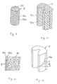
- FIGS. 5 through 8 there is shown an examplary case that the present invention is adapted to the manufacture of a gear, in which a moulding blank 8 is shown comprising an area of short fibers 8a in the core thereof where a plastic matrix is admixed with short fibers, and an outer circumferential area of longer fibers 8b where a plastic matrix is admixed with longer fibers.
- a moulding blank 8 comprising an area of short fibers 8a in the core thereof where a plastic matrix is admixed with short fibers, and an outer circumferential area of longer fibers 8b where a plastic matrix is admixed with longer fibers.
- FIGS. 9 through 12 show further embodiments of the invention, in which there is provided an outer circumferential area of longer fibers 8b in a plactic blank, which consists of a continuous fibrous layer extending rising in the upper right direction 8b i formed in the outermost circumference thereof and a continuous fibrous layer extending rising in the upper left direction 8b 2 disposed in the radially inward area thereof. More specifically, in such an embodiment, there exist a multiplicity of circumferential layers of fibers having a fiber diameter ranging from serval microns to ten microns or so disposed with a generally uniform thickness in that area of longer fibers.
- FIG. 10 shows in further detail the cross-section of an outer circumferential area of the moulding blank 8.
- the outer surface of a finished product spur gear 9 is, as typically shown in FIG. 11, formed in such a manner that there exist layers of longer fibers 9b 1 and 9b 2 which extend intercrossing with each - other.
- the product of fiber reinforced plastics would exhibit such physical properties as a maximum strength, a maximum rigidity, etc. along the orientation of fiber extension against a stress rendered thereupon, while such properties would attenuate sharply when the stress may deflect out of the orientation of fiber extension.
- an angle of rake ⁇ 1 defined between the orientation of fibers and the direction of main stresses as seen in FIG. 12 has a significant factor in the gear design.
- This angle ⁇ may be determined from such factors as the orientation of fibers involved, the dimensions of a plastic blank, and the configuration, dimensions and moulding conditions of a finished product, and the basic design concept will be presented by way of simplified models referring to FIGS. 13 through 16, as follows.
- FIG. 16 there is shown a graphic representation which shows the relationship of theoretical values observed exclusively in terms of the deformation in the mesh of the strands 15b 1 and 15b 2 with respect to a diameter d 2 as taken with a length l 2 , which is obtained from compression of the length l 1 of the moulding blank 15 having the diameter d i shown in FIG. 13.
- This graph represents the plottings with four different initial angles of inclination ⁇ 1 , and from this it is essential to determine the dimensions of blank and the arrangement of strands in consideration of the general configuration of the blank as well as the angle of inclination ⁇ 2 as required in this embodiment, because of an actual limit in the diameter d 2 of the blank which can be extended in practice without breaking or forced elongation of the strands involved, accordingly.
- FIG. 17 shows a state that when the moulding blank 15 of FIG. 13 is compressed along its axial direction with its angle of inclination of braiding a 2 turning to be generally 45 degrees, in which state there is formed a gap or clearance 15c between the strands in the outer surface of the braiding arrangment of the blank.
- FIG. 18 which is a longitudinal cross-sectional view showing part of the outer circumferential area of the blank taken along the line A-A in FIG. 17, it is seen that the area of short fibers 15a under inner pressure from the compression of the blank is urged to expand outwardly through these gaps of the strands, and then some of such short fibers would tend to shift over the outer surface of the layer of strands as typically shown in FIG.
- the extent of this gap 15c may be controlled by way of the configuration or density of braiding.
- the component of plastic matrix in the area of short fibers 15a would extrude rather than the short fibers, with the remaining content of rich short fibers turning to block the gaps 15c between the strands, there is no fear that the content of short fibers 15a would then be prevented from being extruded out of the gaps of strands to an excessive extent, accordingly.
- Such a state of entanglement of the short fibers with the area of longer fibers may bring such a marked effect that the departure between the layers of short and longer fibers can be prevented from occurring during the use of the finished product.
- FIGS. 20 through 22 show other examples of the braiding arrangement in the plastic blank which are prepared by the braiding machine
- FIG. 23 is a fragmentary cross-sectional view taken along the line C-C in FIG. 20, showing schematically the typical manner of braiding of the strands.
- a variety of braiding arrangement may be adapted in accordance with the configuration, material and dimensions of the moulding products.
- FIG. 24 is a perspective view showing an alternative construction of a plastic blank 17 in which there are provided three layers of braiding 17b i , 17b 2 and 17b 3 provided in the outer circumference of the area of short fibers. While not shown, there may be made available such a construction of a moulding blank that includes a plurality of layers of longer fibers of FIG. 9, or of the combination of such laminar structures, according to the use of such blanks.
- FIG. 25 is a longitudinal cross-sectional view showing a process of plastic formation by way of a further embodiment of the invention, in which there is shown a state of compression of a moulding blank 23 placed in the cavity of the mould halves 19, 20 and under pressure rendered by a pair of upper and lower punches 21, 22.
- This is an example of vacuum moulding process, in which there are shown provided an 0-ring 24 near the outer circumference of the mould, a nipple 25, and an annular groove 26, which are designed to provide a vacuum or reduced pressure within the cavity of the mould in cooperation with the mating surfaces of the mould halves, when there is generated a vacuum therein.
- FIG. 27 shows an improper example in which there was eventually generated a weld line 30, because of an equal speed applied to the both upper and lower urging punches, together with the effect of resistance as produced in the formation of gear teeth at the final stage of deformation.
- FIGS. 30 and 31 there is shown a further embodiment of the invention in FIGS. 30 and 31, in which there are seen provided a rod or shaft 37 in the center of a cylindrical blank 32, and a pair of compression punches 35, 36 mounted movable in mould halves 33, 34, in such a manner that the punches may force the blank to be compressed to a finished product 31 having a central opening as shown in FIG. 31.
- a cavity or opening 38 having gear teeth formation of the mould 33.
- FIGS. 32 and 33 are perspective views showing a moulding product and a plastic blank to be adapted to the process according to the invention by way of a further embodiment thereof.
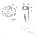
- FIG. 32 shows an example in which there is provided a pulley 39 with a central opening having a key way 39c by the employment of a forming shaft 37 defined with a ledge extending longitudinally
- FIG. 33 shows a plastic blank 40 to be moulded to the shape shown in FIG. 32.
- this blank there are shown provided a layer of short fibers 40a, a layer of longer fibers 40b, and a longitudinal groove preformed correspondingly to the key way 39c to be formed.
- FIGS. 34 and 35 are longitudinal cross-sectional views showing a further embodiment of the invention, in which there is shown a sequence of working for the formation of a spur gear 41' as shown in a perspective view of FIG. 36 and a cross-sectional view of FIG. 37 from a blank 41, respectively.
- This product gear 41' is formed to use a sleeve 49 in the center thereof.
- an upper mould half 42 an end plate 42a, a shaft 43, a lower mould half 44, an opposite end plate 44a, an opposing shaft 45, a projection 45a, a cavity defined between the both mould halves 46, an upper punch 47, a window opening 47a, a lower punch 48, another window opening 48a, a section of short fibers 41'a, and a section of longer fibers 41'b.
- FIGS. 38 through 40 are perspective views showing a still further example of a finished product in accordance with the process of the invention.
- a shaft 52 is adopted for a sleeve to be installed to a spur gear 51
- FIG. 39 showing a journal 55 having four projections 56
- FIG. 40 showing an example of a propeller product 57 having a plurality of blades 58 extending radially.
- FIG. 41 is a longitudinal cross-sectional view showing a further embodiment of the process according to the invention, in which there is produced a finished product 65 having a projection 65a shown in FIG. 42 from a cylindrical blank by using another punch working in the horizontal direction in addition to upper and lower punches 66, 67.
- a finished product 65 having a projection 65a shown in FIG. 42 from a cylindrical blank by using another punch working in the horizontal direction in addition to upper and lower punches 66, 67.
- an additional mould 63 which may be divided in the lateral direction.
- FIGS. 43 through 46 show the cases that a variety of blanks of the shape other than a cylinder.
- a rectangular blank 71 having its outer circumference covered with a layer of longer fibers 71b over a layer of short fibers 71a.
- FIG. 44 is a perspective view showing another blank of rectangular cross-section 72 having only two sides covered with a layer of longer fibers 71b i and 72b 2 over its core of short fibers 72a;
- FIG. 45 is a perspective view showing still another embodiment of blank 73 having a hexagonal cross-section and having a layer of longer fibers 73b around a core of short fibers 73a; and FIG.
- 46 is a perspective view showing a still further embodiment of blank 74 having an H-shaped cross-section and having an area of longer fibers 74b disposed discretely with respect to a core of short fibers 74a.
- a sleeve-like braiding arrangement prepared separately is adapted as the areas of longer fibers 72b 1 , 72b 2 and 74b, respectively.
- FIGS. 48 and 49 are longitudinal cross-sectional views showing a sequence of moulding procedures for a blank having a rectangular cross-section 81 to be formed to be a handle 87 as shown in FIG. 50 under the compressive force rendered by an opposed pair of compressing punches 85, 86.
- a section of short fibers 81a and a section of longer fibers 81b of the blank 81 there are shown a section of short fibers 81a and a section of longer fibers 81b of the blank 81, and a pair of mould halves 82, 83 having a cavity 84 defined between the mould halves 82, 83.
- the blanks may also be adapted to the existing enclosed forming or the matched die moulding, depending upon the shape of a moulding product.
- the fiber-containing plastic moulding blank is moulded preliminarily to a given shape prior to the enclosing mould, there is attainable the product of a homogeneous quality having less bubbles in the finished product in comparison with the products by way of the sheet moulding compound, the bulk moulding compound or the hand lay up processes. For this reason, thus-prepared product will turn out with an excellent property such as a sufficient strength, as well as a less struggling in quality of the final product.
- the processes of the invention may be adapted with the automated procedures such that the plastic matrix of the moulding blank are prepared by way of the cotinuous extrusion or drawing processes, and that the section of longer fibers is automatically formed around the outer circumference of the prepared blank by way of the filament winder, the braiding machine, etc. , and also that thus-prepared plastic blank is cut automatically to a specified dimension, it is advantageous that these moulding blanks may turn out with a less production cost,.accordingly.
- the invention it is practicable to attain a product free from defects of voids in and recesses on a moulding product, and also to provide a product allowing a variety of sleeves to be inserted therein, by making the cavity of the mould vaccum or reduced pressure before or during the moulding operation. Also, by applying a compressive force upon a lateral continued side of the blank in addition to the effect of vacuum moulding, it is possible to mould an elongated product having a complicated shape.
Landscapes
- Engineering & Computer Science (AREA)
- Mechanical Engineering (AREA)
- Chemical & Material Sciences (AREA)
- Composite Materials (AREA)
- Moulding By Coating Moulds (AREA)
- Reinforced Plastic Materials (AREA)
- Laminated Bodies (AREA)
- Casting Or Compression Moulding Of Plastics Or The Like (AREA)
Applications Claiming Priority (2)
| Application Number | Priority Date | Filing Date | Title |
|---|---|---|---|
| JP188947/84 | 1984-09-11 | ||
| JP59188947A JPS6166636A (ja) | 1984-09-11 | 1984-09-11 | 繊維強化プラスチツク成形品及びその製造方法 |
Publications (3)
| Publication Number | Publication Date |
|---|---|
| EP0177736A2 true EP0177736A2 (fr) | 1986-04-16 |
| EP0177736A3 EP0177736A3 (en) | 1987-12-16 |
| EP0177736B1 EP0177736B1 (fr) | 1990-10-31 |
Family
ID=16232696
Family Applications (1)
| Application Number | Title | Priority Date | Filing Date |
|---|---|---|---|
| EP85110844A Expired - Lifetime EP0177736B1 (fr) | 1984-09-11 | 1985-08-28 | Objet en matière plastique renforcé de fibres et procédé pour le formage d'objets |
Country Status (4)
| Country | Link |
|---|---|
| US (1) | US4677020A (fr) |
| EP (1) | EP0177736B1 (fr) |
| JP (1) | JPS6166636A (fr) |
| DE (2) | DE177736T1 (fr) |
Cited By (13)
| Publication number | Priority date | Publication date | Assignee | Title |
|---|---|---|---|---|
| WO1989010833A1 (fr) * | 1988-05-11 | 1989-11-16 | Nederlandse Organisatie Voor Toegepast-Natuurweten | Procede pour mouler des articles armes de fibres |
| WO1990000111A1 (fr) * | 1988-07-04 | 1990-01-11 | Saab-Scania Aktiebolag | Procede de production d'articles monoblocs |
| GB2266858A (en) * | 1992-05-14 | 1993-11-17 | Minster Composite Ind Limited | Panel incorporating fibre-reinforced plastics material and moulding method. |
| EP0579163A3 (fr) * | 1992-07-14 | 1994-02-23 | Composite Dev Corp | |
| US5580626A (en) * | 1992-07-14 | 1996-12-03 | Composite Development Corporation | High strength, high stiffness, curved composite member |
| EP0761418A3 (fr) * | 1995-08-30 | 1998-06-10 | The Budd Company | Procédé de moulage automatique de matière thermodurcissable et dispositif |
| US6103150A (en) * | 1998-03-11 | 2000-08-15 | The Budd Company | Molding overflow feedback method |
| US6106274A (en) * | 1995-08-30 | 2000-08-22 | The Budd Company | Molding apparatus with charge overflow |
| US6264454B1 (en) | 1998-03-11 | 2001-07-24 | The Budd Company | Wrapped SMC charge method and apparatus |
| US8024993B2 (en) | 2003-06-11 | 2011-09-27 | Campagnolo, S.R.L. | Bicycle component and method for manufacturing such a component |
| US8707823B2 (en) | 2003-06-10 | 2014-04-29 | Campagnolo S.R.L. | Bicycle component and method for making such a component |
| US8863616B2 (en) | 2006-02-14 | 2014-10-21 | Campagnolo S.R.L. | Bicycle pedal crank, intermediate product and method for manufacturing such a pedal crank |
| WO2020076984A1 (fr) * | 2018-10-09 | 2020-04-16 | Arris Composites Inc. | Procédé de moulage par intrusion d'un composite |
Families Citing this family (21)
| Publication number | Priority date | Publication date | Assignee | Title |
|---|---|---|---|---|
| NL193609C (nl) * | 1981-12-30 | 2000-04-04 | Bekaert Sa Nv | Samengestelde streng voor verwerking als granulaat in kunststofproducten en werkwijze voor het vervaardigen van een kunststofmenggranulaat. |
| JPS62152839A (ja) * | 1985-12-27 | 1987-07-07 | 積水化学工業株式会社 | 繊維強化樹脂成形品 |
| US4848745A (en) * | 1986-06-04 | 1989-07-18 | Phillips Petroleum Company | Fiber reinforced article |
| US4917938A (en) * | 1987-02-13 | 1990-04-17 | Edo Corporation | Fiber reinforced article capable of revealing damage due to surface impacts and method of making same |
| US4853868A (en) * | 1987-10-23 | 1989-08-01 | E. I. Du Pont De Nemours And Company | Method for simulating layup of prepreg materials for three-dimensional molding of composite parts |
| US5651930A (en) * | 1995-10-25 | 1997-07-29 | Zexel Usa Corporation | Composite fiber rotor vane |
| US6344160B1 (en) | 1996-09-17 | 2002-02-05 | Compcast Technologies, Llc | Method for molding composite structural plastic and objects molded thereby |
| US6103156A (en) * | 1997-06-16 | 2000-08-15 | Matthew W. Holtzberg | Method for rapid production of structural prototype plastic parts |
| CA2451336A1 (fr) * | 2001-06-22 | 2003-01-03 | Valorbec, S.E.C. | Element de renforcement non mettalique permettant de renforcer une structure et son procede de fabrication |
| WO2007098628A1 (fr) * | 2006-03-01 | 2007-09-07 | Neopreg Ag | Dispositif pour produire des pièces moulées exemptes de carotte au cours d'un procédé de moulage par transfert et d'un procédé de moulage par injection-compression |
| JP4930283B2 (ja) * | 2007-08-24 | 2012-05-16 | 株式会社豊田自動織機 | 繊維強化樹脂製歯車 |
| US9404249B2 (en) * | 2012-01-18 | 2016-08-02 | Adc Acquisition Company | Ultra light fiber placed truss |
| US20160101543A1 (en) * | 2013-12-03 | 2016-04-14 | The Boeing Company | Hybrid Laminate and Molded Composite Structures |
| JP2016203428A (ja) * | 2015-04-17 | 2016-12-08 | 日立化成株式会社 | 樹脂製回転体の製造法及び樹脂製歯車の製造法 |
| JP2016203429A (ja) * | 2015-04-17 | 2016-12-08 | 日立化成株式会社 | 樹脂製回転体の製造法及び樹脂製歯車の製造法 |
| CN110382195A (zh) * | 2017-03-01 | 2019-10-25 | 日产自动车株式会社 | 碳纤维强化树脂成形体及该碳纤维强化树脂成形体的制造方法 |
| JP6424284B1 (ja) * | 2018-03-12 | 2018-11-14 | 石川樹脂工業株式会社 | 繊維強化成形品の成形方法 |
| JP7131065B2 (ja) * | 2018-05-17 | 2022-09-06 | 株式会社安川電機 | 傘歯車部品、傘歯車、及び傘歯車部品の製造方法 |
| JP2021098280A (ja) * | 2019-12-20 | 2021-07-01 | 国立大学法人金沢大学 | 機能性部品の製造方法 |
| JP7762502B2 (ja) * | 2020-11-27 | 2025-10-30 | 住友重機械工業株式会社 | 樹脂歯車及び歯車装置 |
| JP7676901B2 (ja) * | 2021-04-16 | 2025-05-15 | 株式会社レゾナック | 樹脂製歯車の製造方法及び樹脂製歯車 |
Family Cites Families (22)
| Publication number | Priority date | Publication date | Assignee | Title |
|---|---|---|---|---|
| DE661960C (de) * | 1935-03-23 | 1938-07-01 | Siemens Schuckertwerke Akt Ges | Vorrichtung zum Herstellen von Pressstuecken |
| DE810190C (de) * | 1948-12-02 | 1951-08-06 | Voith Gmbh J M | Verfahren zur Herstellung von Drehklappen, Kurbeln o. dgl. aus Kunstharzstoff oder gummiaehnlichen Werkstoffen mit Gewebeeinlagen |
| FR1052659A (fr) * | 1952-03-19 | 1954-01-26 | Procédé de moulage de matières plastiques et, en particulier, du chlorure de vinyle par transfert et machine pour la mise en oeuvre de ce procédé | |
| GB1052773A (en) * | 1964-09-23 | 1966-12-30 | Air Logistics Corp | Method of forming reinforced three-dimensioned plastic article from plastic sheet stock and articles produced thereby |
| IT984848B (it) * | 1973-01-31 | 1974-11-20 | Restreel Srl | Metodo e relative attrezzature per la costruzione di flange ed accessori in resine rinforzate per stampaggio e flange ed accessori cosi ottenuti |
| DE2334645C3 (de) * | 1973-07-07 | 1983-04-07 | M.A.N. Maschinenfabrik Augsburg-Nürnberg AG, 8000 München | Verfahren zur Herstellung eines Trägers aus Faserverbundprofil |
| FR2289338A1 (fr) * | 1974-10-30 | 1976-05-28 | Snecma | Procede pour la preparation de materiaux composites nouveaux, materiaux obtenus et pieces finies constituees a l'aide desdits materiaux |
| US4097626A (en) * | 1976-06-07 | 1978-06-27 | Grafalloy Corporation | Construction for a fiber reinforced shaft |
| JPS63430Y2 (fr) * | 1978-05-04 | 1988-01-07 | ||
| JPS6046599B2 (ja) * | 1978-07-25 | 1985-10-16 | 東レ株式会社 | スピ−カ−コ−ン |
| US4320160A (en) * | 1979-08-21 | 1982-03-16 | Toray Industries, Inc. | Fabric structure for fiber reinforced plastics |
| JPS56115216A (en) * | 1980-01-24 | 1981-09-10 | Hitachi Chem Co Ltd | Prepreg material and manufacture thereof |
| JPS576154A (en) * | 1980-06-09 | 1982-01-13 | Mitsubishi Rayon Co Ltd | Fiber tempered plastic gear and its manufacturing method |
| JPS5812859A (ja) * | 1981-07-17 | 1983-01-25 | Mitsuwa Seiki Co Ltd | トレ−ラ制御用リレ−バルブ |
| JPS5818225A (ja) * | 1981-07-28 | 1983-02-02 | Nissan Motor Co Ltd | 繊維強化プラスチツク製ロ−ドホイ−ルの製造方法 |
| US4420523A (en) * | 1982-02-01 | 1983-12-13 | N. V. Bekaert S.A. | Energy-absorbing laminate |
| US4451041A (en) * | 1982-02-05 | 1984-05-29 | Mizuno Corporation | Golf club head and a method for manufacturing the same |
| US4581190A (en) * | 1982-04-23 | 1986-04-08 | Nippon Gakki Seizo Kabushiki Kaisha | Process for producing a wood-type golf club head |
| JPS58214085A (ja) * | 1982-06-07 | 1983-12-13 | 積水化学工業株式会社 | 繊維強化樹脂製フランジ及びその製造方法 |
| US4495231A (en) * | 1982-09-29 | 1985-01-22 | Avco Corporation | Fiber composite |
| US4469730A (en) * | 1982-12-30 | 1984-09-04 | The Boeing Company | Composite base structure and end fitting joint and method |
| US4581263A (en) * | 1984-08-27 | 1986-04-08 | Fiber Materials, Inc. | Graphite fiber mold |
-
1984
- 1984-09-11 JP JP59188947A patent/JPS6166636A/ja active Granted
-
1985
- 1985-08-13 US US06/765,198 patent/US4677020A/en not_active Expired - Fee Related
- 1985-08-28 EP EP85110844A patent/EP0177736B1/fr not_active Expired - Lifetime
- 1985-08-28 DE DE198585110844T patent/DE177736T1/de active Pending
- 1985-08-28 DE DE8585110844T patent/DE3580334D1/de not_active Expired - Lifetime
Cited By (24)
| Publication number | Priority date | Publication date | Assignee | Title |
|---|---|---|---|---|
| WO1989010833A1 (fr) * | 1988-05-11 | 1989-11-16 | Nederlandse Organisatie Voor Toegepast-Natuurweten | Procede pour mouler des articles armes de fibres |
| WO1990000111A1 (fr) * | 1988-07-04 | 1990-01-11 | Saab-Scania Aktiebolag | Procede de production d'articles monoblocs |
| GB2266858A (en) * | 1992-05-14 | 1993-11-17 | Minster Composite Ind Limited | Panel incorporating fibre-reinforced plastics material and moulding method. |
| GB2266858B (en) * | 1992-05-14 | 1996-05-08 | Minster Composite Ind Limited | Panel incorporating fibre-reinforced plastics material |
| EP0579163A3 (fr) * | 1992-07-14 | 1994-02-23 | Composite Dev Corp | |
| US5437899A (en) * | 1992-07-14 | 1995-08-01 | Composite Development Corporation | Structural element formed of a fiber reinforced thermoplastic material and method of manufacture |
| US5540870A (en) * | 1992-07-14 | 1996-07-30 | Composite Development Corporation | Structural element formed of a fiber reinforced thermoplastic material and method of manufacture |
| US5580626A (en) * | 1992-07-14 | 1996-12-03 | Composite Development Corporation | High strength, high stiffness, curved composite member |
| US6106274A (en) * | 1995-08-30 | 2000-08-22 | The Budd Company | Molding apparatus with charge overflow |
| EP0761418A3 (fr) * | 1995-08-30 | 1998-06-10 | The Budd Company | Procédé de moulage automatique de matière thermodurcissable et dispositif |
| US5902613A (en) * | 1995-08-30 | 1999-05-11 | The Budd Company | Automated thermoset molding apparatus |
| US6264454B1 (en) | 1998-03-11 | 2001-07-24 | The Budd Company | Wrapped SMC charge method and apparatus |
| US6103150A (en) * | 1998-03-11 | 2000-08-15 | The Budd Company | Molding overflow feedback method |
| US8707823B2 (en) | 2003-06-10 | 2014-04-29 | Campagnolo S.R.L. | Bicycle component and method for making such a component |
| US8024993B2 (en) | 2003-06-11 | 2011-09-27 | Campagnolo, S.R.L. | Bicycle component and method for manufacturing such a component |
| US10105916B2 (en) | 2003-06-11 | 2018-10-23 | Campagnolo S.R.L. | Bicycle component and method for manufacturing such a component |
| US8863616B2 (en) | 2006-02-14 | 2014-10-21 | Campagnolo S.R.L. | Bicycle pedal crank, intermediate product and method for manufacturing such a pedal crank |
| WO2020076984A1 (fr) * | 2018-10-09 | 2020-04-16 | Arris Composites Inc. | Procédé de moulage par intrusion d'un composite |
| US10946595B2 (en) | 2018-10-09 | 2021-03-16 | Arris Composites Inc. | Method for composite flow molding |
| KR20210072799A (ko) * | 2018-10-09 | 2021-06-17 | 애리스 컴포지트 아이엔씨. | 복합재 유동 몰딩을 위한 방법 |
| JP2022511611A (ja) * | 2018-10-09 | 2022-02-01 | アリス・コンポジッツ・インコーポレイテッド | 複合流成形のための方法 |
| US11426956B2 (en) | 2018-10-09 | 2022-08-30 | Arris Composites Inc. | Method for composite flow molding |
| KR102445089B1 (ko) | 2018-10-09 | 2022-09-21 | 애리스 컴포지트 아이엔씨. | 복합재 유동 몰딩을 위한 방법 |
| US11623370B2 (en) | 2018-10-09 | 2023-04-11 | Arris Composites Inc. | Method for composite flow molding |
Also Published As
| Publication number | Publication date |
|---|---|
| DE3580334D1 (de) | 1990-12-06 |
| EP0177736A3 (en) | 1987-12-16 |
| US4677020A (en) | 1987-06-30 |
| DE177736T1 (de) | 1986-09-04 |
| EP0177736B1 (fr) | 1990-10-31 |
| JPS6166636A (ja) | 1986-04-05 |
| JPH0570568B2 (fr) | 1993-10-05 |
Similar Documents
| Publication | Publication Date | Title |
|---|---|---|
| US4677020A (en) | Fiber reinforced plastic product and method of forming products | |
| JP4235469B2 (ja) | 繊維複合構造の部材を製造する方法 | |
| US4863330A (en) | Composite fastener and method of manufacture | |
| DE69231121T2 (de) | Verfahren zur Herstellung geformter Erzeugnisse aus verstärkten thermoplastischen Folien | |
| CA1286582C (fr) | Methode et dispositif pour la mise en forme de materiaux ondules par recoursa des noyaux magnetiques a memoire | |
| US5681513A (en) | Method for fabricating composite structures using continuous press forming | |
| CA2121923A1 (fr) | Methode pour l'obtention d'un engrenage | |
| KR100558389B1 (ko) | 사출 성형용 삽입 파이프, 삽입 파이프 처리 방법 및,성형 제품 | |
| US20140311324A1 (en) | Conformable Braid | |
| WO2012076154A1 (fr) | Façonnage d'un pré-imprégné fibreux | |
| US5066442A (en) | Method of producing a composite article | |
| JP2610284B2 (ja) | 回転ねじ機械のロータ、回転ねじ機械、及びロータの製造方法 | |
| US6047580A (en) | Making hydropress formblocks and dies utilizing stereolithography and liquid molding compounds | |
| JPH11108027A (ja) | Uボルトの製法 | |
| CA1043066A (fr) | Fibre de verre | |
| US3979493A (en) | Method for producing glass fiber reinforcing members | |
| KR100773307B1 (ko) | 복수의 공극을 갖는 재료를 제조하기 위한 예비 성형체 및그 제조 방법 | |
| JP2773261B2 (ja) | 繊維強化熱可塑性樹脂成形体の製造方法 | |
| JPS63221035A (ja) | 異形断面を有する繊維強化合成樹脂製配筋の製造方法 | |
| JPS63219746A (ja) | 異形断面を有する繊維強化合成樹脂製配筋及びその製造方法 | |
| EP4559664A2 (fr) | Procédé de fabrication sans outil d'une structure creuse | |
| RU2088405C1 (ru) | Фильера для формования профильных изделий из полимерных композиционных материалов | |
| JPS5863418A (ja) | 押出成形による合成樹脂製ラツクギヤの製造方法とその製造装置 | |
| DE10158663C1 (de) | Verfahren zur Erzeugung einer Leitung aus Kunststoff mit einem Abzweig und Werkzeug zur Fertigung einer einen Abzweig aufweisenden Leitung | |
| WO1997003813A1 (fr) | Produit renforce fabrique a partir d'un renforcement et d'un plastique matriciel, et procede de fabrication |
Legal Events
| Date | Code | Title | Description |
|---|---|---|---|
| PUAI | Public reference made under article 153(3) epc to a published international application that has entered the european phase |
Free format text: ORIGINAL CODE: 0009012 |
|
| 17P | Request for examination filed |
Effective date: 19850925 |
|
| AK | Designated contracting states |
Kind code of ref document: A2 Designated state(s): BE DE FR GB SE |
|
| EL | Fr: translation of claims filed | ||
| DET | De: translation of patent claims | ||
| PUAL | Search report despatched |
Free format text: ORIGINAL CODE: 0009013 |
|
| AK | Designated contracting states |
Kind code of ref document: A3 Designated state(s): BE DE FR GB SE |
|
| 17Q | First examination report despatched |
Effective date: 19890428 |
|
| GRAA | (expected) grant |
Free format text: ORIGINAL CODE: 0009210 |
|
| AK | Designated contracting states |
Kind code of ref document: B1 Designated state(s): BE DE FR GB SE |
|
| REF | Corresponds to: |
Ref document number: 3580334 Country of ref document: DE Date of ref document: 19901206 |
|
| ET | Fr: translation filed | ||
| PLBE | No opposition filed within time limit |
Free format text: ORIGINAL CODE: 0009261 |
|
| STAA | Information on the status of an ep patent application or granted ep patent |
Free format text: STATUS: NO OPPOSITION FILED WITHIN TIME LIMIT |
|
| 26N | No opposition filed | ||
| REG | Reference to a national code |
Ref country code: GB Ref legal event code: 746 |
|
| REG | Reference to a national code |
Ref country code: FR Ref legal event code: DL |
|
| EAL | Se: european patent in force in sweden |
Ref document number: 85110844.9 |
|
| PGFP | Annual fee paid to national office [announced via postgrant information from national office to epo] |
Ref country code: FR Payment date: 19960809 Year of fee payment: 12 |
|
| PGFP | Annual fee paid to national office [announced via postgrant information from national office to epo] |
Ref country code: SE Payment date: 19960815 Year of fee payment: 12 |
|
| PGFP | Annual fee paid to national office [announced via postgrant information from national office to epo] |
Ref country code: GB Payment date: 19960819 Year of fee payment: 12 |
|
| PGFP | Annual fee paid to national office [announced via postgrant information from national office to epo] |
Ref country code: DE Payment date: 19960906 Year of fee payment: 12 |
|
| PGFP | Annual fee paid to national office [announced via postgrant information from national office to epo] |
Ref country code: BE Payment date: 19961009 Year of fee payment: 12 |
|
| PG25 | Lapsed in a contracting state [announced via postgrant information from national office to epo] |
Ref country code: GB Free format text: LAPSE BECAUSE OF NON-PAYMENT OF DUE FEES Effective date: 19970828 |
|
| PG25 | Lapsed in a contracting state [announced via postgrant information from national office to epo] |
Ref country code: SE Free format text: LAPSE BECAUSE OF NON-PAYMENT OF DUE FEES Effective date: 19970829 |
|
| PG25 | Lapsed in a contracting state [announced via postgrant information from national office to epo] |
Ref country code: BE Free format text: LAPSE BECAUSE OF NON-PAYMENT OF DUE FEES Effective date: 19970831 |
|
| BERE | Be: lapsed |
Owner name: MITSUBISHI JUKOGYO K.K. Effective date: 19970831 |
|
| GBPC | Gb: european patent ceased through non-payment of renewal fee |
Effective date: 19970828 |
|
| PG25 | Lapsed in a contracting state [announced via postgrant information from national office to epo] |
Ref country code: FR Free format text: LAPSE BECAUSE OF NON-PAYMENT OF DUE FEES Effective date: 19980430 |
|
| PG25 | Lapsed in a contracting state [announced via postgrant information from national office to epo] |
Ref country code: DE Free format text: LAPSE BECAUSE OF NON-PAYMENT OF DUE FEES Effective date: 19980501 |
|
| EUG | Se: european patent has lapsed |
Ref document number: 85110844.9 |
|
| REG | Reference to a national code |
Ref country code: FR Ref legal event code: ST |