EP0177751A2 - Echangeur de chaleur gaz-liquide ou gaz-gaz - Google Patents
Echangeur de chaleur gaz-liquide ou gaz-gaz Download PDFInfo
- Publication number
- EP0177751A2 EP0177751A2 EP85111134A EP85111134A EP0177751A2 EP 0177751 A2 EP0177751 A2 EP 0177751A2 EP 85111134 A EP85111134 A EP 85111134A EP 85111134 A EP85111134 A EP 85111134A EP 0177751 A2 EP0177751 A2 EP 0177751A2
- Authority
- EP
- European Patent Office
- Prior art keywords
- heat exchanger
- gas
- layers
- heat
- layer
- Prior art date
- Legal status (The legal status is an assumption and is not a legal conclusion. Google has not performed a legal analysis and makes no representation as to the accuracy of the status listed.)
- Granted
Links
- 239000007788 liquid Substances 0.000 title claims description 12
- 238000000034 method Methods 0.000 claims description 2
- 239000010410 layer Substances 0.000 description 37
- 241000446313 Lamella Species 0.000 description 6
- XLYOFNOQVPJJNP-UHFFFAOYSA-N water Substances O XLYOFNOQVPJJNP-UHFFFAOYSA-N 0.000 description 4
- 239000000463 material Substances 0.000 description 3
- 230000007547 defect Effects 0.000 description 2
- 239000002346 layers by function Substances 0.000 description 2
- 238000010276 construction Methods 0.000 description 1
- 238000012423 maintenance Methods 0.000 description 1
Images

Classifications
-
- F—MECHANICAL ENGINEERING; LIGHTING; HEATING; WEAPONS; BLASTING
- F28—HEAT EXCHANGE IN GENERAL
- F28F—DETAILS OF HEAT-EXCHANGE AND HEAT-TRANSFER APPARATUS, OF GENERAL APPLICATION
- F28F27/00—Control arrangements or safety devices specially adapted for heat-exchange or heat-transfer apparatus
- F28F27/02—Control arrangements or safety devices specially adapted for heat-exchange or heat-transfer apparatus for controlling the distribution of heat-exchange media between different channels
-
- F—MECHANICAL ENGINEERING; LIGHTING; HEATING; WEAPONS; BLASTING
- F28—HEAT EXCHANGE IN GENERAL
- F28D—HEAT-EXCHANGE APPARATUS, NOT PROVIDED FOR IN ANOTHER SUBCLASS, IN WHICH THE HEAT-EXCHANGE MEDIA DO NOT COME INTO DIRECT CONTACT
- F28D7/00—Heat-exchange apparatus having stationary tubular conduit assemblies for both heat-exchange media, the media being in contact with different sides of a conduit wall
- F28D7/08—Heat-exchange apparatus having stationary tubular conduit assemblies for both heat-exchange media, the media being in contact with different sides of a conduit wall the conduits being otherwise bent, e.g. in a serpentine or zig-zag
- F28D7/082—Heat-exchange apparatus having stationary tubular conduit assemblies for both heat-exchange media, the media being in contact with different sides of a conduit wall the conduits being otherwise bent, e.g. in a serpentine or zig-zag with serpentine or zig-zag configuration
- F28D7/085—Heat-exchange apparatus having stationary tubular conduit assemblies for both heat-exchange media, the media being in contact with different sides of a conduit wall the conduits being otherwise bent, e.g. in a serpentine or zig-zag with serpentine or zig-zag configuration in the form of parallel conduits coupled by bent portions
-
- F—MECHANICAL ENGINEERING; LIGHTING; HEATING; WEAPONS; BLASTING
- F28—HEAT EXCHANGE IN GENERAL
- F28F—DETAILS OF HEAT-EXCHANGE AND HEAT-TRANSFER APPARATUS, OF GENERAL APPLICATION
- F28F1/00—Tubular elements; Assemblies of tubular elements
- F28F1/10—Tubular elements and assemblies thereof with means for increasing heat-transfer area, e.g. with fins, with projections, with recesses
- F28F1/12—Tubular elements and assemblies thereof with means for increasing heat-transfer area, e.g. with fins, with projections, with recesses the means being only outside the tubular element
- F28F1/24—Tubular elements and assemblies thereof with means for increasing heat-transfer area, e.g. with fins, with projections, with recesses the means being only outside the tubular element and extending transversely
- F28F1/32—Tubular elements and assemblies thereof with means for increasing heat-transfer area, e.g. with fins, with projections, with recesses the means being only outside the tubular element and extending transversely the means having portions engaging further tubular elements
-
- F—MECHANICAL ENGINEERING; LIGHTING; HEATING; WEAPONS; BLASTING
- F28—HEAT EXCHANGE IN GENERAL
- F28F—DETAILS OF HEAT-EXCHANGE AND HEAT-TRANSFER APPARATUS, OF GENERAL APPLICATION
- F28F9/00—Casings; Header boxes; Auxiliary supports for elements; Auxiliary members within casings
- F28F9/26—Arrangements for connecting different sections of heat-exchange elements, e.g. of radiators
Definitions
- the invention relates to a gas / liquid or gas / gas heat exchanger with layers, each having a plurality of mutually parallel one-piece heat-conducting fins, which transfer the heat from one medium to a second in a countercurrent process.
- Air / water and air / air heat exchangers of various types are known. These have plates or lamellae and / or pipes, the two streams of air and / or water being conducted through lines or channels and, in the meantime, one of the two media giving off its heat to the other medium. The highest degree of temperature exchange is achieved with countercurrent heat exchangers.
- the object of the invention is to provide a heat exchanger which has a very high degree of temperature exchange, is easy to repair and can be assembled and disassembled without great effort.
- the heat exchanger is divided into heat exchanger layers, each of which forms a complete heat exchanger which guides both media and has a group of parallel heat-conducting fins, which are insoluble and are at the same height, that each layer is parallel to the other layers with their two inlets and outlets are separately connected to the main inlet and outlet lines of the entire heat exchanger, and that the layers are detachably connected to adjacent layers.
- Such a heat exchanger is divided into individual, in the countercurrent principle heat exchanging and functional layer modules.
- the required heat exchanger length can be selected for any heat exchange task, efficiently manufactured in modules and assembled on site at the application site. Transport and assembly are extremely simple and maintenance is not labor intensive. In the event of a defect, only the relevant heat exchanger layer needs to be repaired or replaced.
- the heat exchanger Since the heat exchanger is divided into many individual layers, it can be used for heat exchange or for required temperature exchange degree required exchanger surface in front of each other - that is, in countercurrent - are arranged.
- a block construction - as previously known - can be manufactured but is not practical. It is particularly advantageous if the height of each slat is a multiple of the distance between the slats. This means that the heat transfer takes place essentially over the fins and not over the walls separating the medium channels.
- the lamella thickness is dimensioned in relation to the lamella material in such a way that low-energy loss heat conduction occurs.
- a separating surface can be attached between the individual layers of the heat exchanger, which separates the medium flow of one layer from the medium flow of the adjacent layer. This means that cross turbulence is prevented and pressure losses are particularly low. Furthermore, the condensate that forms in one layer cannot run into other layers and can increasingly generate pressure losses there.
- the fins extend into both media paths of different warmth, since it is ensured, in particular when the fins are narrow, that the heat transfer occurs essentially only via the fins and thus exergy losses are particularly low.
- the heat flow from one medium to another is essentially only via the fins.
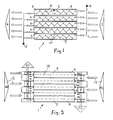
- the gas / liquid, in particular air / water, heat exchanger shown in FIG. 1 is flowed through from right to left by gas or air and in the counterflow of liquid or water. It is divided into five layers 2, which form functional modules that each form a complete heat exchanger. Each layer 2 is connected separately at the inlet 3 and outlet 4 of the gas as well as at the inlet 5 and outlet 6 of the liquid, so that the entire gas flow and the entire liquid flow are divided into individual flows, a flow of both media being provided for each layer is and behind the heat exchanger these flows are again combined into a total flow. While the gas streams 7 flow straight through the individual layers, the liquid flows back and forth in a pipe coil 8 in each layer 2, whereby the liquid stream crosses and flows against the air stream.
- each layer 2 numerous fins 9 are fastened to the tubes 8 parallel to the gas flow, the fins 9 being perpendicular to the regions of the tubes 8 which run through the family of fins.
- the lamella thickness is dimensioned in relation to the lamella material in such a way that low-energy loss heat conduction occurs.
- a separating surface 10 which separates the gas paths of each layer.
- each layer is connected at the beginning and end of the layer via a valve 11 to the inlet 5 and outlet line 6, respectively, so that the layers can be vented when they are put into operation for the first time and after closing two valves 11 each layer is easily taken out of operation, checked , can be cleaned or dismantled on the liquid side without disassembly.
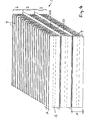
- the gas / gas, in particular air / air, heat exchanger shown in FIGS. 3 and 4 can have exhaust gas (exhaust gas) or outside air 12 flowing through them from left to right and a second gas stream 13 flowing from right to left.
- the heat exchanger is divided into five individual, functional layer modules 2, each module having finned heat-conducting surfaces in order to extract and transfer heat from the gas flows flowing in countercurrent.
- Each layer 2 has a separating plane 14 in the center, on which the slats 9 are fastened at right angles and parallel to one another. The two gas streams are separated from one another by these levels 14, so that apart from the outer areas, i.e. 4 the upper and lower region, the gas flows each flow through two adjacent layers 2.
- Each layer 2 is connected separately from the other layers to the inlet and outlet of both gas streams, so that, as in the first exemplary embodiment, both media streams are divided and flow through each layer with partial streams and are then led to the two outlets without leading to one to get to the next layer.
- the lamellae 9 thus extend into the paths of two different media, and the lamellae 9 are so close together that a heat flow essentially only via the slats.
- the height of the slats H is a multiple of the distance A from each other.
- the lamella thickness is dimensioned in relation to the lamella material in such a way that low-energy loss heat conduction occurs.
- Parallel separating surfaces 10 are arranged between the individual module layers 2 of the heat exchanger, and the same medium flow flows around them on both sides.
- each layer 2 is releasably attached to the adjacent layer or layers, so that they can be easily replaced and assembled and removed.
- Both heat exchangers can be used not only in the horizontal position shown in the figures, but also in other positions, in particular in a vertical position.
- the degree of temperature exchange is 75 to 90%.
Landscapes
- Engineering & Computer Science (AREA)
- Physics & Mathematics (AREA)
- Thermal Sciences (AREA)
- Mechanical Engineering (AREA)
- General Engineering & Computer Science (AREA)
- Geometry (AREA)
- Heat-Exchange Devices With Radiators And Conduit Assemblies (AREA)
- Gas Separation By Absorption (AREA)
Priority Applications (1)
| Application Number | Priority Date | Filing Date | Title |
|---|---|---|---|
| AT85111134T ATE46032T1 (de) | 1984-09-13 | 1985-09-04 | Gas/fluessigkeit- oder gas/gas-waermeaustauscher. |
Applications Claiming Priority (2)
| Application Number | Priority Date | Filing Date | Title |
|---|---|---|---|
| DE3433598 | 1984-09-13 | ||
| DE19843433598 DE3433598A1 (de) | 1984-09-13 | 1984-09-13 | Verfahren zur praktischen anwendung des gegenstromprinzips fuer waermeaustauscher, luft/wasser, luft/luft oder sinngemaess fuer andere medien |
Publications (3)
| Publication Number | Publication Date |
|---|---|
| EP0177751A2 true EP0177751A2 (fr) | 1986-04-16 |
| EP0177751A3 EP0177751A3 (en) | 1986-10-22 |
| EP0177751B1 EP0177751B1 (fr) | 1989-08-30 |
Family
ID=6245290
Family Applications (1)
| Application Number | Title | Priority Date | Filing Date |
|---|---|---|---|
| EP85111134A Expired EP0177751B1 (fr) | 1984-09-13 | 1985-09-04 | Echangeur de chaleur gaz-liquide ou gaz-gaz |
Country Status (5)
| Country | Link |
|---|---|
| US (1) | US4738309A (fr) |
| EP (1) | EP0177751B1 (fr) |
| AT (1) | ATE46032T1 (fr) |
| DD (1) | DD239655A5 (fr) |
| DE (2) | DE3433598A1 (fr) |
Cited By (4)
| Publication number | Priority date | Publication date | Assignee | Title |
|---|---|---|---|---|
| DE4408087A1 (de) * | 1994-03-10 | 1995-09-14 | Schilling Heinz Kg | Verfahren zum Betrieb einer Wärmeaustauscheranlage, für rekuperativen Wärmeaustausch zwischen flüssigen und gasförmigen Medien im Gegenstromprinzip, mit mehreren, innerhalb des Wärmeaustauschers unterschiedlichen Wärmekapazitätenstromverhältnissen |
| DE19546276A1 (de) * | 1995-12-12 | 1997-06-19 | Schilling Heinz Kg | Verfahren und Vorrichtung zur betriebssicheren Funktion von Wärmeaustauschern mit mehreren parallelen flüssigkeitsdurchströmten Bauteilen zur Wärmeübertragung zwischen flüssigen und flüssig/gasförmigen Medien |
| EP0838649A2 (fr) | 1996-10-28 | 1998-04-29 | Heinz Schilling KG | Echangeur de chaleur avec modules de tubes à ailettes et partitions horizontales, pour échange de chaleur entre fluides gazeux ou liquides |
| WO2004068052A1 (fr) | 2003-01-31 | 2004-08-12 | Heinz Schilling Kg | Echangeur de chaleur a air et a eau a parcours partiels de l'eau |
Families Citing this family (30)
| Publication number | Priority date | Publication date | Assignee | Title |
|---|---|---|---|---|
| GB2202932B (en) * | 1987-03-26 | 1991-05-15 | Coppermill Limited | Heat regenerators |
| DE3916779C2 (de) * | 1988-09-30 | 1998-04-09 | Valeo Sistemi Termici S P A | Wärmetauscher, insbesondere für die Heizungsanlage eines Kraftfahrzeuges |
| DK171423B1 (da) * | 1993-03-26 | 1996-10-21 | Topsoe Haldor As | Spildevarmekedel |
| FR2767380B1 (fr) * | 1997-08-18 | 1999-09-24 | Gec Alsthom Stein Ind | Dispositif d'echange thermique pour une chaudiere a lit fluidise circulant |
| US6640543B1 (en) * | 2001-09-21 | 2003-11-04 | Western Washington University | Internal combustion engine having variable displacement |
| US7454956B1 (en) * | 2005-09-22 | 2008-11-25 | Lopresti William J | Heat exchanger leak detection using mass gas flow metering |
| US9618485B2 (en) * | 2007-11-12 | 2017-04-11 | Agilent Technology, Inc. | HPLC-system with variable flow rate |
| US8540012B2 (en) * | 2008-06-13 | 2013-09-24 | Lockheed Martin Corporation | Heat exchanger |
| JP2012533722A (ja) | 2009-07-16 | 2012-12-27 | ロッキード マーティン コーポレーション | 熱交換器用螺旋管束集成装置 |
| KR20150040376A (ko) | 2009-07-17 | 2015-04-14 | 록히드 마틴 코포레이션 | 열 교환기 및 제작 방법 |
| US9777971B2 (en) * | 2009-10-06 | 2017-10-03 | Lockheed Martin Corporation | Modular heat exchanger |
| US20110127022A1 (en) * | 2009-12-01 | 2011-06-02 | Lockheed Martin Corporation | Heat Exchanger Comprising Wave-shaped Fins |
| US20110277473A1 (en) * | 2010-05-14 | 2011-11-17 | Geoffrey Courtright | Thermal Energy Transfer System |
| US9388798B2 (en) | 2010-10-01 | 2016-07-12 | Lockheed Martin Corporation | Modular heat-exchange apparatus |
| US9670911B2 (en) | 2010-10-01 | 2017-06-06 | Lockheed Martin Corporation | Manifolding arrangement for a modular heat-exchange apparatus |
| JP5163763B2 (ja) * | 2011-02-23 | 2013-03-13 | ダイキン工業株式会社 | 空気調和機用熱交換器 |
| WO2013138492A1 (fr) * | 2012-03-13 | 2013-09-19 | Blissfield Manufacturing Company | Échangeur de chaleur du type emboîté |
| US9631880B2 (en) * | 2012-04-10 | 2017-04-25 | Lenovo Enterprise Solutions (Singapore) Pte. Ltd. | Process for optimizing a heat exchanger configuration |
| DE102012108109B4 (de) * | 2012-08-31 | 2014-04-10 | Rittal Gmbh & Co. Kg | Wärmetauscher für die Schaltschrankkühlung und eine entsprechende Kühlanordnung |
| DE102013003905B4 (de) | 2013-03-08 | 2020-01-23 | Simon Benzler | Modulwärmeübertrager in lüftungstechnischen Geräten |
| GB2521430A (en) * | 2013-12-19 | 2015-06-24 | Ibm | Device and method for converting heat into mechanical energy |
| US10443945B2 (en) * | 2014-03-12 | 2019-10-15 | Lennox Industries Inc. | Adjustable multi-pass heat exchanger |
| WO2015143348A1 (fr) | 2014-03-21 | 2015-09-24 | Veotec Americas LLC | Systèmes et procédés de séparateur d'admission d'air |
| US10203171B2 (en) * | 2014-04-18 | 2019-02-12 | Lennox Industries Inc. | Adjustable multi-pass heat exchanger system |
| US20240108148A1 (en) * | 2014-05-09 | 2024-04-04 | Sleepme Inc. | Devices for Enhancing the Thermal Efficiency and Customizing the Shapes of Cooling or Heating Zones in a Bed |
| FR3028025B1 (fr) * | 2014-10-30 | 2016-11-04 | Nexter Systems | Dispositif de camouflage thermique et vehicule comportant un tel dispositif |
| US20180094867A1 (en) * | 2016-09-30 | 2018-04-05 | Gilles Savard | Air-liquid heat exchanger |
| US20180224218A1 (en) * | 2017-02-07 | 2018-08-09 | Johnson Controls Technology Company | Heat exchanger coil array and method for assembling same |
| US10895405B2 (en) * | 2018-09-25 | 2021-01-19 | Rheem Manufacturing Company | Tankless water heater apparatus, system, and methods |
| JP6741820B1 (ja) * | 2019-04-12 | 2020-08-19 | 株式会社神戸製鋼所 | 気化装置の置き換え方法 |
Family Cites Families (29)
| Publication number | Priority date | Publication date | Assignee | Title |
|---|---|---|---|---|
| DE43378C (de) * | F. FEHR in München, Lindwurmstrafse 21 III. links | Dampf-Wasserofen | ||
| US1123765A (en) * | 1912-02-10 | 1915-01-05 | James J Lawler | Water-heater. |
| US1901090A (en) * | 1929-11-30 | 1933-03-14 | Siemens Ag | Multiple heat exchange coil |
| US1926719A (en) * | 1931-07-08 | 1933-09-12 | American Eng Co Ltd | Refrigerating apparatus |
| US1899629A (en) * | 1931-10-26 | 1933-02-28 | American Blower Corp | Steel pipe and fin heater |
| US2237239A (en) * | 1935-02-26 | 1941-04-01 | Fedders Mfg Co Inc | Refrigeration apparatus |
| US2044069A (en) * | 1935-07-25 | 1936-06-16 | Gen Refrigeration Corp | Finned evaporator |
| US2217410A (en) * | 1938-02-17 | 1940-10-08 | Gen Electric | Heat exchange apparatus |
| US2354131A (en) * | 1938-03-19 | 1944-07-18 | Lul Products Inc | Refrigerating apparatus |
| US2532608A (en) * | 1946-05-07 | 1950-12-05 | Dalin David | Method of heating |
| US2505790A (en) * | 1946-07-24 | 1950-05-02 | Perfex Corp | Combination radiator and oil cooler |
| US2512560A (en) * | 1946-08-07 | 1950-06-20 | Young Radiator Co | Radiator header construction |
| FR1311571A (fr) * | 1960-12-29 | 1962-12-07 | Cie Europ Des Materiels Thermi | échangeur de chaleur à serpentins |
| FR1389311A (fr) * | 1964-04-13 | 1965-02-12 | Système de tubes à ailettes, notamment pour préchauffeurs d'eau d'alimentation de chaudières à vapeur | |
| FR2008887B1 (fr) * | 1968-05-20 | 1973-12-07 | Kobe Steel Ltd | |
| DE1933688A1 (de) * | 1969-07-03 | 1971-01-21 | Schubert Maschf Geb | Lamellenheizkoerper |
| AT313855B (de) * | 1971-01-13 | 1974-03-11 | Buss Ag | Einrichtung zur Durchführung des Wärmeaustausches zwischen einem Wärmeträgermedium und einem Drehrohr |
| DE7625179U1 (de) * | 1976-08-11 | 1978-02-02 | Mollerus, Josef, Dipl.-Ing., 7758 Meersburg | Lueftungskanal mit integrierter rekuperativer waerme- oder kaelterueckgewinnung |
| US4197625A (en) * | 1978-02-15 | 1980-04-15 | Carrier Corporation | Plate fin coil assembly |
| SE7808367L (sv) * | 1978-08-03 | 1980-02-04 | Ostbo John D B | Anordning vid vermevexlare |
| FR2441820A1 (fr) * | 1978-11-20 | 1980-06-13 | Chausson Usines Sa | Echangeur refroidisseur industriel servant au refroidissement de l'air ou d'un autre gaz |
| DE2906837A1 (de) * | 1979-02-22 | 1980-09-04 | Fsl Fenster System Lueftung | Kontinuierlicher waermeaustauscher fuer gasfoermiges fluidum |
| DE3011011C2 (de) * | 1979-03-22 | 1983-06-01 | Hitachi, Ltd., Tokyo | Plattenwärmetauscher mit in einem Stapel angeordneten rechteckigen Platten |
| JPS5674592A (en) * | 1979-11-21 | 1981-06-20 | Toshimi Kuma | Opposing current type heat exchanger |
| DE3044135C2 (de) * | 1980-11-24 | 1983-01-27 | Siemens AG, 1000 Berlin und 8000 München | Luft-Luft-Wärmetauscher |
| DE8032917U1 (de) * | 1980-12-11 | 1981-04-02 | Klix, Uwe, 7210 Rottweil | Waermetauscher |
| CH649625A5 (de) * | 1982-02-08 | 1985-05-31 | Paul Stuber | Verwendung von stegdoppelplatten zum fuehren von frisch- und abluft in einem waermetauscher. |
| DE3328229C2 (de) * | 1983-08-04 | 1985-10-10 | Möbius & Ruppert, 8520 Erlangen | Wärmetauscher |
| GR1000349B (el) * | 1989-07-21 | 1992-06-25 | Bat Cigarettenfab Gmbh | Φίλτρο Σιγαρέττου. |
-
1984
- 1984-09-13 DE DE19843433598 patent/DE3433598A1/de not_active Withdrawn
-
1985
- 1985-09-04 DE DE8585111134T patent/DE3572723D1/de not_active Expired
- 1985-09-04 EP EP85111134A patent/EP0177751B1/fr not_active Expired
- 1985-09-04 AT AT85111134T patent/ATE46032T1/de not_active IP Right Cessation
- 1985-09-12 DD DD85280569A patent/DD239655A5/de not_active IP Right Cessation
- 1985-09-13 US US06/775,849 patent/US4738309A/en not_active Expired - Lifetime
Cited By (6)
| Publication number | Priority date | Publication date | Assignee | Title |
|---|---|---|---|---|
| DE4408087A1 (de) * | 1994-03-10 | 1995-09-14 | Schilling Heinz Kg | Verfahren zum Betrieb einer Wärmeaustauscheranlage, für rekuperativen Wärmeaustausch zwischen flüssigen und gasförmigen Medien im Gegenstromprinzip, mit mehreren, innerhalb des Wärmeaustauschers unterschiedlichen Wärmekapazitätenstromverhältnissen |
| DE19546276A1 (de) * | 1995-12-12 | 1997-06-19 | Schilling Heinz Kg | Verfahren und Vorrichtung zur betriebssicheren Funktion von Wärmeaustauschern mit mehreren parallelen flüssigkeitsdurchströmten Bauteilen zur Wärmeübertragung zwischen flüssigen und flüssig/gasförmigen Medien |
| EP0838649A2 (fr) | 1996-10-28 | 1998-04-29 | Heinz Schilling KG | Echangeur de chaleur avec modules de tubes à ailettes et partitions horizontales, pour échange de chaleur entre fluides gazeux ou liquides |
| DE19644674A1 (de) * | 1996-10-28 | 1998-04-30 | Schilling Heinz Kg | Lamellenrohr-Wärmeaustauscher in Blockbauweise zur Wärmeübertragung zwischen gas-, dampfförmigen oder flüssigen Medien mit horizontalen Trennflächen |
| EP0838649A3 (fr) * | 1996-10-28 | 1999-01-20 | Heinz Schilling KG | Echangeur de chaleur avec modules de tubes à ailettes et partitions horizontales, pour échange de chaleur entre fluides gazeux ou liquides |
| WO2004068052A1 (fr) | 2003-01-31 | 2004-08-12 | Heinz Schilling Kg | Echangeur de chaleur a air et a eau a parcours partiels de l'eau |
Also Published As
| Publication number | Publication date |
|---|---|
| US4738309A (en) | 1988-04-19 |
| DE3433598A1 (de) | 1986-03-20 |
| EP0177751A3 (en) | 1986-10-22 |
| DE3572723D1 (en) | 1989-10-05 |
| ATE46032T1 (de) | 1989-09-15 |
| EP0177751B1 (fr) | 1989-08-30 |
| DD239655A5 (de) | 1986-10-01 |
Similar Documents
| Publication | Publication Date | Title |
|---|---|---|
| EP0177751B1 (fr) | Echangeur de chaleur gaz-liquide ou gaz-gaz | |
| DE60130274T2 (de) | Wärmetauscher mit paralleler Fluidströmung | |
| DE69705311T2 (de) | Wärmetauscher für mindestens drei flüssigkeiten | |
| DE102012109346B4 (de) | Interner Wärmetauscher mit externen Sammelrohren | |
| EP0819907B1 (fr) | Echangeur de chaleur à plaques | |
| EP2798297B1 (fr) | Méthode de fabrication d'au moins deux échangeurs de chaleur différents | |
| DE9115813U1 (de) | Plattenwärmetauscher | |
| DE19709601A1 (de) | Plattenwärmeübertrager | |
| DE3734857C2 (fr) | ||
| CH646512A5 (de) | Ringwaermetauscher. | |
| DE102012108427A1 (de) | Rohrwärmetauscher | |
| DE1451254A1 (de) | Plattenfoermiger Waermetauscher | |
| DE3318722A1 (de) | Waermetauscher | |
| DE2706090A1 (de) | Plattenaustauscher | |
| EP0236859B1 (fr) | Echangeur pour moteurs à combustion | |
| DE3328229C2 (de) | Wärmetauscher | |
| EP2369148A2 (fr) | Dispositif de refroidissement | |
| DE2549053A1 (de) | Waermetauscher mit plattenfoermiger waermetauschermatrix fuer die waermeuebertragung zwischen drei medien | |
| DE4222663C2 (de) | Heizregister, insbesondere für Trockeneinrichtungen | |
| DE102010024613B4 (de) | Plattenwärmetauscher | |
| DE2548096A1 (de) | Einrichtung zur reinigung von rekuperatoren kreislaufverbundener waermerueckgewinnungssysteme | |
| DE202015103710U1 (de) | Gas-Fluid-Gegenstromwärmetauscher | |
| DE3518744C1 (de) | Wärmetauscher mit Reinigungsvorrichtung | |
| DE102004054006B4 (de) | Wärmetauscher | |
| DE878357C (de) | Waermeaustauscher |
Legal Events
| Date | Code | Title | Description |
|---|---|---|---|
| PUAI | Public reference made under article 153(3) epc to a published international application that has entered the european phase |
Free format text: ORIGINAL CODE: 0009012 |
|
| AK | Designated contracting states |
Kind code of ref document: A2 Designated state(s): AT BE CH DE FR GB IT LI LU NL SE |
|
| RBV | Designated contracting states (corrected) |
Designated state(s): AT BE CH DE FR GB IT LI NL SE |
|
| PUAL | Search report despatched |
Free format text: ORIGINAL CODE: 0009013 |
|
| AK | Designated contracting states |
Kind code of ref document: A3 Designated state(s): AT BE CH DE FR GB IT LI NL SE |
|
| 17P | Request for examination filed |
Effective date: 19860924 |
|
| 17Q | First examination report despatched |
Effective date: 19880309 |
|
| GRAA | (expected) grant |
Free format text: ORIGINAL CODE: 0009210 |
|
| ITF | It: translation for a ep patent filed | ||
| AK | Designated contracting states |
Kind code of ref document: B1 Designated state(s): AT BE CH DE FR GB IT LI NL SE |
|
| REF | Corresponds to: |
Ref document number: 46032 Country of ref document: AT Date of ref document: 19890915 Kind code of ref document: T |
|
| GBT | Gb: translation of ep patent filed (gb section 77(6)(a)/1977) | ||
| ET | Fr: translation filed | ||
| REF | Corresponds to: |
Ref document number: 3572723 Country of ref document: DE Date of ref document: 19891005 |
|
| PLBE | No opposition filed within time limit |
Free format text: ORIGINAL CODE: 0009261 |
|
| STAA | Information on the status of an ep patent application or granted ep patent |
Free format text: STATUS: NO OPPOSITION FILED WITHIN TIME LIMIT |
|
| 26N | No opposition filed | ||
| ITTA | It: last paid annual fee | ||
| EAL | Se: european patent in force in sweden |
Ref document number: 85111134.4 |
|
| REG | Reference to a national code |
Ref country code: GB Ref legal event code: IF02 |
|
| PGFP | Annual fee paid to national office [announced via postgrant information from national office to epo] |
Ref country code: GB Payment date: 20040901 Year of fee payment: 20 |
|
| PGFP | Annual fee paid to national office [announced via postgrant information from national office to epo] |
Ref country code: DE Payment date: 20040902 Year of fee payment: 20 |
|
| PGFP | Annual fee paid to national office [announced via postgrant information from national office to epo] |
Ref country code: NL Payment date: 20040905 Year of fee payment: 20 |
|
| PGFP | Annual fee paid to national office [announced via postgrant information from national office to epo] |
Ref country code: SE Payment date: 20040906 Year of fee payment: 20 |
|
| PGFP | Annual fee paid to national office [announced via postgrant information from national office to epo] |
Ref country code: FR Payment date: 20040908 Year of fee payment: 20 |
|
| PGFP | Annual fee paid to national office [announced via postgrant information from national office to epo] |
Ref country code: AT Payment date: 20040913 Year of fee payment: 20 |
|
| PGFP | Annual fee paid to national office [announced via postgrant information from national office to epo] |
Ref country code: CH Payment date: 20040915 Year of fee payment: 20 |
|
| PGFP | Annual fee paid to national office [announced via postgrant information from national office to epo] |
Ref country code: BE Payment date: 20041125 Year of fee payment: 20 |
|
| PG25 | Lapsed in a contracting state [announced via postgrant information from national office to epo] |
Ref country code: GB Free format text: LAPSE BECAUSE OF EXPIRATION OF PROTECTION Effective date: 20050903 |
|
| PG25 | Lapsed in a contracting state [announced via postgrant information from national office to epo] |
Ref country code: NL Free format text: LAPSE BECAUSE OF EXPIRATION OF PROTECTION Effective date: 20050904 |
|
| REG | Reference to a national code |
Ref country code: GB Ref legal event code: PE20 |
|
| BE20 | Be: patent expired |
Owner name: *HEINZ SCHILLING K.G. Effective date: 20050904 |
|
| REG | Reference to a national code |
Ref country code: CH Ref legal event code: PL |
|
| EUG | Se: european patent has lapsed | ||
| NLV7 | Nl: ceased due to reaching the maximum lifetime of a patent |
Effective date: 20050904 |
|
| BE20 | Be: patent expired |
Owner name: *HEINZ SCHILLING K.G. Effective date: 20050904 |