EP0177895A2 - Panzersperre - Google Patents
Panzersperre Download PDFInfo
- Publication number
- EP0177895A2 EP0177895A2 EP85112510A EP85112510A EP0177895A2 EP 0177895 A2 EP0177895 A2 EP 0177895A2 EP 85112510 A EP85112510 A EP 85112510A EP 85112510 A EP85112510 A EP 85112510A EP 0177895 A2 EP0177895 A2 EP 0177895A2
- Authority
- EP
- European Patent Office
- Prior art keywords
- locking member
- container
- lock according
- drive
- guide sleeve
- Prior art date
- Legal status (The legal status is an assumption and is not a legal conclusion. Google has not performed a legal analysis and makes no representation as to the accuracy of the status listed.)
- Withdrawn
Links
- 230000004888 barrier function Effects 0.000 title 1
- 238000009415 formwork Methods 0.000 claims abstract description 4
- 238000012423 maintenance Methods 0.000 description 2
- 230000008439 repair process Effects 0.000 description 2
- 229910000831 Steel Inorganic materials 0.000 description 1
- 230000005540 biological transmission Effects 0.000 description 1
- 230000000903 blocking effect Effects 0.000 description 1
- 230000008878 coupling Effects 0.000 description 1
- 238000010168 coupling process Methods 0.000 description 1
- 238000005859 coupling reaction Methods 0.000 description 1
- 239000010959 steel Substances 0.000 description 1
Images


Classifications
-
- E—FIXED CONSTRUCTIONS
- E01—CONSTRUCTION OF ROADS, RAILWAYS, OR BRIDGES
- E01F—ADDITIONAL WORK, SUCH AS EQUIPPING ROADS OR THE CONSTRUCTION OF PLATFORMS, HELICOPTER LANDING STAGES, SIGNS, SNOW FENCES, OR THE LIKE
- E01F13/00—Arrangements for obstructing or restricting traffic, e.g. gates, barricades ; Preventing passage of vehicles of selected category or dimensions
- E01F13/04—Arrangements for obstructing or restricting traffic, e.g. gates, barricades ; Preventing passage of vehicles of selected category or dimensions movable to allow or prevent passage
- E01F13/044—Arrangements for obstructing or restricting traffic, e.g. gates, barricades ; Preventing passage of vehicles of selected category or dimensions movable to allow or prevent passage the barrier being formed by obstructing members situated on, flush with, or below the traffic surface, e.g. with inflatable members on the surface
- E01F13/046—Arrangements for obstructing or restricting traffic, e.g. gates, barricades ; Preventing passage of vehicles of selected category or dimensions movable to allow or prevent passage the barrier being formed by obstructing members situated on, flush with, or below the traffic surface, e.g. with inflatable members on the surface the obstructing members moving up in a translatory motion, e.g. telescopic barrier posts
-
- F—MECHANICAL ENGINEERING; LIGHTING; HEATING; WEAPONS; BLASTING
- F41—WEAPONS
- F41H—ARMOUR; ARMOURED TURRETS; ARMOURED OR ARMED VEHICLES; MEANS OF ATTACK OR DEFENCE, e.g. CAMOUFLAGE, IN GENERAL
- F41H11/00—Defence installations; Defence devices
- F41H11/08—Barbed-wire obstacles; Barricades; Stanchions; Tank traps; Vehicle-impeding devices; Caltrops
Definitions
- the invention relates to an anti-tank lock with at least one locking member which can be moved in a guide sleeve arranged below the ground or roadway level and can be brought from a locked position in which it protrudes from a floor opening into a fully recessed position by means of a stationary lifting or lowering drive in which the trip is released.
- Common armor locks consist of heavy steel beams that can be inserted into corresponding openings in the carriageway. Such tank locks take time, heavy equipment and labor to erect.
- a tank lock is also known, the locking member of which can be moved between the locked position and the lowered position by means of a lifting or lowering drive arranged below the ground level.
- the known tank lock must be arranged in a concrete chamber to be erected as a basement, which must also accommodate the drive means of the lifting or lowering drive.
- the invention has for its object to provide a tank lock, which can be quickly and easily erected and also grown heavy vehicles. It consists in a tank lock of the type mentioned in that the locking member and the lifting or lowering drive are housed within a container, the base wall and side walls of the container when pouring the container into a floor opening with the floor or the roadway approximately the same top wall of the Containers serve as formwork.
- the guide sleeve itself can essentially represent the container, which can be arranged inclined in the bottom opening towards the lockable direction of travel.
- the guide sleeve can be fastened to the base wall and to the top wall of the container, preferably inclined towards the lockable direction of travel.
- a catch of a drive arranged parallel to the locking member e.g. Tension train drive, such as a cable drive or chain drive, spindle drive, which can be actuated by means of a hand tool, which can be plugged on, for example, at road level.
- the guide sleeve advantageously has a longitudinal slot, along which the tension cord or the spindle of the drive runs, and the driver passes through the longitudinal slot between the tension cord or the spindle and the locking member.
- At least one piston-cylinder device acts on the locking member.
- the piston-cylinder device (s) can be fastened to a carrier which is arranged in the guide sleeve so that it can be pulled out.
- a single piston-cylinder device can expediently be located centrally in the interior of the e.g. be arranged as a square tube locking member.
- a central wall of e.g. a locking member designed as an I-beam each has an air-operated piston rodless piston-cylinder device.
- a driver projecting laterally through the wall of the cylinder is used for power transmission and the piston-cylinder devices remain completely below the roadway level, even when the locking member is raised to the locking position.
- the pressure medium source of the piston-cylinder device (s) can be arranged accessible within the container after opening a top wall part.
- tank locks according to the invention can be placed next to and / or behind one another in the ground or the roadway installed in any arrangement and in this case connected to a common compressed air supply center.
- a locking member 1 is slidably arranged in a guide sleeve 2.
- the locking member 1 is formed on the one hand as an I-beam with a central wall 3 (Fig.1-4) and on the other hand as a square tube (Fig.5,6). It also carries a cover plate 4 and is completely retractable in the guide sleeve 2. In the fully retracted position of the locking member 1, the cover plate 4 is aligned with the road 5 and covers the guide sleeve 2.
- a lifting and lowering drive for the locking member 1 is explained in more detail below and also arranged stationary below the level of the roadway 5.
- the locking member 1 and the lifting and lowering drive explained below are housed within a container, the base wall and side walls of which serve as formwork when the container is poured into a floor opening with the level 5 top wall of the container. 1 to 4, the guide sleeve 2 is welded to the base wall and to the top wall of the container at an angle to the lockable direction of travel. 5 and 6, the guide sleeve 2 essentially represents the container itself.
- a lifting and lowering drive in the form of a cable drive 6 acts on the locking member 1.
- the guide sleeve 2 has a longitudinal slot, along which the cable of the cable drive 6 runs.
- a driver 7 protrudes through the longitudinal slot between the cable and the locking element 1.
- FIG. 1 three deflection wheels and a drive means 8 of the cable drive 6 are shown Lich.
- the cable drive 6 can be actuated in the desired direction by moving the drive means 8 by means of a hand tool 9, which can be plugged into a connection piece of the drive means 8 approximately at the level of the roadway.
- piston-cylinder devices 11 arranged on the blocking member 1 on both sides of its central wall 3; These are operated by compressed air and are designed without piston rods.
- a driver 12 connected to the piston of the latter projects laterally through the wall of the cylinder and is sealed against the wall of the cylinder and acts on the locking member 1 in a force-transmitting manner.
- the lower end of the piston-cylinder devices 11 is supported on the base wall of the container. At their upper end they are fastened to a guide part 13, on which the locking member 1 can slide during the lifting and lowering movement.
- the two compressed air cylinders of the cylinder-piston devices 11 are connected at the bottom via a compressed air line 14 and at the top via a compressed air line 15 to a pressure medium source 16 (in the form of a compressed air bottle). Either the lower rooms of the two cylinders or their upper rooms can be supplied with compressed air at the same time.
- the pressure medium source 16 is arranged within the container accessible after opening a top wall part 17.
- the piston-cylinder devices 11 are fastened to a longitudinal beam (not visible in FIGS. 3 and 4), which is arranged so that it can be pulled out in the guide sleeve 2 and is supported on the base wall of the container. After loosening the couplings 18 of the compressed air lines 14, 15, the longitudinal member together with the piston-cylinder devices 11 can be pulled out of the guide sleeve 2 together with the locking member 1 for maintenance or repair.
- a single piston-cylinder device 11 ′ arranged on the inside of the locking member 1 engages.
- the piston-cylinder device 11 ' is designed here with a conventional piston rod.
- the guide sleeve 2 has a shaft 20 running parallel to the locking member 1, in which the compressed air lines 14 'and 15' for supplying the col ben cylinder device 11 'are guided.
- this shaft 20 there is also a spindle of a spindle drive 21 arranged parallel to the locking member 1.
- a driver 22 of the spindle drive 21 engages the locking member 1 at the bottom through a longitudinal slot in the guide sleeve 2.
- the spindle drive 21 can be actuated by means of a hand tool (crank) which can be plugged in at 23 and serves as an emergency drive in the event of a failure of the compressed air which acts on the piston-cylinder device 11 '.
- a housing with control valves arranged in the compressed air lines 14 ', 15' is designated by 24 in FIG.
- the compressed air lines 14 ', 15' lead to a compressed air supply center (not shown).
- FIG. 5 shows a bulletproof apron 25 fastened to the front of the locking member 1 and sliding pieces or guide rollers 26 arranged on the locking member 1.
Landscapes
- Engineering & Computer Science (AREA)
- Architecture (AREA)
- Civil Engineering (AREA)
- Structural Engineering (AREA)
- General Engineering & Computer Science (AREA)
- Filling Or Discharging Of Gas Storage Vessels (AREA)
- Processing Of Solid Wastes (AREA)
Abstract
Description
- Die Erfindung betrifft eine Panzersperre mit mindestens einem Sperrglied, das in einer unter dem Boden- bzw. Fahrbahnniveau angeordneten Führungshülse verschiebbar und mittels eines stationären Hub- bzw. Senkantriebes aus einer Sperrstellung, in der es aus einer Bodenöffnung herausragt, in eine vollständig versenkte Stellung bringbar ist, in welcher die Fahrt freigegeben ist.
- Übliche Panzersperren bestehen aus in entsprechenden Öffnungen in der Fahrbahn einsteckbaren schweren Stahlträgern. Derartige Panzersperren benötigen Zeit, schweres Gerät und Arbeitskräfte beim Aufstellen.
- Es ist auch eine Panzersperre bekannt, dessen Sperrglied mittels eines unter dem Bodenniveau angeordneten Hub- bzw. Senkantriebes zwischen der Sperrstellung und der versenkten Stellung bewegt werden kann. Die bekannte Panzersperre muß jedoch in einer als Kellerraum zu errichtenden Betonkammer angeordnet werden, welche auch die Antriebsmittel des Hub- bzw. Senkantriebes aufnehmen muß.
- Der Erfindung liegt die Aufgabe zugrunde, eine Panzersperre bereitzustellen, die schnell und einfach errichtet werden kann und außerdem auch schweren Fahrzeugen gewachsen ist. Sie besteht bei einer Panzersperre der eingangs genannten Art darin, daß das Sperrglied und der Hub- bzw. Senkantrieb innerhalb eines Containers untergebracht sind, dessen Basiswand und Seitenwände beim Einschütten des Containers in einer Bodenöffnung mit mit dem Boden bzw. der Fahrbahn etwa niveaugleicher Deckwand des Containers als Schalung dienen.
- Weitere vorteilhafte Merkmale der Erfindung sind aus den Unteransprüchen ersichtlich.
- Es kann die Führungshülse im wesentlichen selbst den Container darstellen, der zur sperrbaren Fahrtrichtung hin geneigt in der Bodenöffnung angeordnet werden kann.
- In einer anderen Ausführung kann die Führungshülse an der Basiswand und an der Deckwand des Containers, vorzugsweise zur sperrbaren Fahrtrichtung hin geneigt, befestigt sein.
- Bei einer besonders einfachen Ausführung der erfindungsgemäßen Panzersperre greift am Sperrglied ein Mitnehmer eines parallel zum Sperrglied angeordneten Antriebes, z.B. Zugstrangantriebes, wie Seiltrieb oder Kettentrieb, Spindeltrieb, an, der mittels eines Handwerkzeuges betätigbar ist, das etwa in Fahrbahnniveau aufsteckbar ist. Vorteilhaft weist hierbei die Führungshülse einen Längsschlitz auf, entlang welchem der Zugstrang bzw. die Spindel des Antriebes verläuft und geht der Mitnehmer zwischen dem Zugstrang bzw. der Spindel und dem Sperrglied durch den Längsschlitz hindurch.
- Bei einer besonders einfach und schnell betätigbaren Ausführung der erfindungsgemäßen Panzersperre greift am Sperrglied mindestens eine Kolben-Zylindereinrichtung an.
- Zur Vereinfachung der Montage bzw. von Wartung und Reparaturen kann bzw. können die Kolben-Zylindereinrichtung(en) an einem Träger befestigt sein, der in der Führungshülse ausziehbar angeordnet ist.
- Zweckmäßig kann eine einzige Kolben-Zylindereinrichtung mittig im Inneren des z.B. als Vierkantrohr ausgebildeten Sperrgliedes angeordnet sein. Bei einer anderen Ausführung sind beiderseits einer Mittelwand des z.B. als I-Träger ausgebildeten Sperrgliedes je eine druckluftbetriebene kolbenstangenlose Kolben-Zylindereinrichtung angeordnet. Hierbei dient ein seitlich durch die Wand des Zylinders ragender Mitnehmer der Kraftübertragung und die Kolben-Zylindereinrichtungen verbleiben vollständig unter dem Fahrbahnniveau, auch wenn das Sperrglied in die Sperrstellung angehoben ist.
- Die Druckmittelquelle der Kolben-Zylindereinrichtung(en) kann innerhalb des Containers nach Öffnen eines Deckwandteiles zugänglich angeordnet sein.
- Selbstverständlich können mehrere erfindungsgemäße Panzersperren neben- und/oder hintereinander in den Boden bzw. die Fahrbahn in beliebiger Anordnung eingebaut und in diesem Fall an eine gemeinsame Preßluft-Versorgungszentrale angeschlossen werden.
- Die Erfindung wird an Hand von Ausführungsbeispielen der erfindungsgemäßen Panzersperre näher erläutert, die in der Zeichnung dargestellt sind. Darin zeigen die
-
- Fig.1 und 2 eine erste Ausführungsform der Panzersperre im vertikalen Schnitt bzw. in Draufsicht,
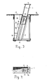
- Fig.3 und 4 eine zweite und die
- Fig.5 und 6 eine dritte Ausführungsform der Panzersperre in analoger Darstellung.
- Bei allen dargestellten Ausführungen ist ein Sperrglied 1 in einer Führungshülse 2 verschiebbar angeordnet. Das Sperrglied 1 ist zum einen als I-Träger mit einer Mittelwand 3 (Fig.1-4) und zum anderen als Vierkantrohr (Fig.5,6) ausgebildet. Es trägt im übrigen eine Abdeckplatte 4 und ist in der Führungshülse 2 vollständig versenkbar. In der vollständig versenkten Stellung des Sperrgliedes 1 fluchtet die Abdeckplatte 4 mit der Fahrbahn 5 und deckt die Führungshülse 2 ab. Ein Hub- und Senkantrieb für das Sperrglied 1 ist weiter unten näher erläutert und stationär ebenfalls unter dem Niveau der Fahrbahn 5 angeordnet.
- Das Sperrglied 1 und der weiter unten erläuterte Hub- und Senkantrieb sind innerhalb eines Containers untergebracht, dessen Basiswand und Seitenwände beim Einschütten des Containers in einer Bodenöffnung mit mit der Fahrbahn 5 niveaugleicher Deckwand des Containers als Schalung dienen. Bei den Ausführungen der Fig.1 bis 4 ist die Führungshülse 2 an der Basiswand und an der Deckwand des Containers zur sperrbaren Fahrtrichtung hin geneigt angeschweißt. Bei der Ausführung der Fig.5 und 6 stellt die Führungshülse 2 im wesentlichen selbst den Container dar.
- Gemäß Fig.1 und 2 greift am Sperrglied 1 ein Hub- und Senkantrieb in Form eines Seilantriebes 6 an. Die Führungshülse 2 weist einen Längsschlitz auf, entlang welchem das Seil des Seiltriebes 6 verläuft. Durch den Längsschlitz ragt ein Mitnehmer 7 zwischen dem Seil und dem Sperrglied 1. In Fig.1 sind im weiteren drei Umlenkräder und ein Antriebsmittel 8 des Seiltriebes 6 ersichtlich. Durch Bewegen des Antriebsmittels 8 mittels eines Handwerkzeuges 9, das etwa in Fahrbahnniveau auf ein Anschlu ßstuck des Antriebsmittels 8 gesteckt werden kann, kann der Seiltrieb 6 in der gewünschten Richtung betätigt werden.
- Bei der Ausführungsform der Fig.3 und 4 greifen am Sperrglied 1 beiderseits seiner Mittelwand 3 angeordnete Kolben- Zylindereinrichtungen 11 an; diese sind druckluftbetrieben und kolbenstangenlos ausgebildet. Durch die Wand des Zylinders ragt seitlich ein mit dessen Kolben verbundener Mitnehmer 12, der gegenüber der Wand des Zylinders abgedichtet ist und am Sperrglied 1 kraftübertragend angreift, Die Kolben-Zylindereinrichtungen 11 stützen sich mit ihrem unteren Ende an der Basiswand des Containers ab. An ihrem oberen Ende sind sie an einem Führungsteil 13 befestigt, an welchem das Sperrglied 1 bei der Hub- und Senkbewegung entlanggleiten kann. Die beiden Druckluftzylinder der Zylinder-Kolben-einrichtungen 11 sind unten über eine Druckluftleitung 14 und oben über eine Druckluftleitung 15 mit einer Druckmittelquelle 16 (in Form einer Preßluftflasche) verbunden. Es können entweder die unteren Räume der beiden Zylinder oder deren obere Räume gemeinsam und gleichzeitig mit Druckluft beaufschlagt werden. Die Druckmittelquelle 16 ist innerhalb des Containers nach Öffnen eines Deckwandteiles 17 zugänglich angeordnet. Die Kolben-Zylindereinrichtungen 11 sind an einem (in den Fig.3 und 4 nicht sichtbaren) Längsträger befestigt, der in der Führungshülse 2 ausziehbar angeordnet ist und sich an der Basiswand des Containers abstützt. Nach Lösen von Kupplungen 18 der Druckluftleitungen 14,15 kann der Längsträger mitsamt den Kolben-Zylindereinrichtungen 11 gemeinsam mit dem Sperrglied 1 zur Wartung bzw. Reparatur aus der Führungshülse 2 herausgezogen werden.
- Bei der Panzersperre nach den Fig.5 und 6 greift am Sperrglied 1 (welches als Vierkantrohr ausgebildet ist) eine einzige, in dessen Innerem angeordnete Kolben-Zylindereinrichtung 11' an. Die Kolben-Zylindereinrichtung 11' ist hier mit einer konventionellen Kolbenstange ausgebildet. Die Führungshülse 2 weist einen parallel zum Sperrglied 1 verlaufenden Schacht 20 auf, in dem die Druckluftleitungen 14' und 15' zur Versorgung der Kolben-Zylindereinrichtung 11' geführt sind. In diesem Schacht 20 befindet sich auch eine parallel zum Sperrglied 1 angeordnete Spindel eines Spindelantriebes 21. Ein Mitnehmer 22 des Spindelantriebes 21 greift durch einen Längsschlitz der Führungshülse 2 unten am Sperrglied 1 an. Der Spindelantrieb 21 ist mittels eines bei 23 aufsteckbaren Handwerkzeuges (Kurbel) betätigbar und dient als Notantrieb für den Fall des Ausfalles der Druckluft, welche die Kolben-Zylindereinrichtung 11' beaufschlagt. Ein Gehäuse mit in den Druckluftleitungen 14', 15' angeordneten Steuerventilen ist in Fig.5 mit 24 bezeichnet. Die Druckluftleitungen 14', 15' führen zu einer (nicht dargestellten) Druckluft-Versorgungszentrale.
- Im übrigen sind in Fig.5 eine an der Vorderseite des Sperrgliedes 1 befestigte beschußsichere Panzerschürze 25 und am Sperrglied 1 angeordnete Gleitstücke oder Führungsrollen 26 ersichtlich.
Claims (11)
Applications Claiming Priority (2)
| Application Number | Priority Date | Filing Date | Title |
|---|---|---|---|
| AT3262/84 | 1984-10-12 | ||
| AT326284A AT384670B (de) | 1984-10-12 | 1984-10-12 | Panzersperre |
Publications (2)
| Publication Number | Publication Date |
|---|---|
| EP0177895A2 true EP0177895A2 (de) | 1986-04-16 |
| EP0177895A3 EP0177895A3 (de) | 1987-02-25 |
Family
ID=3547863
Family Applications (1)
| Application Number | Title | Priority Date | Filing Date |
|---|---|---|---|
| EP85112510A Withdrawn EP0177895A3 (de) | 1984-10-12 | 1985-10-03 | Panzersperre |
Country Status (2)
| Country | Link |
|---|---|
| EP (1) | EP0177895A3 (de) |
| AT (1) | AT384670B (de) |
Cited By (14)
| Publication number | Priority date | Publication date | Assignee | Title |
|---|---|---|---|---|
| EP0211688A1 (de) * | 1985-08-19 | 1987-02-25 | William T. Riley | Spontan verfügbare Strassensperre |
| DE8707078U1 (de) * | 1987-05-16 | 1987-10-15 | Manfred Fladung GmbH, 8752 Mömbris | Sperrpfosten |
| GB2210091A (en) * | 1987-09-21 | 1989-06-01 | Eric Claud Bailey | Traffic bollard |
| FR2687702A1 (fr) * | 1992-02-25 | 1993-08-27 | Patrick Vassal | Borne escamotable motorisee. |
| EP0627527A1 (de) * | 1993-06-04 | 1994-12-07 | INNOVATRON INDUSTRIES, Société Anonyme | Anlage zum Tragen von Strassenmobilär, senkbar mit elektronische Antriebsmitteln |
| FR2743097A1 (fr) * | 1995-12-29 | 1997-07-04 | Sarl Ferinox | Systeme de borne retractable |
| RU2132531C1 (ru) * | 1998-06-04 | 1999-06-27 | Закрытое акционерное общество "АРЛИ спецтехника" | Заграждение для наземных транспортных средств и живой силы |
| RU2212622C1 (ru) * | 2002-01-28 | 2003-09-20 | Калининградский военный институт ФПС РФ | Способ устройства противотанкового заграждения |
| RU2348891C1 (ru) * | 2007-07-02 | 2009-03-10 | Николай Борисович Болотин | Устройство для предотвращения террористического акта |
| RU2349866C1 (ru) * | 2007-06-28 | 2009-03-20 | Николай Борисович Болотин | Устройство для предотвращения террористического акта |
| RU2353890C1 (ru) * | 2007-07-04 | 2009-04-27 | Николай Борисович Болотин | Устройство для предотвращения террористического акта |
| RU2353889C1 (ru) * | 2007-07-04 | 2009-04-27 | Николай Борисович Болотин | Система для предотвращения террористического акта |
| PL423250A1 (pl) * | 2017-10-24 | 2019-05-06 | Karol Jakub Ulc | System zapory przeciwko ciężkim pojazdom, zwłaszcza pancernym, sposób utworzenia rowu przeciwko ciężkim pojazdom, zwłaszcza pancernym oraz segment pneumatyczny zwłaszcza do budowy zapory przeciwko ciężkim pojazdom |
| CN116379840A (zh) * | 2023-05-04 | 2023-07-04 | 中国海洋大学 | 一种军事用防两栖作战车登陆装置及防登陆设备 |
Families Citing this family (1)
| Publication number | Priority date | Publication date | Assignee | Title |
|---|---|---|---|---|
| DE19643815C1 (de) * | 1996-10-30 | 1997-11-20 | Butting H Gmbh & Co Kg | Absperrvorrichtung für Verkehrsflächen |
Family Cites Families (9)
| Publication number | Priority date | Publication date | Assignee | Title |
|---|---|---|---|---|
| US1497073A (en) * | 1921-03-16 | 1924-06-10 | Conan A Doyle | Traffic regulator |
| FR819804A (fr) * | 1936-08-17 | 1937-10-27 | Defawes Freres | Dispositif d'arrêtoirs de véhicules |
| FR1023190A (fr) * | 1950-08-10 | 1953-03-16 | A Marrel Ets | Perfectionnements aux bornes escamotables |
| US3086430A (en) * | 1959-01-28 | 1963-04-23 | David T Emmel | Traffic control equipment |
| DE2048780C3 (de) * | 1970-10-05 | 1975-02-13 | Heinrich 4812 Brackwede Kirschbaum | Quer zur Fahrbahn, insbesondere vor Verkehrsampeln angeordnete Absperrvorrichtung |
| DE2158977C3 (de) * | 1971-11-27 | 1974-10-03 | Fischer Stahlbau, 4000 Duesseldorf | Ausfahrbare Sperre zum vorübergehenden Absperren von Straßen, Plätzen od.dgl |
| IT1027354B (it) * | 1974-01-28 | 1978-11-20 | Bonvin Francois | Dispositivo per sbarrare a volon ta l accesso dei veicoli in un area di parcheggio o in una strada |
| GB2079356A (en) * | 1980-07-03 | 1982-01-20 | Wilson Colin Hutchinson | Retractable road surface ramps |
| DE3303451A1 (de) * | 1983-02-02 | 1984-08-02 | Heinz 8060 Dachau Dalen | Versenkbarer absperrpfosten |
-
1984
- 1984-10-12 AT AT326284A patent/AT384670B/de not_active IP Right Cessation
-
1985
- 1985-10-03 EP EP85112510A patent/EP0177895A3/de not_active Withdrawn
Cited By (19)
| Publication number | Priority date | Publication date | Assignee | Title |
|---|---|---|---|---|
| EP0211688A1 (de) * | 1985-08-19 | 1987-02-25 | William T. Riley | Spontan verfügbare Strassensperre |
| DE8707078U1 (de) * | 1987-05-16 | 1987-10-15 | Manfred Fladung GmbH, 8752 Mömbris | Sperrpfosten |
| DE3816644A1 (de) * | 1987-05-16 | 1988-11-24 | Fladung Gmbh Manfred | Sperrpfosten |
| DE3816644C2 (de) * | 1987-05-16 | 2001-10-18 | Fladung Gmbh Manfred | Sperrpfosten |
| GB2210091A (en) * | 1987-09-21 | 1989-06-01 | Eric Claud Bailey | Traffic bollard |
| GB2210091B (en) * | 1987-09-21 | 1992-01-22 | Eric Claud Bailey | Bollard |
| FR2687702A1 (fr) * | 1992-02-25 | 1993-08-27 | Patrick Vassal | Borne escamotable motorisee. |
| US5469936A (en) * | 1993-06-04 | 1995-11-28 | Lauga; Olivier | Support device for an item of retractable street furniture having electrical actuation |
| FR2705979A1 (fr) * | 1993-06-04 | 1994-12-09 | Innovatron Ind Sa | Dispositif support d'élément de mobilier urbain escamotable à actionneur électrique. |
| EP0627527A1 (de) * | 1993-06-04 | 1994-12-07 | INNOVATRON INDUSTRIES, Société Anonyme | Anlage zum Tragen von Strassenmobilär, senkbar mit elektronische Antriebsmitteln |
| FR2743097A1 (fr) * | 1995-12-29 | 1997-07-04 | Sarl Ferinox | Systeme de borne retractable |
| RU2132531C1 (ru) * | 1998-06-04 | 1999-06-27 | Закрытое акционерное общество "АРЛИ спецтехника" | Заграждение для наземных транспортных средств и живой силы |
| RU2212622C1 (ru) * | 2002-01-28 | 2003-09-20 | Калининградский военный институт ФПС РФ | Способ устройства противотанкового заграждения |
| RU2349866C1 (ru) * | 2007-06-28 | 2009-03-20 | Николай Борисович Болотин | Устройство для предотвращения террористического акта |
| RU2348891C1 (ru) * | 2007-07-02 | 2009-03-10 | Николай Борисович Болотин | Устройство для предотвращения террористического акта |
| RU2353890C1 (ru) * | 2007-07-04 | 2009-04-27 | Николай Борисович Болотин | Устройство для предотвращения террористического акта |
| RU2353889C1 (ru) * | 2007-07-04 | 2009-04-27 | Николай Борисович Болотин | Система для предотвращения террористического акта |
| PL423250A1 (pl) * | 2017-10-24 | 2019-05-06 | Karol Jakub Ulc | System zapory przeciwko ciężkim pojazdom, zwłaszcza pancernym, sposób utworzenia rowu przeciwko ciężkim pojazdom, zwłaszcza pancernym oraz segment pneumatyczny zwłaszcza do budowy zapory przeciwko ciężkim pojazdom |
| CN116379840A (zh) * | 2023-05-04 | 2023-07-04 | 中国海洋大学 | 一种军事用防两栖作战车登陆装置及防登陆设备 |
Also Published As
| Publication number | Publication date |
|---|---|
| ATA326284A (de) | 1987-05-15 |
| AT384670B (de) | 1987-12-28 |
| EP0177895A3 (de) | 1987-02-25 |
Similar Documents
| Publication | Publication Date | Title |
|---|---|---|
| EP0177895A2 (de) | Panzersperre | |
| EP3691985A1 (de) | Verfahren zum errichten einer aufzugsanlage mit zunehmender nutzbarer hubhöhe | |
| DE3608788A1 (de) | Vertikal ausfahrbarer und wiedereinfahrbarer poller als strassensperre zum stoppen von fahrzeugen | |
| CH667595A5 (de) | Einsatzfahrzeug. | |
| DE1919726A1 (de) | Hebevorrichtung,insbesondere fuer Mannlochdeckel | |
| DE3743393A1 (de) | Vorrichtung zur energieversorgung von luftfahrzeugen | |
| DE1965142A1 (de) | Einrichtung zum Parken zweier Fahrzeuge uebereinander | |
| EP0690176B1 (de) | Leitschwellenstrang | |
| EP0845557B1 (de) | Motorbetriebenes Bodenverdichtungsgerät | |
| DE3620349A1 (de) | Sperrsaeule zur absperrung von parkier-, spiel- oder sonstigem absperraum | |
| DE10108432A1 (de) | Hochziehbare Kletterwand | |
| DE3145377C2 (de) | Gabelanordnung an einem Lastaufnahmemittel für Förderzeuge | |
| EP3569765B1 (de) | Fahrbahnbegrenzungselement, sowie verfahren zur öffnung eines fahrbahnbegrenzungselements und verwendung einer fluidtechnischen vorrichtung zum öffnen eines fahrbahnbegrenzungselements | |
| EP0283789A1 (de) | Vorrichtung für einen Kran oder dergleichen | |
| DE2852305A1 (de) | Vorrichtung fuer den gesteuerten eingriff der werkzeuge einer gewinnungsmaschine | |
| DE3522840C1 (de) | Vorrichtung zur Längsverlagerung eines Strecken-Kurzförderers relativ zu einem Widerlager | |
| EP0059972B1 (de) | Ausbaumontagebühne für Strecken des Untertagebetriebes | |
| DE4317516A1 (de) | Gleisloses Lorensystem zum Materialtransport in einer Rohrprofilstrecke | |
| DE3232899C2 (de) | ||
| DE3446059A1 (de) | Ladeaufbau fuer ein strassentransportfahrzeug und mit einem derartigen aufbau ausgeruestetes strassentransportfahrzeug | |
| DE3602902C2 (de) | ||
| EP0881343A1 (de) | Parkvorrichtung mit mindestens zwei übereinander angeordneten Kraftfahrzeug-Stellplätzen | |
| DE4101261C2 (de) | Hubbalken für Einschienenhängebahnen | |
| EP0091587B1 (de) | Kokskuchenführungswagen | |
| DE2800129A1 (de) | Hubbalken zum transportieren schwerer lasten, insbesondere fuer den untertaegigen grubenbetrieb |
Legal Events
| Date | Code | Title | Description |
|---|---|---|---|
| PUAI | Public reference made under article 153(3) epc to a published international application that has entered the european phase |
Free format text: ORIGINAL CODE: 0009012 |
|
| AK | Designated contracting states |
Kind code of ref document: A2 Designated state(s): BE CH DE FR GB IT LI LU NL SE |
|
| PUAL | Search report despatched |
Free format text: ORIGINAL CODE: 0009013 |
|
| AK | Designated contracting states |
Kind code of ref document: A3 Designated state(s): BE CH DE FR GB IT LI LU NL SE |
|
| STAA | Information on the status of an ep patent application or granted ep patent |
Free format text: STATUS: THE APPLICATION IS DEEMED TO BE WITHDRAWN |
|
| 18D | Application deemed to be withdrawn |
Effective date: 19870826 |
|
| RIN1 | Information on inventor provided before grant (corrected) |
Inventor name: HANTL, HANNES Inventor name: KOSS, ARTUR |