EP0178018B1 - Nivellierungsmechanismus für die Reinigungseinrichtung eines Mähdreschers - Google Patents
Nivellierungsmechanismus für die Reinigungseinrichtung eines Mähdreschers Download PDFInfo
- Publication number
- EP0178018B1 EP0178018B1 EP19850201582 EP85201582A EP0178018B1 EP 0178018 B1 EP0178018 B1 EP 0178018B1 EP 19850201582 EP19850201582 EP 19850201582 EP 85201582 A EP85201582 A EP 85201582A EP 0178018 B1 EP0178018 B1 EP 0178018B1
- Authority
- EP
- European Patent Office
- Prior art keywords
- shaker shoe
- main frame
- fore
- aft
- shoe means
- Prior art date
- Legal status (The legal status is an assumption and is not a legal conclusion. Google has not performed a legal analysis and makes no representation as to the accuracy of the status listed.)
- Expired
Links
- 238000004140 cleaning Methods 0.000 title claims description 51
- 230000007246 mechanism Effects 0.000 title claims description 39
- 230000000694 effects Effects 0.000 claims description 11
- 239000012530 fluid Substances 0.000 claims description 9
- 238000004891 communication Methods 0.000 claims description 3
- 238000012546 transfer Methods 0.000 claims description 2
- 230000004044 response Effects 0.000 claims 2
- 230000024042 response to gravity Effects 0.000 claims 1
- 241001124569 Lycaenidae Species 0.000 description 6
- 239000000463 material Substances 0.000 description 6
- 230000005484 gravity Effects 0.000 description 5
- 238000004519 manufacturing process Methods 0.000 description 3
- 238000010276 construction Methods 0.000 description 2
- 230000008030 elimination Effects 0.000 description 2
- 238000003379 elimination reaction Methods 0.000 description 2
- 238000003306 harvesting Methods 0.000 description 2
- 238000012423 maintenance Methods 0.000 description 2
- 239000010813 municipal solid waste Substances 0.000 description 2
- 238000013459 approach Methods 0.000 description 1
- 238000013461 design Methods 0.000 description 1
- 238000011161 development Methods 0.000 description 1
- 238000010586 diagram Methods 0.000 description 1
- 230000003292 diminished effect Effects 0.000 description 1
- 238000007599 discharging Methods 0.000 description 1
- 230000007935 neutral effect Effects 0.000 description 1
- 230000001376 precipitating effect Effects 0.000 description 1
- 238000007789 sealing Methods 0.000 description 1
- 238000003860 storage Methods 0.000 description 1
- 230000000153 supplemental effect Effects 0.000 description 1
Images



Classifications
-
- A—HUMAN NECESSITIES
- A01—AGRICULTURE; FORESTRY; ANIMAL HUSBANDRY; HUNTING; TRAPPING; FISHING
- A01D—HARVESTING; MOWING
- A01D75/00—Accessories for harvesters or mowers
- A01D75/28—Control mechanisms for harvesters or mowers when moving on slopes; Devices preventing lateral pull
- A01D75/285—Control mechanisms for harvesters or mowers when moving on slopes; Devices preventing lateral pull with arrangements for holding the harvesting or mowing apparatus in a horizontal position
-
- A—HUMAN NECESSITIES
- A01—AGRICULTURE; FORESTRY; ANIMAL HUSBANDRY; HUNTING; TRAPPING; FISHING
- A01D—HARVESTING; MOWING
- A01D75/00—Accessories for harvesters or mowers
- A01D75/28—Control mechanisms for harvesters or mowers when moving on slopes; Devices preventing lateral pull
- A01D75/282—Control mechanisms for harvesters or mowers when moving on slopes; Devices preventing lateral pull acting on the grain cleaning and separating device
Definitions
- the present invention relates generally to combine harvesters and, more particularly, to improvements in the cleaning apparatus of such harvesters to permit a fore-and-aft leveling thereof when the combine is operating under fore-and-aft inclined operating conditions.
- the present invention also relates to improvements in the cleaning apparatus of combine harvesters which permit a leveling thereof when the combine is operating under both transverse and fore-and-aft inclined operating conditions.
- US-A 3 731 470 Attempts to maintain a combine cleaning apparatus in a horizontal orientation while the combine is operating under sidehill conditions can be found in US-A 3 731 470 and in US-A 4 344 443.
- the apparatus disclosed in the US-A 3 731 470 provides a leveling of the entire frame of the combine through the operation of hydraulic cylinders to maintain the cleaning apparatus in a generally horizontal orientation. Since the entire combine is maintained in a level orientation, it was necessary to modify the connection of the crop harvesting header to the combine to permit a proper gathering of the crop material to be harvested.
- the apparatus disclosed in the US-A 4 344 443 provides for a leveling of the entire cleaning mechanism, including the fan, about a longitudinally extending pivot axis; however, this mechanism does not provide for fore-and-aft leveling of the cleaning apparatus.
- the utilization of this leveling mechanism requires the use of a more complex, and therefore more expensive, main frame and drive train components. This complexity makes the elimination of a leveling mechanism to provide a "stationary" cleaning apparatus for use on flat land operations impractical.
- the mechanism according to US-A 4 344 443 is expensive to manufacture, is cumbersome to operate, results in an unnecessary shifting of major structural components and does not produce an overall leveling of the grain pan and chaffer sieve.
- US-A 2 831 577 An attempt to maintain a combine cleaning apparatus in a longitudinal, generally horizontal orientation while the combine harvester is operating under fore-and-aft inclined operating conditions, has been disclosed in US-A 2 831 577.
- a shaker shoe supporting the cleaning sieves is mounted for pivotal movement around the transverse axis of a fan structure of which the housing also is pivotally movable in unison with the shaker shoe around said axis.
- the grain pan structure according to US-A 2 831 577 comprises driven conveyor means operable to convey threshed grain to the cleaning sieves and pivotally coupled to the shaker shoe to maintain the delivery end above the receiving end of the cleaning sieves. This results in a fairly complicated mounting and drive arrangement of the grain pan structure.
- a four-way leveling mechanism for a combine cleaning apparatus is shown in US-A 2 587 918.
- a ball mounting enables the cleaning unit including sieves, a fan and a vibrating mechanism, to tilt in any direction to maintain said unit in a level condition.
- a weight or pendulum is provided to accomplish this four-way leveling.
- this approach of four-way leveling of a cleaning apparatus for combine harvesters is no longer practical for use on modern combine harvesters having much larger cleaning means.
- Another four-way leveling combine cleaning apparatus is principally disclosed in DE-A 3 200 327.
- the combine harvester has a mobile main frame and a cleaning mechanism supported thereby in flow communication with a threshing and separating mechanism to receive threshed grain therefrom and to clean debris from said threshed grain.
- Said cleaning mechanism comprises:
- the grain pan means and the sieve means are mounted on the shaker shoe means via the intermediary of a subframe; said subframe being supported on said shaker shoe means for pivotal movement around a generally longitudinal axis relative to said shaker shoe means.
- Further position control means are operatively associated with said subframe to pivotally move said subframe with the grain pan means and sieve means thereon about said generally longitudinal axis to permit maintaining a generally level attitude thereof in the transverse direction irrespective of the transverse attitude of the main frame.
- the instant invention provides a mechanism for leveling only the grain pan and the chaffer sieve, whereby the weight of the structural elements pivotally supported for movement is minimized permitting an improved leveling operation.
- the fan and supporting structural components are not pivotally supported for leveling movement.
- a lower sieve can be suspended from the main frame below the chaffer sieve without the leveling movement of the chaffer sieve affecting the movement of the lower sieve.
- the invention also provides a leveling mechanism for a combine cleaning apparatus without requiring complex main frame structure and drive components. It is also a feature of the invention that the leveling cleaning mechanism easily and quickly can be replaced by a conventional cleaning mechanism to provide an inexpensive flat lands combine with a "stationary" cleaning mechanism. Alternatively, the combine harvester according to the instant invention also easily and quickly can be transformed into a flat lands combine with a "stationary" cleaning mechanism by the mere elimination of the actuators and the control apparatus.
- the instant invention provides a leveling mechanism for the cleaning apparatus of a combine harvester which is durable in construction, inexpensive of manufacture, carefree of maintenance, facile in assemblage, and simple and effective in use.
- FIG. 1 a side elevational view of a combine harvester incorporating the principles of the instant invention, can be seen. Any left and right references are used as a matter of convenience and are determined with reference to the direction of forward operative travel.
- the combine 10 is provided with a main frame 12 having at least one transversely disposed beam 13 mobilely supported over the ground G by wheels 14.
- a crop harvesting header 15 is forwardly supported from the frame 12 to gather crop material and convey it rearwardly via a feeding mechanism 17 to a threshing and separating mechanism 19.
- the threshing and separating mechanism 19 is operable to thresh the crop material fed thereto and separate the threshed grain from the trash material by precipitating the threshed grain downwardly through the threshing and separating mechanism 19 while discharging the trash material along a separate path to be deposited on the ground G rearward of the combine 10.
- a cleaning mechanism 20 is positioned beneath the threshing and separating mechanism 19 to receive the threshed grain precipitated therefrom on a grain pan 22.
- the cleaning mechanism 20 is operatively connected to an eccentric drive 24 to effect a generally fore-and-aft reciprocating movement of the cleaning mechanism 20 to convey the threshed grain in a rearward direction.
- Sieve means 25 are positioned rearwardly of the grain pan 22 to receive threshed grain conveyed rearwardly therefrom and clean the threshed grain from chaff and other debris conveyed therewith.
- the sieve means 25 include an upper chaffer sieve 26 and a lower cleaning sieve 28 mounted for opposing fore-and-aft reciprocating movement and in flow communication with air being blown from a fan 29 upwardly therethrough to remove chaff and debris from the threshed grain. It can be seen that, when in a normal horizontal orientation, the sieves 26, 28 have a slightly upward inclination in a rearward direction. Cleaned grain passing through the sieve means 25 is conveyed into a storage tank 18 supported on the main frame 12.
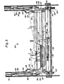
- the grain pan 22 and chaffer sieve 26 are mounted in a subframe 31 which in turn is pivotally supported by fore-and-aft extending and longitudinally spaced pivots 33, 34 within a shaker shoe 35.
- a tailings return section 27 is positioned at the rear of the chaffer sieve 26 and is pivotally movable therewith.
- the tailings return section 27 is cooperable with conventional apparatus for returning unthreshed heads to the threshing and separating means 19.
- the shaker shoe 35 is movably supported from the frame 12 by front connecting links 36, rearward connecting links 37, and central connecting links 38.
- Each of the connecting links 36, 37, 38 incorporate rubber bushings in a conventional manner to permit a generally fore-and-aft reciprocating movement induced by drive arms 41 interconnecting the eccentric drive 24 and the rearward links 37 supporting the shaker shoe 35.
- the lower cleaning sieve 28 is supported from the frame 12 by the central connecting links 38 and supplemental connecting links 39 in a similar manner to permit a generally fore-and-aft reciprocating movement.
- the shaker shoe 35 is provided with inwardly directed arcuate side members 42 to permit a sealing cooperation with longitudinally extending seals 43 connected to the subframe 31 and sweepingly engaging the inside of said arcuate side members 42 during pivotal movement of the subframe 31 relative to the shaker shoe 35.
- Additional longitudinally extending seals 44 are connected to the side members 42 of the shaker shoe 35 to sealingly engage vertically extending sidewalls 46 of the combine 10 to prevent the loss of threshed grain between the shaker shoe 35 and the sidewalls 46.
- the subframe 31 is provided with a downwardly extending actuating arm 48.
- a hydraulic cylinder 50 interconnects a mounting tab 52 connected to the shaker shoe 35 and the actuating arm 48 for the pivotal movement of the subframe 35 about a fore-and-aft extending axis 53 defined by the front and back pivots 33, 34.
- An adjustable stop bolt 49 engageable with the shaker shoe 35 serves as a limit to the amount of pivotal movement permitted to the subframe 31 in one direction, while that the end of the retraction stroke of the cylinder 50 limits the movement of the subframe 31 in the opposing direction.
- the hydraulic cylinder 50 is operatively associated with a hydraulic system 70, described in greater detail with reference to Fig. 4 below, to provide a flow of hydraulic fluid under pressure for operation of the cylinder 50.
- the shaker shoe 35 is also mounted for pivotal movement about a transversely extending axis 57 corresponding to the frame mounting points of the front connecting links 36.
- the frame mounting points 59 for the rearward connecting links 37 are movably supported from a pair of transversely spaced hydraulic cylinders 60 to effect a fore-and-aft leveling movement of the shaker shoe 35, and consequently also of the grain pan 22 and chaffer sieve 26, through a pivotal movement of the shaker shoe 35 about the forwardly disposed transverse pivot axis 57 by raising and lowering the rearward end of the shaker shoe 35.
- the center connecting links 38 include telescoping portions 62, permitting a relative vertical movement between the chaffer sieve 26 and the lower cleaning sieve 28.
- the frame mounting points 59 are housed in plates 64 positioned within generally vertically extending guides 65 to guide the movement of the plates 64.
- the hydraulic cylinders 50, 60 are operably associated with the hydraulic system 70.
- a first solenoid valve 72 controls the direction of hydraulic fluid flow to the hydraulic cylinder 50, while that a second solenoid valve 74 controls the flow of hydraulic fluid to the hydraulic cylinders 60.
- the solenoid valves 72, 74 can be positioned to direct fluid to the respective hydraulic cylinders for either extension or retraction thereof or to circulate fluid back to the reservoir 76 without effecting any movement of the hydraulic cylinders 50, 60.
- the positioning of the solenoid valves 72, 74 is controlled through an electrical circuit 78 connected to a battery 79 serving as a source of electrical power and to a pair of inclinometers 80, 90.
- Each inclinometer 80, 90 includes a master member 82, 92 having a first electrical contact 83, 93 and a spaced apart second electrical contact 84, 94.
- a pendulum 85, 95 is pivotally mounted within the respective master member 82, 92 for movement with the force of gravity relative to the master member 82, 92.
- the pendulum 85, 95 carries a third electrical contact 86, 96 engageable with the respective first and second contacts to close the electrical circuit 78 and send a flow of electrical current from the battery 79 to the respective solenoid valve 72, 74 as described in greater detail below.
- the position of the master members 82, 92 relative to the main frame 12 is controlled through control links 89, 99 in a manner also further described below.
- the lateral inclinometer 80 is mounted on a transversely extending beam 13 forming a part of the main frame 12. As the combine 10 encounters side hill operating conditions, the transverse beam 13 becomes inclined to the horizontal. However, the pendulum 85 follows the force of gravity and moves relative to the master member 82. Sufficient lateral inclination of the combine 10 will cause the third contact 86 to engage either the first or second contact 83, 84 to close the electrical circuit and to direct a flow of hydraulic fluid to the hydraulic cylinder 50, which in turn effects a pivotal movement of the subframe 31 relative to the shaker shoe 35 to move the subframe 31 toward a level orientation relative to the shaker shoe 45 and the main frame 12.
- the operation of the hydraulic system 70 to control the fore-and-aft leveling operation is similar to the lateral leveling operation described above.
- the longitudinal inclinometer 90 is mounted on a fore-and-aft extending frame member 16 to sense the inclination thereof in a manner similar to that described above for the lateral inclinometer. Movement of the pedulum 95 relative to the master member 92 is induced by the force of gravity and effects an engagement of the third contact member 96 with one of the first or second contacts 93, 94. The result is a closing of the electrical circuit 78 to energize the solenoid valve 74 and direct the flow of hydraulic fluid to the hydraulic cylinders 60 to cause a pivotal movement of the shaker shoe 35 about the transverse pivot axis 57.
- the movement of the plates 64 housing the rearward frame pivots 59 causes the control linkage 99 coupled to one of said plates 64 to move the master member 92 relative to the longitudinal frame member 16 and the pendulum 95 until the electrical circuit 78 is broken and the shaker shoe 35 has attained a generally horizontal fore-and-aft orientation.
- One skilled in the art will readily realize that operation of the fore-and-aft and lateral leveling mechanisms described above will result in a maintenance of the grain pan 22 and chaffer sieve 26 in a generally horizontal orientation in both the fore-and-aft and transverse directions irrespective of the actual orientation of the main frame 12 when the combine 10 is operating uphill, downhill or on sidehills in either direction.
Landscapes
- Life Sciences & Earth Sciences (AREA)
- Environmental Sciences (AREA)
- Threshing Machine Elements (AREA)
Claims (17)
Applications Claiming Priority (4)
| Application Number | Priority Date | Filing Date | Title |
|---|---|---|---|
| US659933 | 1984-10-11 | ||
| US06/659,933 US4548214A (en) | 1984-10-11 | 1984-10-11 | Fore-and-aft leveling mechanism for combine cleaning apparatus |
| US06/659,934 US4557276A (en) | 1984-10-11 | 1984-10-11 | Four way leveling mechanism for combine cleaning apparatus |
| US659934 | 1984-10-11 |
Publications (2)
| Publication Number | Publication Date |
|---|---|
| EP0178018A1 EP0178018A1 (de) | 1986-04-16 |
| EP0178018B1 true EP0178018B1 (de) | 1989-09-06 |
Family
ID=27097933
Family Applications (1)
| Application Number | Title | Priority Date | Filing Date |
|---|---|---|---|
| EP19850201582 Expired EP0178018B1 (de) | 1984-10-11 | 1985-10-01 | Nivellierungsmechanismus für die Reinigungseinrichtung eines Mähdreschers |
Country Status (2)
| Country | Link |
|---|---|
| EP (1) | EP0178018B1 (de) |
| DE (1) | DE3572759D1 (de) |
Families Citing this family (10)
| Publication number | Priority date | Publication date | Assignee | Title |
|---|---|---|---|---|
| EP0547036B1 (de) * | 1987-10-22 | 1997-09-17 | New Holland Belgium N.V. | Reinigungsvorrichtung für Mähdrescher einschliesslich des Zufuhrbodens und der Siebe |
| DE3822689A1 (de) * | 1988-07-05 | 1990-01-11 | Deere & Co | Foerdervorrichtung |
| DE3930949A1 (de) * | 1989-09-15 | 1991-03-28 | Kloeckner Humboldt Deutz Ag | Reinigungsvorrichtung |
| US5527219A (en) * | 1993-07-29 | 1996-06-18 | Schumacher; Gustav | Cleaning sieve for the harvested crop of agricultural machines |
| AT401596B (de) * | 1994-05-27 | 1996-10-25 | Wintersteiger Gmbh & Co | Siebvorrichtung für einen mähdrescher, insbesondere für einen versuchsfeldmähdrescher |
| BR102014027798B1 (pt) * | 2014-11-07 | 2020-10-20 | Bernardo Delfino Bergoli | sistema de nivelamento de sementes em peneiras de colheitadeiras |
| BE1023017B1 (nl) * | 2015-06-30 | 2016-11-04 | Cnh Industrial Belgium Nv | Maaidorser met stroschudders met verstelbare helling |
| CN116982484A (zh) * | 2023-07-17 | 2023-11-03 | 吉林大学 | 一种悬挂式玉米籽粒收获机清选筛调平装置 |
| CN117898128B (zh) * | 2024-03-04 | 2026-03-03 | 江苏大学 | 一种自适应调节清选装置及其控制方法和联合收获机 |
| CN119498101A (zh) * | 2024-12-26 | 2025-02-25 | 西北农林科技大学 | 一种背负式小麦收获机割台装置的横向调平机构 |
Family Cites Families (6)
| Publication number | Priority date | Publication date | Assignee | Title |
|---|---|---|---|---|
| US2801511A (en) * | 1954-05-17 | 1957-08-06 | Deere & Co | Leveling control system for agricultural machine |
| US2796717A (en) * | 1954-11-01 | 1957-06-25 | Internaltional Harvester Compa | Hillside harvester thresher |
| US2871646A (en) * | 1957-07-30 | 1959-02-03 | Deere & Co | Hillside combine |
| US2831577A (en) * | 1957-08-12 | 1958-04-22 | Farber Frank | Levelling the grain cleaning and separating mechanism in harvesters |
| DE3024902A1 (de) * | 1979-07-04 | 1981-01-22 | Sperry Nv | Koerner-reinigungsvorrichtung fuer maehdrescher |
| DE3200327A1 (de) * | 1982-01-08 | 1983-07-21 | Günther 3210 Elze Heuer | "maehdrescher" |
-
1985
- 1985-10-01 EP EP19850201582 patent/EP0178018B1/de not_active Expired
- 1985-10-01 DE DE8585201582T patent/DE3572759D1/de not_active Expired
Also Published As
| Publication number | Publication date |
|---|---|
| DE3572759D1 (en) | 1989-10-12 |
| EP0178018A1 (de) | 1986-04-16 |
Similar Documents
| Publication | Publication Date | Title |
|---|---|---|
| US4557276A (en) | Four way leveling mechanism for combine cleaning apparatus | |
| US4548214A (en) | Fore-and-aft leveling mechanism for combine cleaning apparatus | |
| EP0178017B1 (de) | Seitlicher Nivellierungsmechanismus für die Reinigungseinrichtung eines Mähdreschers | |
| US4344443A (en) | Cleaning apparatus of combine harvesters | |
| US4897071A (en) | Combine harvester cleaning apparatus | |
| US4724661A (en) | Two piece crop harvesting header and flotation mechanism therefor | |
| CA1108870A (en) | Articulated combine | |
| EP3117697B1 (de) | Erntevorsatzneigungsmechanismus | |
| US7726111B2 (en) | Suspension system for a belt pickup header in an agricultural harvester | |
| US6510680B2 (en) | Apparatus and method for pivotal adjustment of a frontal attachment in an agricultural machine | |
| EP1609352B1 (de) | Getreidereinigung im Mähdrescher | |
| US10568267B2 (en) | Harvester separation frame orientation adjustment | |
| EP0198544A1 (de) | Höhenlage- und Schräglageregelung des Schneidwerktisches einer Erntemaschine | |
| GB2042315A (en) | Combine harvester | |
| EP0178018B1 (de) | Nivellierungsmechanismus für die Reinigungseinrichtung eines Mähdreschers | |
| EP2606712B1 (de) | Schneckenbett für ein Reinigungssystem mit seitlicher Nivellierung | |
| US20100064652A1 (en) | Airflow controlled combine shoe | |
| EP3811763B1 (de) | Stützgestänge eines mähbalkens | |
| EP3120687B1 (de) | Seitenrüttlerverbindung für landwirtschaftliches erntemaschinensieb | |
| US2831577A (en) | Levelling the grain cleaning and separating mechanism in harvesters | |
| EP3571921A1 (de) | Reinigungssystem für mähdrescher | |
| JPH0220927Y2 (de) | ||
| JP2000175539A (ja) | コンバイン | |
| JP2548841B2 (ja) | コンバインの刈取前処理装置 | |
| JP2798241B2 (ja) | コンバインにおけるキャビン装置 |
Legal Events
| Date | Code | Title | Description |
|---|---|---|---|
| PUAI | Public reference made under article 153(3) epc to a published international application that has entered the european phase |
Free format text: ORIGINAL CODE: 0009012 |
|
| 17P | Request for examination filed |
Effective date: 19851001 |
|
| AK | Designated contracting states |
Kind code of ref document: A1 Designated state(s): DE FR GB |
|
| RAP1 | Party data changed (applicant data changed or rights of an application transferred) |
Owner name: NEW HOLLAND INC. |
|
| 17Q | First examination report despatched |
Effective date: 19871201 |
|
| RAP1 | Party data changed (applicant data changed or rights of an application transferred) |
Owner name: FORD NEW HOLLAND, INC. (A DELAWARE CORP.) |
|
| GRAA | (expected) grant |
Free format text: ORIGINAL CODE: 0009210 |
|
| AK | Designated contracting states |
Kind code of ref document: B1 Designated state(s): DE FR GB |
|
| REF | Corresponds to: |
Ref document number: 3572759 Country of ref document: DE Date of ref document: 19891012 |
|
| ET | Fr: translation filed | ||
| PLBE | No opposition filed within time limit |
Free format text: ORIGINAL CODE: 0009261 |
|
| STAA | Information on the status of an ep patent application or granted ep patent |
Free format text: STATUS: NO OPPOSITION FILED WITHIN TIME LIMIT |
|
| 26N | No opposition filed | ||
| PGFP | Annual fee paid to national office [announced via postgrant information from national office to epo] |
Ref country code: GB Payment date: 20010921 Year of fee payment: 17 |
|
| PGFP | Annual fee paid to national office [announced via postgrant information from national office to epo] |
Ref country code: FR Payment date: 20011010 Year of fee payment: 17 |
|
| PGFP | Annual fee paid to national office [announced via postgrant information from national office to epo] |
Ref country code: DE Payment date: 20011012 Year of fee payment: 17 |
|
| REG | Reference to a national code |
Ref country code: GB Ref legal event code: IF02 |
|
| PG25 | Lapsed in a contracting state [announced via postgrant information from national office to epo] |
Ref country code: GB Free format text: LAPSE BECAUSE OF NON-PAYMENT OF DUE FEES Effective date: 20021001 |
|
| PG25 | Lapsed in a contracting state [announced via postgrant information from national office to epo] |
Ref country code: DE Free format text: LAPSE BECAUSE OF NON-PAYMENT OF DUE FEES Effective date: 20030501 |
|
| GBPC | Gb: european patent ceased through non-payment of renewal fee |
Effective date: 20021001 |
|
| PG25 | Lapsed in a contracting state [announced via postgrant information from national office to epo] |
Ref country code: FR Free format text: LAPSE BECAUSE OF NON-PAYMENT OF DUE FEES Effective date: 20030630 |
|
| REG | Reference to a national code |
Ref country code: FR Ref legal event code: ST |