EP0178055A2 - Lubrificateur pour une chaîne d'entraînement - Google Patents
Lubrificateur pour une chaîne d'entraînement Download PDFInfo
- Publication number
- EP0178055A2 EP0178055A2 EP85305880A EP85305880A EP0178055A2 EP 0178055 A2 EP0178055 A2 EP 0178055A2 EP 85305880 A EP85305880 A EP 85305880A EP 85305880 A EP85305880 A EP 85305880A EP 0178055 A2 EP0178055 A2 EP 0178055A2
- Authority
- EP
- European Patent Office
- Prior art keywords
- chain
- fluid
- metering pump
- lubricating
- platform arm
- Prior art date
- Legal status (The legal status is an assumption and is not a legal conclusion. Google has not performed a legal analysis and makes no representation as to the accuracy of the status listed.)
- Withdrawn
Links
- 230000001050 lubricating effect Effects 0.000 title claims abstract description 63
- 239000012530 fluid Substances 0.000 claims abstract description 95
- 238000005461 lubrication Methods 0.000 claims abstract description 24
- 238000005086 pumping Methods 0.000 claims description 29
- 230000004044 response Effects 0.000 claims description 3
- 230000037452 priming Effects 0.000 claims 1
- 230000001360 synchronised effect Effects 0.000 claims 1
- 230000009471 action Effects 0.000 description 7
- 239000000314 lubricant Substances 0.000 description 7
- 230000007246 mechanism Effects 0.000 description 7
- 238000012423 maintenance Methods 0.000 description 6
- 238000010586 diagram Methods 0.000 description 3
- 230000000737 periodic effect Effects 0.000 description 3
- 230000009849 deactivation Effects 0.000 description 2
- 238000004891 communication Methods 0.000 description 1
- 238000010276 construction Methods 0.000 description 1
- 230000007423 decrease Effects 0.000 description 1
- 238000005553 drilling Methods 0.000 description 1
- 239000000428 dust Substances 0.000 description 1
- 230000000694 effects Effects 0.000 description 1
- 230000004048 modification Effects 0.000 description 1
- 238000012986 modification Methods 0.000 description 1
Images




Classifications
-
- F—MECHANICAL ENGINEERING; LIGHTING; HEATING; WEAPONS; BLASTING
- F16—ENGINEERING ELEMENTS AND UNITS; GENERAL MEASURES FOR PRODUCING AND MAINTAINING EFFECTIVE FUNCTIONING OF MACHINES OR INSTALLATIONS; THERMAL INSULATION IN GENERAL
- F16N—LUBRICATING
- F16N7/00—Arrangements for supplying oil or unspecified lubricant from a stationary reservoir or the equivalent in or on the machine or member to be lubricated
- F16N7/38—Arrangements for supplying oil or unspecified lubricant from a stationary reservoir or the equivalent in or on the machine or member to be lubricated with a separate pump; Central lubrication systems
-
- B—PERFORMING OPERATIONS; TRANSPORTING
- B65—CONVEYING; PACKING; STORING; HANDLING THIN OR FILAMENTARY MATERIAL
- B65G—TRANSPORT OR STORAGE DEVICES, e.g. CONVEYORS FOR LOADING OR TIPPING, SHOP CONVEYOR SYSTEMS OR PNEUMATIC TUBE CONVEYORS
- B65G45/00—Lubricating, cleaning, or clearing devices
- B65G45/02—Lubricating devices
- B65G45/08—Lubricating devices for chains
-
- F—MECHANICAL ENGINEERING; LIGHTING; HEATING; WEAPONS; BLASTING
- F16—ENGINEERING ELEMENTS AND UNITS; GENERAL MEASURES FOR PRODUCING AND MAINTAINING EFFECTIVE FUNCTIONING OF MACHINES OR INSTALLATIONS; THERMAL INSULATION IN GENERAL
- F16H—GEARING
- F16H57/00—General details of gearing
- F16H57/04—Features relating to lubrication or cooling or heating
- F16H57/05—Features relating to lubrication or cooling or heating of chains
-
- B—PERFORMING OPERATIONS; TRANSPORTING
- B65—CONVEYING; PACKING; STORING; HANDLING THIN OR FILAMENTARY MATERIAL
- B65G—TRANSPORT OR STORAGE DEVICES, e.g. CONVEYORS FOR LOADING OR TIPPING, SHOP CONVEYOR SYSTEMS OR PNEUMATIC TUBE CONVEYORS
- B65G2203/00—Indexing code relating to control or detection of the articles or the load carriers during conveying
- B65G2203/04—Detection means
- B65G2203/042—Sensors
- B65G2203/043—Magnetic
-
- B—PERFORMING OPERATIONS; TRANSPORTING
- B65—CONVEYING; PACKING; STORING; HANDLING THIN OR FILAMENTARY MATERIAL
- B65G—TRANSPORT OR STORAGE DEVICES, e.g. CONVEYORS FOR LOADING OR TIPPING, SHOP CONVEYOR SYSTEMS OR PNEUMATIC TUBE CONVEYORS
- B65G2203/00—Indexing code relating to control or detection of the articles or the load carriers during conveying
- B65G2203/04—Detection means
- B65G2203/042—Sensors
- B65G2203/044—Optical
-
- F—MECHANICAL ENGINEERING; LIGHTING; HEATING; WEAPONS; BLASTING
- F16—ENGINEERING ELEMENTS AND UNITS; GENERAL MEASURES FOR PRODUCING AND MAINTAINING EFFECTIVE FUNCTIONING OF MACHINES OR INSTALLATIONS; THERMAL INSULATION IN GENERAL
- F16N—LUBRICATING
- F16N2210/00—Applications
- F16N2210/33—Chains
Definitions
- This invention relates to automatic lubricator devices and in particular to such automatic lubricator devices for chain conveyor systems.
- Automatic chain lubricating devices are used extensively in industry for automatically applying lubricant under pressure to particular points of chain systems.
- the various types of commercially available chain lubricating devices can be classified as either a moving lubricator nozzle device or fixed lubricator nozzle device.
- Fixed lubricator nozzle devices include fixed lubricator nozzles rigidly mounted to the conveyor track with the lubricant being timed for application to the desired conveyor point by means of a control system actuated by a sensor which detects passage of a particular portion of the conveyor.
- moving lubricator nozzle devices the moving nozzle is controlled in a path to advantageously place the nozzle and the lubricant shot near the conveyor point desired to be lubricated while avoiding conveyor attachments which could damage the nozzles.
- Such moving nozzle devices utilize a mechanical interface to synchronize movement of the nozzle to the conveyor. While such moving lubricator nozzle systems are more accurate than fixed lubricator nozzle systems, they generally require more maintenance due to the increased number of components and to the complexity of the required mechanical interface equipment.
- Moving nozzle lubricators are known.
- One such mechanism manufactured by Applicant moves the lubricating nozzles in a cycloidal path, the points of which pass above a conveyor chain.
- the lubricating nozzles are attached to a caterpillar chain mechanism which properly synchronizes the cycloidal period to the speed of the conveyor chain.
- the caterpillar ch ⁇ ain mechanism is automatically engaged with the conveyor chain by a pneumatically actuated cylinder when a lubrication cycle is necessary.
- a plate mounting the nozzles physically actuates a fluid trip valve when the nozzle is moved into position and enables the lubricating fluid to be delivered to the nozzle.
- This moving nozzle lubricator device functions satisfactorily, but is complex and has many components which require maintenance.
- a second commercially available moving nozzle lubricator is similar to the aforementioned device in that it also employs a caterpillar chain synchronizing mechanism and physical actuation of a fluid trip valve, but with the cycloidal action modified to effect a longer "dwell time" - i.e., the time during which the moving nozzle is in position adjacent the desired conveyor point to be lubricated.
- the modification makes this second commercial unit even more mechanically complex than the first mentioned commercial unit and therefore increases rather than reduces the number of components requiring maintenance.
- nozzles are formed by drilling apertures into sprocket teeth which engage the chain during chain',movement.
- a fluid trip valve is physically actuated when the sprocket teeth are moved during positioning.
- the nozzles formed by the apertures are close to the chain, the axial direction of the nozzles are not toward the desired target area to be .lubricated on the chain. Also, since most conveyor chains are in an industrial environment subject to dust and dirt, the nozzles can become quickly blocked, requiring periodic maintenance.
- a lubricating device and in particular a moving nozzle lubricating device which obviates the need for caterpillar chains and sprockets and thereby reduces maintenance problems.
- an automatic lubricating device for chain conveyors which includes a pivoting arm having a roller at one end for contacting the chain centre links and which can move between the chain side links to place one or more lubricating nozzles substantially along the centre line or longitudinal axis of the chain to deliver lubricating fluid to the desired points on the chain.
- a position sensing mechanism mounted on the pivoting arm determines when the nozzles are in position and activates the lubricating fluid pumping system to deliver a specified quantity of fluid to the chain.
- the pivoting arm provides synchronization of movement of the conveyor chain to the lubricator nozzles and is spring biased inwardly with the roller directed towards the chain.
- a platform portion of the pivoting arm includes means for mounting the roller and lubricating nozzles at one end and means for pivotally mounting the other end of the platform portion with respect to the conveyor chain.
- a magnetic proximity switch mounted on a fixed plate cooperates with an indicator post on the pivoting platform to activate the lubricating pump when the roller has moved into the side link chain portion so that the proximity switch senses the indicator post.
- a moving nozzle type lubricator for conveyor chains is provided with relatively few parts and of easily manufactured components.
- the maintenance of this unique lubricating mechanism is significantly reduced compared to prior art mechanisms.
- an improved lubricating fluid metering pumping apparatus wherein a metering pump includes a pumping chamber with an outlet connected to the lubricating nozzle, and an actuable fluid valve controlling the flow of fluid from a reservoir/pump to the metering pump. Means are provided to enable fluid passage from the pumping chamber to the nozzles, and to selectively prevent such fluid passage immediately at the end of the lubrication cycle so that a clean shot of lubricating fluid is delivered during the lubrication cycle and dripping from the nozzles is substantially eliminated.
- a piston cylinder is provided in the metering pump to divert fluid from the pumping chamber at the end of the lubrication cycles.
- automatic lubricating device 10 includes a platform arm 24 pivotally mounted on a rod 26 which in turn is rigidly mounted by a support arm 28 to the I-beam 18.
- Rod 26 may be threaded at its ends for threadable engagement with nuts 27 (Figure 5) at the top and a nut 27 and bearing block 29 at the bottom to support platform arm 24 at platform arm end 30 adjacent chain 12.
- Bias means such as a spring 32 are provided with one spring end fixed in position and the other spring end mounted to platform arm 24 such that spring 32 urges the opposite platform arm end 34 towards chain 12 so as to be immediately adjacent and in contact with chain centre link 20.
- the platform arm 24 is formed with a first plate 36 joined at one end to a second plate 38 as shown most clearly in Figure 2. While plates 36 and 38 may be welded together, it is preferred that instead they be mounted together with nuts and bolts with one of the plates having a slot so that the plates can be adjustably positioned before being securely attached to each other. Thus, adjustable mounting of plate 38 on plate 36 permits adjustable mounting of plate end 34 with respect to chain 12.
- a contact roller 40 is rotatably mounted by shaft 42 to end 34 of plate 38 so that roller 40 can contact chain centre link 20 under the bias of spring 32.
- a pair of lubricating nozzles 44 are mounted by a mounting bracket 46 at platform end 34.
- Nozzles 44 are positioned so as to face in opposite directions as shown most clearly in Figures 3 and 4, so that the nozzles will be held substantially on the centre line or longitudinal axis of chain 12 when roller 40 moves between side links 22 under urging of spring 32 in the lubrication position illustrated in Figure 3. In this lubrication position, the nozzles can direct a clean shot of lubricant to chain pins 23.
- Lubricating fluid lines 48 are attached to the nozzles 44 and are mounted by a pass-through mount 50.
- fluid lines 48 are connected to a supply of lubricating fluid via a metering pump 54, a solenoid control valve 56, velocity control valve 58 and an inlet fluid line 60.
- Inlet line 60 is in turn connected to a base station supply pump and a reservoir of lubricating fluid so that a reasonably constant pressure of lubricating fluid is conducted on line 60 to velocity flow control 58.
- a mounting bracket 62 is mounted to metering pump 54 so as to secure the pump to the I-beam.
- a control unit enclosure 64 mounted on the I-beam encloses electrical apparatus and through electrical lines 66 activates solenoid valve 56 in response to a sensing means sensing that the lubricating nozzles are in the position shown in Figure 3.
- Sensing of the position of platform end 34 and therefore the nozzles 44 with respect to chain pins 23 on chain 12 is provided by a magnetic sensing proximity switch 68 mounted on plate 70 which is rigidly attached to rod 26.
- Plate 70 includes an aperture 72 at proximity switch 68 so as to sense the position of a metallic indicating post 74 projecting upwardly from plate 36.
- Electrical lines 76 extend from the proximity switch through grommet 65 and are coupled to the electrical apparatus within enclosure 64.
- proximity switch 68 Operation of proximity switch 68 with respect to movement of pivoting platform arm 24 is illustrated in Figures 3 and 4. As chain 12 moves in the direction indicated in Figure 4, roller 40 contacts centre link 20 to pivot the arm 24 away from chain 12 in the position shown in Figure 4. It may be noted that in this non-lubricating position, indicating post 74 on plate 36 is not directly in line under proximity switch 68 so that no actuating signal is presented on electrical lines 76. Therefore, solenoid valve 56 is not operated.
- roller 44 extends into the space between side links 22 as shown in the lubricating position of Figure 3 under the urging of the bias of spring 32. This places nozzles 44 substantially along the centre line of chain 12 and in lubricating position with respect to chain pins 23.
- indicating post 74 is now directly under and in line with proximity switch 68 so that the switch is actuated and a signal is presented on electrical lines 76 to actuate solenoid valve 56 through the electrical apparatus in enclosure 64.
- An arcuate slot 80 in plate 36 cooperates with a stop rod 82 mounted by nuts 84 to plate 70 and extending downwardly from plate 70 through slot 80 and below plate 36. Accordingly, as shown in Figure 3, as the pivoting arm 24 is biasingly urged towards chain 12, slot 80 in plate 36 moves with respect to fixed rod 82 in plate 70 until the rod abuts against the end of the slot as shown in Figure 3. This reliably positions the nozzles 44 in the lubricating position shown in Figure 3.
- a backing plate 86 located on the chain side opposite of roller 40 can be provided as a backing support to the chain to prevent the chain from moving away from the roller 40. In systems where the chain does not sway excessively, the use of backing plate 86 is not necessary.
- Backing plate 86 is maintained in position adjacent the chain by means of a C-shaped bracket 88 mounted at one end to I-beam 18 and at the other end to backing plate 86 as shown in Figure 5.
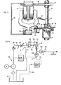
- Figures 6-8 illustrate an improved metering pump apparatus for delivering clean shots of lubricating fluid from a pressurized fluid reservoir to the lubricating nozzles.
- the improved metering pumping apparatus enables any air in the fluid supply line to be diverted back to the fluid reservoir and thus substantially prevents any air bubbles from entering the lubricating output lines to the lubricating nozzles.
- prior art problems due to the normal expansion of system components and of the lubricating fluid due to the normal "pumping action" of fluid solenoid valves used in the system, and due to the imperfect diverter valve aspect of such solenoid valves have been overcome.
- drippage of oil from the nozzles is substantially eliminated and the delivery of clean shots of metered amounts of lubricating fluid from the nozzles to the lubricating points on the chain is assured.
- FIG. 8 showing a hydraulic schematic diagram with the hydraulic lines interconnecting a base pumping station 92 connected to metering pump apparatus 94 which in turn is connected to a lubricating nozzle 96.
- Base station 92 incudes a conventional pump motor and supply pump, a relief valve for relieving excessive pressure, and a check valve supplying substantially constant pressure of about 211 kg/cm 2 (300 psi) - or typically in the range of 105-527 Kg/cm 2 (150-750 psi) - to the base station fluid output line .98.
- Line 98 is in turn connected to fluid line 60 at the input to the metering pump apparatus.
- the output of metering pumping apparatus 94 connects through fluid output lines 48 to the lubricating nozzles 44.
- the metering pump apparatus 94 includes means for diverting fluid in metering pump 54 at the end of a lubrication cycle to reservoir 96 via a return line 100.
- the metering pump apparatus includes a solenoid valve 56 and a metering pump 54 interconnected through two-way fluid line 102 for returning any fluid and air in the metering pump through a connecting fluid line 104 to the return line 100.
- Solenoid valve 56 is a commercially available three-way fluid valve which when actuated passes fluid from line 60 to the metering pump, and when deactivated or shuttled, connects fluid line 102 to line 104.
- valves inherently provide an undesired "pumping action" during shuttling which tends to force fluid into the metering pump thereby leading to dripping from nozzles.
- valves are imperfect diverter valves so that at an instantaneous point in time all three valve ports are undesirably interconnected which leads to fluid dripping from the nozzles. The present invention has eliminated these prior art problems.
- Pump body 54 includes check valves 106 and 108 as illustrated in Figure 8 and as will be more particularly described in connection with the structure shown in Figures 6 and 7.
- adjustment means 110 are provided on the metering pump to variably adjust the desired amount of lubricant supplied during each shot.
- Velocity control 58 is provided to adjust the velocity of the lubricant shot.
- Figure 7 illustrates pump body 54 as including a main body portion 112 and a manifold portion 114.
- Manifold 114 includes a central cavity 116 which communicates with return line 100 and also with fluid line 104 which in turn is connected to solenoid valve 56.
- fluid line 104 connects to a suitable opening or port around the perimeter of manifold 114, which port communicates with cavity 116 inside the manifold in a manner similar to that shown for the connection of fluid line 100 to the manifold.
- Metering pump body portion 112 includes a pump chamber 118 which communicates with passageway 120 through a ball check valve 106 to nozzle output line 48.
- Metering pump piston 124 is located for slidable action within cylinder-chamber 126 with the chamber in turn being connected to input line 60 from the base station supply pump through solenoid valve 56 and velocity flow control 58.
- Spring 128 biases piston 124 towards the right in Figure 7 until the right hand end of piston 124 abuts against the end of threaded adjustment screw 110.
- rotation of threaded screw 110 adjustably increases or decreases the volume within pumping chamber 118 which in turn adjustably controls the amount of lubricating fluid delivered during each lubricating operation.
- On the opposite side of chamber 118 there is provided a check valve 108 for controlling fluid communication between cavity 116 in manifold 114 and pumping chamber 118 such that the flow of fluid can only go from cavity 116 into cavity 118.
- metering pump apparatus 94 The following describes the operation of metering pump apparatus 94. Initially, the system is operated several times in order to eliminate any air in the lines and to prime pumping chamber 118 with lubricating fluid. Thus, initially, with each operation of solenoid valve 56, pressurized fluid is delivered from base station output 98 through line 60 and into chamber 126 to force piston 124 to the left in Figure 7 to initially expel air and any fluid through line 48. When the solenoid valve deactivates, spring 128 forces fluid in cylinder-chamber 126 upwardly through solenoid valve 56, line 104, cavity 116, check valve 108 and into pumping chamber 118.
Landscapes
- Engineering & Computer Science (AREA)
- General Engineering & Computer Science (AREA)
- Mechanical Engineering (AREA)
- General Details Of Gearings (AREA)
- Chair Legs, Seat Parts, And Backrests (AREA)
- Valve-Gear Or Valve Arrangements (AREA)
Applications Claiming Priority (2)
| Application Number | Priority Date | Filing Date | Title |
|---|---|---|---|
| US06/659,365 US4648486A (en) | 1984-10-10 | 1984-10-10 | Apparatus for lubricating a moving chain |
| US659365 | 1984-10-10 |
Publications (2)
| Publication Number | Publication Date |
|---|---|
| EP0178055A2 true EP0178055A2 (fr) | 1986-04-16 |
| EP0178055A3 EP0178055A3 (fr) | 1987-01-14 |
Family
ID=24645105
Family Applications (1)
| Application Number | Title | Priority Date | Filing Date |
|---|---|---|---|
| EP85305880A Withdrawn EP0178055A3 (fr) | 1984-10-10 | 1985-08-19 | Lubrificateur pour une chaíne d'entraínement |
Country Status (3)
| Country | Link |
|---|---|
| US (1) | US4648486A (fr) |
| EP (1) | EP0178055A3 (fr) |
| JP (1) | JPS6190909A (fr) |
Families Citing this family (37)
| Publication number | Priority date | Publication date | Assignee | Title |
|---|---|---|---|---|
| JPH0638209Y2 (ja) * | 1987-12-25 | 1994-10-05 | リューベ株式会社 | チェーン給油装置 |
| US4844203A (en) * | 1988-01-29 | 1989-07-04 | Patco Sales & Service, Inc. | Self contained conveyor lubricating apparatus |
| US5186280A (en) * | 1991-05-03 | 1993-02-16 | Mattcheck Donald L | High temperature oven conveyor chain lubrication system |
| US5285871A (en) * | 1992-08-17 | 1994-02-15 | Mechanical Tool & Engineering Co. | System for distributing viscous lubricant |
| US5322103A (en) * | 1992-11-23 | 1994-06-21 | Hudson Sales Corporation | Continuous chain saw lubricating system for use in a tree delimbing and topping machine |
| US5563392A (en) * | 1995-04-12 | 1996-10-08 | Patco Sales & Service, Inc. | Method and apparatus for monitoring wear of a continuous chain |
| BE1009665A3 (nl) * | 1995-10-04 | 1997-06-03 | Egemin Nv | Onderhoudsinrichting voor een sleepketting. |
| US5647456A (en) * | 1996-04-25 | 1997-07-15 | Gelb; Joseph | Chain lubricating system |
| US6053285A (en) * | 1998-01-14 | 2000-04-25 | G.P. Reeves, Inc. | Apparatus for dispensing measured quantities of lubricant |
| RU2194209C2 (ru) * | 1998-06-19 | 2002-12-10 | Иркутская государственная сельскохозяйственная академия | Устройство для подачи консистентной смазки |
| AU6280099A (en) * | 1998-10-06 | 2000-04-26 | Frost Links, Inc. | Lubricating device for conveyor systems |
| ES2288150T3 (es) * | 1999-07-22 | 2008-01-01 | Johnsondiversey, Inc. | Composicion lubricante para lubricar una cinta transportadora. |
| US6478115B1 (en) * | 2000-05-26 | 2002-11-12 | Oil-Rite Corporation | Overhead conveyor lubrication apparatus and method |
| US6585085B1 (en) * | 2000-05-30 | 2003-07-01 | Tranergy Corporation | Wayside wheel lubricator |
| US6576298B2 (en) * | 2000-09-07 | 2003-06-10 | Ecolab Inc. | Lubricant qualified for contact with a composition suitable for human consumption including a food, a conveyor lubrication method and an apparatus using droplets or a spray of liquid lubricant |
| US6688434B2 (en) | 2002-02-22 | 2004-02-10 | Ecolab Inc. | Conveyor and lubricating apparatus, lubricant dispensing device, and method for applying lubricant to conveyor |
| RU2219427C2 (ru) * | 2002-03-06 | 2003-12-20 | Георгиевское линейное производственное управление магистральных газопроводов Общество с ограниченной ответственностью "Кавказтрансгаз" | Нагнетатель для автоматической подачи уплотнительного и смазывающего материала |
| KR100617419B1 (ko) * | 2003-12-19 | 2006-08-30 | 오티스 엘리베이터 컴파니 | 저소음 체인이상감지장치 |
| DE202005016589U1 (de) * | 2005-05-06 | 2005-12-22 | Lincoln Gmbh & Co. Kg | Abschmiereinrichtung |
| US20060289237A1 (en) * | 2005-06-24 | 2006-12-28 | Beauchamp Shaun M | Lubricant Delivery Apparatus and Method |
| US20070137937A1 (en) * | 2005-11-29 | 2007-06-21 | Guillermo Citro | Conveyor lubricating apparatus |
| US8210318B2 (en) * | 2006-04-04 | 2012-07-03 | Haas Automation, Inc. | Minimum oil machining system |
| JP5374964B2 (ja) * | 2008-08-25 | 2013-12-25 | 澁谷工業株式会社 | 集合コンベヤ |
| US8181747B2 (en) * | 2008-10-29 | 2012-05-22 | Crestron Electronics Inc. | Bicycle chain cleaner and lubrication apparatus |
| US20110278324A1 (en) * | 2010-05-14 | 2011-11-17 | Michael Tony Kilian | Lubrication work center |
| US9079720B1 (en) * | 2010-07-02 | 2015-07-14 | Linear Market Technical Services Corporation | Roller chain lubricator |
| WO2012137393A1 (fr) * | 2011-04-04 | 2012-10-11 | 株式会社Ihi回転機械 | Unité de pompe à graisse |
| CN103889834B (zh) * | 2011-08-29 | 2017-07-14 | 3M创新有限公司 | 用于顺序清洁润滑驱动链尤其是摩托车链的装置 |
| EP2751467A4 (fr) | 2011-08-30 | 2015-05-13 | Stephania Holdings Inc | Procédés de commande d'un dispositif de lubrification, procédés de communication et dispositifs et systèmes |
| CN104329555B (zh) * | 2014-10-24 | 2017-02-15 | 安徽启光能源科技研究院有限公司 | 一种用于铆接设备的自动润滑系统及其润滑方法 |
| JP6502388B2 (ja) * | 2015-01-14 | 2019-04-17 | 株式会社Fuji | フィーダ保守装置及びフィーダ保守装置の制御方法 |
| US10307931B2 (en) * | 2015-07-24 | 2019-06-04 | The Research Foundation For Suny | Oil delivery system for the lubrication of a chainsaw |
| US10024494B2 (en) * | 2015-08-17 | 2018-07-17 | CanServ, LLC | Lubrication system and method of making the same |
| US9896276B2 (en) | 2016-01-26 | 2018-02-20 | Patco Sales and Services, Inc. | Method and apparatus for automatically and visually monitoring wear of a continuous chain |
| DE102017211308A1 (de) * | 2017-07-04 | 2019-01-10 | Aktiebolaget Skf | Schmiersystem für eine Rollenkette und Förderanordnung, die mit einem solchen Schmiersystem ausgestattet ist |
| CN215370034U (zh) * | 2021-08-30 | 2021-12-31 | 烟台杰瑞石油装备技术有限公司 | 安装支架和辅助机构 |
| CA221424S (en) | 2023-05-12 | 2024-08-13 | A T S Electro Lube Int Inc | Lubricant applicator |
Family Cites Families (13)
| Publication number | Priority date | Publication date | Assignee | Title |
|---|---|---|---|---|
| US3031033A (en) * | 1960-03-11 | 1962-04-24 | King Ltd Geo W | Lubrication of conveyors |
| US3116810A (en) * | 1961-10-17 | 1964-01-07 | Gene R Olson | Lubricating devices |
| US3599753A (en) * | 1969-07-14 | 1971-08-17 | Warren J Walsh | Conveyor roller lubricating device |
| US3869023A (en) * | 1973-01-22 | 1975-03-04 | Madison Kipp Corp | Mechanical lubricating device and method |
| FI52141C (fi) * | 1973-08-16 | 1977-06-10 | Safematic Ltd Oy | Keskusvoitelujärjestelmän annostelulaite. |
| GB1415820A (en) * | 1974-06-25 | 1975-11-26 | Madison Kipp Corp | Lubricating device for a chain conveyor |
| US4085821A (en) * | 1976-09-07 | 1978-04-25 | Madison-Kipp Corporation | Lubrication system |
| DE2750037A1 (de) * | 1977-11-09 | 1979-05-10 | Volkswagenwerk Ag | Einrichtung zur schmierung einer kette |
| US4271930A (en) * | 1978-05-05 | 1981-06-09 | Madison-Kipp Corporation | Enclosed lubricating apparatus |
| SE448158B (sv) * | 1980-10-17 | 1987-01-26 | Bohlin E Ab | Anordning for smorjning av reler |
| US4444292A (en) * | 1981-08-12 | 1984-04-24 | Standard Oil Company (Indiana) | Method and apparatus for lubricating a machine |
| GB2104163B (en) * | 1981-08-22 | 1985-03-13 | Cyril Douglas Lister | Oil shot lubricator |
| US4506763A (en) * | 1982-06-18 | 1985-03-26 | Conveyor Maintenance & Supply, Inc. | Conveyor and/or chain lubrication apparatus |
-
1984
- 1984-10-10 US US06/659,365 patent/US4648486A/en not_active Expired - Fee Related
-
1985
- 1985-08-19 EP EP85305880A patent/EP0178055A3/fr not_active Withdrawn
- 1985-10-07 JP JP60224624A patent/JPS6190909A/ja active Pending
Also Published As
| Publication number | Publication date |
|---|---|
| US4648486A (en) | 1987-03-10 |
| EP0178055A3 (fr) | 1987-01-14 |
| JPS6190909A (ja) | 1986-05-09 |
Similar Documents
| Publication | Publication Date | Title |
|---|---|---|
| US4648486A (en) | Apparatus for lubricating a moving chain | |
| US5181585A (en) | Lubricating device for supplying several lubricating points, in particular of a knitting machine, with lubricant, preferably oil, and method | |
| US7007773B2 (en) | Lubrication device | |
| US4520902A (en) | Lubricant applying system and injector means | |
| US5533432A (en) | Saw assembly | |
| US3116810A (en) | Lubricating devices | |
| US4679659A (en) | Method and apparatus for lubricating a moving chain | |
| US4024930A (en) | Lubricating device and method | |
| US4630712A (en) | Automatic chain lubricating system | |
| US2664969A (en) | Machine lubricator | |
| FR2406144A1 (fr) | Operateur de vanne a commande electro-hydraulique | |
| US3684059A (en) | Chain lubricating apparatus | |
| US3869023A (en) | Mechanical lubricating device and method | |
| US2848068A (en) | Conveyor lubricator | |
| JPS6118078B2 (fr) | ||
| US6085869A (en) | Combined oil and grease system | |
| JPH07502936A (ja) | 電気流体圧式制御装置及び減圧弁 | |
| US2594039A (en) | Apparatus for dispensing lubricant to the wheels or rollers of chain conveyers | |
| EP0063446A1 (fr) | Appareil pour diriger un liquide lubrifiant sous pression vers une chaine en mouvement | |
| RU2035623C1 (ru) | Регулятор подачи аксиально-поршневого насоса | |
| US3595341A (en) | Low pressure pneumatic motor lubricating system | |
| GB1451161A (en) | Pressurised fluid driven vibrator | |
| JP4049872B2 (ja) | タイミング式自動給油装置 | |
| EP0128814A1 (fr) | Dispositif hydraulique d'un tapis transporteur de produits dans un tunnel de congélation | |
| US3446314A (en) | Conveyor trolley wheel lubricator |
Legal Events
| Date | Code | Title | Description |
|---|---|---|---|
| PUAI | Public reference made under article 153(3) epc to a published international application that has entered the european phase |
Free format text: ORIGINAL CODE: 0009012 |
|
| AK | Designated contracting states |
Kind code of ref document: A2 Designated state(s): DE FR GB IT |
|
| PUAL | Search report despatched |
Free format text: ORIGINAL CODE: 0009013 |
|
| AK | Designated contracting states |
Kind code of ref document: A3 Designated state(s): DE FR GB IT |
|
| 17P | Request for examination filed |
Effective date: 19870710 |
|
| 17Q | First examination report despatched |
Effective date: 19880825 |
|
| STAA | Information on the status of an ep patent application or granted ep patent |
Free format text: STATUS: THE APPLICATION IS DEEMED TO BE WITHDRAWN |
|
| 18D | Application deemed to be withdrawn |
Effective date: 19890105 |
|
| RIN1 | Information on inventor provided before grant (corrected) |
Inventor name: KAYSER, JOHN P. Inventor name: KAST, PHILIP J. |