EP0178102A2 - Assemblages de bornes électriques et de connecteurs - Google Patents
Assemblages de bornes électriques et de connecteurs Download PDFInfo
- Publication number
- EP0178102A2 EP0178102A2 EP85306947A EP85306947A EP0178102A2 EP 0178102 A2 EP0178102 A2 EP 0178102A2 EP 85306947 A EP85306947 A EP 85306947A EP 85306947 A EP85306947 A EP 85306947A EP 0178102 A2 EP0178102 A2 EP 0178102A2
- Authority
- EP
- European Patent Office
- Prior art keywords
- terminal
- male terminal
- female
- slit
- male
- Prior art date
- Legal status (The legal status is an assumption and is not a legal conclusion. Google has not performed a legal analysis and makes no representation as to the accuracy of the status listed.)
- Granted
Links
- 230000000712 assembly Effects 0.000 title description 6
- 238000000429 assembly Methods 0.000 title description 6
- 239000002184 metal Substances 0.000 claims description 12
- 230000037431 insertion Effects 0.000 claims description 10
- 238000003780 insertion Methods 0.000 claims description 10
- 230000013011 mating Effects 0.000 claims description 4
- RTZKZFJDLAIYFH-UHFFFAOYSA-N Diethyl ether Chemical compound CCOCC RTZKZFJDLAIYFH-UHFFFAOYSA-N 0.000 claims 2
- 238000010276 construction Methods 0.000 description 3
- 238000005452 bending Methods 0.000 description 2
- 230000007812 deficiency Effects 0.000 description 1
- 239000000463 material Substances 0.000 description 1
- 230000035515 penetration Effects 0.000 description 1
- 230000000284 resting effect Effects 0.000 description 1
Images


Classifications
-
- H—ELECTRICITY
- H01—ELECTRIC ELEMENTS
- H01R—ELECTRICALLY-CONDUCTIVE CONNECTIONS; STRUCTURAL ASSOCIATIONS OF A PLURALITY OF MUTUALLY-INSULATED ELECTRICAL CONNECTING ELEMENTS; COUPLING DEVICES; CURRENT COLLECTORS
- H01R13/00—Details of coupling devices of the kinds covered by groups H01R12/70 or H01R24/00 - H01R33/00
- H01R13/02—Contact members
- H01R13/10—Sockets for co-operation with pins or blades
- H01R13/11—Resilient sockets
- H01R13/114—Resilient sockets co-operating with pins or blades having a square transverse section
-
- H—ELECTRICITY
- H01—ELECTRIC ELEMENTS
- H01R—ELECTRICALLY-CONDUCTIVE CONNECTIONS; STRUCTURAL ASSOCIATIONS OF A PLURALITY OF MUTUALLY-INSULATED ELECTRICAL CONNECTING ELEMENTS; COUPLING DEVICES; CURRENT COLLECTORS
- H01R13/00—Details of coupling devices of the kinds covered by groups H01R12/70 or H01R24/00 - H01R33/00
- H01R13/02—Contact members
- H01R13/04—Pins or blades for co-operation with sockets
- H01R13/05—Resilient pins or blades
- H01R13/057—Resilient pins or blades co-operating with sockets having a square transverse section
-
- H—ELECTRICITY
- H01—ELECTRIC ELEMENTS
- H01R—ELECTRICALLY-CONDUCTIVE CONNECTIONS; STRUCTURAL ASSOCIATIONS OF A PLURALITY OF MUTUALLY-INSULATED ELECTRICAL CONNECTING ELEMENTS; COUPLING DEVICES; CURRENT COLLECTORS
- H01R13/00—Details of coupling devices of the kinds covered by groups H01R12/70 or H01R24/00 - H01R33/00
- H01R13/40—Securing contact members in or to a base or case; Insulating of contact members
- H01R13/42—Securing in a demountable manner
- H01R13/428—Securing in a demountable manner by resilient locking means on the contact members; by locking means on resilient contact members
- H01R13/432—Securing in a demountable manner by resilient locking means on the contact members; by locking means on resilient contact members by stamped-out resilient tongue snapping behind shoulder in base or case
Definitions
- the present invention relates to electrical terminals and connector assemblies.
- Terminals disclosing retaining dimples or elongated flutes are disclosed in US-A-3,370,265 and US-A-3,406,376.
- Female contacts having inwardly extending contact bights are found in the following U.S. patents: US-A-3,426,320; US-A-4,076,369; and US-A-4,128,293.
- Retaining lances to hold a box terminal within a housing are disclosed in US-A-4,015,891 and US-A-4,342,495.
- a female terminal having a stop shoulder to prevent overinsertion of a contact is disclosed in US-A-3,998,518.
- the present invention includes new and improved male and female electrical terminals shaped to interconnect to establish electrical connection therebetween and a new and improved electrical connector assembly including the electrical terminals.
- the invention also includes the electrical terminals each mounted within an insulative housing such that the housings may be telescopically interconnected to establish electrical connection between the terminals.
- an electrical connector assembly includes an elongated, electrically conductive female terminal formed from metal wherein the female terminal comprises a front end shaped.to receive, in electrical connection therewith, a male terminal, said front end including a plurality of walls defining a male terminal-receiving opening, including a first wall portion defining a first slit therein and a second wall portion defining a second slit therein, said slits extending toward a rear end of the female terminal to provide resiliency to said wall portions for expansion of said opening when a male terminal is received in said male terminal-receiving opening.
- the first slit may extend a greater distance toward the rear end than the second slit so that the first wall portion has a greater resiliency than the second wall portion.
- the lateral projections may extend inwardly to a greater extent at a location nearer the first slit than at a location nearer the second slit to compensate for the greater resiliency in the first wall portion to achieve substantially uniform electrical contact pressure at symmetrical contact area portions of opposed projections.
- the rear end of the female terminal may be adapted for electrical connection to another circuit element, an intermediate portion of the female terminal electrically connecting the front end to the rear end.
- the male terminal may include a front end cooperatively shaped to fit within the male terminal-receiving opening of the female terminal and may have opposed walls shaped for relatively high pressure electrical contact against the lateral projections of said female terminal.
- the female terminal may be formed from flat metal having longitudinal end walls and the flat metal may be formed or bent to dispose the end walls in close proximity to each other, thereby forming the first slit defined by a seam or gap between the longitudinal end walls and to form the male terminal-receiving opening at the front end of the female terminal.
- the second slit or gap of the female terminal may be disposed in vertical or horizontal alignment with the first slit or gap to achieve a symmetrical flexing action of the resilient walls of the female terminal.
- the male terminal may include a tapered front end for easier insertion into the female terminal, including female contact wall portions bent toward each other in a V-shape at the front end of the male terminal.
- the front end of the male terminal may include a plow wall curved upwardly from a lower front end wall of the male terminal.
- the electrical connector assembly may include a female, electrically conductive terminal disposed within a first insulative housing and a male, electrically conductive terminal disposed within.a second insulative housing, the first insulative housing having a mating portion surrounding a male terminal-receiving opening in a front end of the female terminal and the second insulative housing having a mating portion surrounding a front end of the male terminal.
- the front end of the male terminal may be adapted to be received within the male terminal-receiving opening of the female terminal and the first and second insulative housings may be shaped such that one of the insulative housings is telescopically received within the other insulative housing for electrical connection of the male terminal within the female terminal.
- a female terminal includes a first wall portion defining a first slit therein and a second wall portion defining a second slit therein, the slits extending toward a rear end of the female terminal to provide resiliency to the slit wall portions for expansion of the female opening when a male terminal is received therein.
- the first slit may extend a greater distance toward the rear end than the second slit so that the first wall portion has a greater resiliency than the second wall portion.
- the lateral projections may extend inwardly to a greater extent at a location nearer the first slit than at a location nearer the second slit to compensate for the greater resiliency in the first wall portion to achieve substantially uniform electrical contact pressure at symmetrical contact area portions of opposed projections.
- the male terminal may be generally U-shaped and adapted to fit within the female terminal such that the base of the U is adjacent the second slit and the legs of the U are in contact with the laterally extending projections of the female terminal.
- the male and female terminals may be shaped cooperatively to an inner shape of the male and female insulative housings to lock the terminals in proper position within the housings.
- the first insulative housing may include a pair of inner surface stop shoulders for contact against the stop tabs when the female terminal is inserted sufficiently to lock the locking lances against the first housing inner locking surfaces.
- the female terminal may further include a plurality of alignment dimples extending into the male terminal-receiving cavity of the female terminal to maintain alignment between the male terminal and the female terminal.
- the male terminal may include a plurality of spring biased locking lances and its insulative housing (the second housing) may include inner locking surfaces defining shoulders thereon adapted to lock the male terminal locking lances thereagainst when the male terminal is inserted a sufficient distance into the second housing.
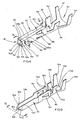
- the electrical connector assembly 10 (Fig. 1) includes one or more insulative housings 12, 14, 16 and 18, surrounding one or more electrically conductive female terminals 20 (Fig. 4) forming one or more female terminal assemblies generally designated 21, and one or more insulative housings 22, 24, 26 and 28 surrounding one or more male terminals 30 (Fig. 9) forming one or more male terminal assemblies generally designated 131.
- the housings 12, 14, 16 and 18 surrounding the female terminals 20 are keyed or shaped so that the housings 12, 14, 16 and 18 can be telescopically joined with the housings 22, 24, 26 and 28 surrounding the male terminals 30 only in one way (as shown in Fig. 1) to prevent electrical connection between incorrect male and female terminals.
- the female terminal 20 is cut and formed or bent from a flat sheet of metal stock, and is formed to provide a male terminal-receiving front end, generally designated 32, in a generally rectangular shape.
- the female terminal 20 also includes a rear end, generally designated 34, including a pair of electrically conductive bendable tabs 36 and 38 surrounding a wire receiving lower channel 40 adapted to be bent or clinched over a bare wire or other circuit element disposed within the wire receiving channel 40.
- the rear end 34 of the female terminal 20 also includes a second pair of bendable tabs 42 and 44 adapted to be bent or clinched onto an insulated portion 45 (Fig. 13) of the wire in channel 40 to provide a stress relief for the wire as well known in the art.
- An opposite or lower wall portion, generally designated 52, of the terminal-receiving housing 31 also includes a seam or slit 54 aligned with the seam or slit 46.
- the terminal receiving housing 31 comprises a reduced cross-sectional area portion 56 (Fig. 5) at the front end 32 and an enlarged cross-sectional area portion 58 having a rounded lower wall 60 extending from and integral with a rearward portion of side walls 62 and 64.
- the upper, longer slit or seam 46 and the lower, shorter seam or slit 54 provide some resiliency to upper and lower walls 66 and 68 so that less insertion force is necessary to mate the male terminal 30 within the female terminal 20, while providing high pressure electrical contact as will be described in more detail hereinafter.
- the elongated contact surfaces 70 and 72 extending inwardly from sidewalls 62 and 64 are centrally aligned within the female terminal cavity such that an uppermost male terminal-contact surface portion 78 (closest to the longer slit 46) of each projection 70 and 72 is spaced a shorter distance than the lowermost male terminal-contact surface portion 80 (closest to shorter slit or seam 54) of each inwardly extending lateral projection 70 and 72.
- the uppermost contact surface portions 78 of the projections 70 and 72 are closer together than the lowermost contact surface portion 80 since the terminal-receiving housing 31 is more reslient at the upper wall 51 than at the lower wall 52.
- the distance between the two uppermost male terminal contact surface portions 78 is about 2% to about 10% shorter than the distance between the lowermost male terminal contact surface portions 80 so that the pressure of the uppermost contact surface portion 78 and the lowermost contact surface portions 80 against the male terminal 30 will be approximately the same.
- the uppermost male terminal contact surface portions 78 are closer together than the lowermost male terminal contact surface portions 80 to take into account the greater resiliency of the upper portion of the female terminal 20 because of the greater dimension of the seam or slit 46 extending completely across the upper wall 66 defining an upper portion of the male terminal receiving cavity 31.
- the male terminal 30 is more resilient toward an uppermost portion of tne contacting side walls since the male terminal 30 does not have an upper structural wall.
- the difference in dimensions between the uppermost contact surface portions 78 and the lowermost contact surface portions 80 can be varied depending upon the thickness of the female terminal walls 62, 64, 66, and 68; the difference in the length of upper and lower slits 46 and 54; and the outer dimensions of the male terminal 30 with respect to the inner dimensions of the male terminal-receiving cavity 31 of the female terminal 20.
- the female terminal 20 can have varied cross sectional shapes while providing contact - force - equalizing lateral projections.
- the seam or slit 54 in the lower wall 68 extends from the front end 32 of the female terminal 20 toward the rear end 34 of the female terminal 20 but does not extend completely across the male terminal receiving cavity 31.
- the female terminal 20 is formed or bent from flat metal to provide the lower wall 68 extending from the front end 32 about 1/3 to 1/2 of the distance of the length of the male terminal receiving cavity 31.
- the lower wall 68 is formed to be integral with the curved or rounded lower wall 60 to form a larger or enlarged cross sectional area rearward portion of the male terminal receiving cavity 31 of the female terminal 20.
- the curved or rounded lower wall 60 is formed integral with the sidewalls 62 and 64 of the female terminal and acts as a spring to resiliently bias upper wall halves 66a and 66b together and to bias lower wall half portions 52a and 52b together and permits the upper wall halves 66a and 66 b to be separated, slightly arcuately, when the male terminal 30 is forced into the female terminal 20 against the spring bias provided by the curved or rounded lower wall 60 to equalize the forces against the male terminal 30 by the uppermost and lowermost male terminal- contact surface portion 78 and 80 of the lateral projections 70 and 72.
- end surfaces 88 on the locking lances 82 and the stop surfaces 90 on the upwardly extending stop tabs 84 enables the stop surfaces 90 to be positioned against inner shoulders 92 on the interior of the female housing 12 at the same time that the end surfaces 88 of the locking lances 82 are expanded outwardly to rest against the shoulders 86 on the interior of the housing 12 and bottom stopper 93 engages shoulder 95 to lock the female terminal in position within the housing 12.
- the female terminal 20 includes one or more alignment dimples 107 in longitudinal alignment with the laterally extending projections 70 or 72 in the sidewalls 62 and 64 and spaced therefrom to maintain alignment of the male terminal 30 within the female terminal 20 so that the male terminal 30 does not fit closer to either sidewall 62 or 64 but is maintained in central longitudinal alignment within the female terminal 20.
- the female terminal 20, at the front end 32 can be formed having slits 106 and 108 in sidewalls 62 and 64 extending toward the rear end 34 of the female terminal and ending at the laterally extending projections.
- two distinct and sharply pointed laterally extending projections 110 and 112 are formed in sidewall 62 and two distinct, sharply pointed laterally extending projections 114 and 116 are formed in sidewall 64 to provide high pressure contact of the points 11 8 , 120, 122 and 124 against the male terminal 30. Similar to the construction shown in Fig.
- Fig. 8 another embodiment is shown for the female terminal 20 cross-sectional shape in the form of a continuous, curved or tubular structure, for example, in the shape of an ellipse.
- lateral projections can be formed in the sides of the ellipse in alignment across the widest diameter of the ellipse either in the shape of the bar type projections, described with reference to numerals 70 and 72 in Fig. 6, or in the form of the sharply pointed multiple projections as described with reference to reference numerals 118, 120, 122 and 124 in Fig. 7.
- Fig. 8 another embodiment is shown for the female terminal 20 cross-sectional shape in the form of a continuous, curved or tubular structure, for example, in the shape of an ellipse.
- lateral projections can be formed in the sides of the ellipse in alignment across the widest diameter of the ellipse either in the shape of the bar type projections, described with reference to numerals 70 and 72 in Fig. 6, or in
- the widest dimension of the ellipse is formed having side slots 126 and 128 forming two sharply pointed laterally extending projections 130 and 132 along one side of the ellipse and two sharply pointed laterally extending projections 134 and 136 in an opposite side of the ellipse such that projections 130 and 134 are in horizontal alignment and projections 132 and 136 are in horizontal alignment.
- the distance between projections 130 and 134 is less than the distance between projections 132 and 136 to compensate for the greater resiliency at the top of the ellipse than at the bottom of the ellipse because of the difference in the lengths of the slits 46 and 54.
- the male terminal 30, like the female terminal 20 is formed from flat metal stock including two upwardly turned sidewalls 138 and 140 integral with a lower or bottom wall" 142 to form a generally U-shaped male terminal dimensioned to fit within the cavity 31 of the female terminal 20.
- the sidewalls 138 and 140 include outer surfaces 144 and 146, respectively, for electrical connection to the inwardly extending lateral projections 70 and 72 in the female terminal 20.
- the male terminal 30 includes electrically conductive bendable tabs 148 and 150 for bending or clinching against a bare wire inserted within a wire receiving lower channel 152 and a second pair of bendable tabs 154 and 156 at a rear end 158 of the male terminal 30 to be bent or clinched around an insulated portion of the wire resting within the wire receiving lower channel 152 to act as a stress relief to prevent the disengagement of the wire from the electrically conductive clinched tabs 148 and 150.
- a front end 160 of the male terminal 30 is formed in a V-shaped wedge by bending the sidewalls 138 and 140 at the front end 160 toward each other to form a generally V-shaped front or insertion end 160 of the male terminal 30. Further, the lower wall 142 is bent to curve upwardly in a smooth arc to form a lower plow member 162 (Fig. 10) so that the lower surface 142 of the male terminal does not have any sharp edges which might make more difficult the insertion of the male terminal 30 into the female terminal 20.
- electrical connection between the male terminal 30 and the female terminal 20 can be made with relatively low insertion forces while providing a relatively high pressure electrical contact between the male terminal 30 and the female terminal 20 due to the sharp contacts and resilient terminals.
- the front end 160 of the male terminal 30 includes two curved, converging nose sections 164 and 166 integral with the sidewalls 138 and 140 bent toward each other and each shaped as a longitudinal section of a truncated cone with the smallest diameter cone section nearest the front end 1.60 of the male terminal 30.
- the nose sections 164 and 166 and the plow member 162 in combination forming the front end 160 of the male terminal 30, can be easily inserted within the terminal receiving cavity 31 of the female terminal 20 without interference from minor inner surface imperfections of the female terminal walls 62, 64, 66 and 68.
- the nose sections 164 and 166 provide sloped external surfaces 168 and 170 for initial contact against the lateral extending projections 70 and 72 within the female terminal 20 to minimize the force necessary to insert the male terminal 30 within the female terminal 20 to establish electrical connection therebetween.
Landscapes
- Connector Housings Or Holding Contact Members (AREA)
- Details Of Connecting Devices For Male And Female Coupling (AREA)
- Cable Accessories (AREA)
Applications Claiming Priority (2)
| Application Number | Priority Date | Filing Date | Title |
|---|---|---|---|
| JP59213235A JPS6191884A (ja) | 1984-10-11 | 1984-10-11 | 電気コネクタ装置 |
| JP213235/84 | 1984-10-11 |
Publications (3)
| Publication Number | Publication Date |
|---|---|
| EP0178102A2 true EP0178102A2 (fr) | 1986-04-16 |
| EP0178102A3 EP0178102A3 (en) | 1987-10-28 |
| EP0178102B1 EP0178102B1 (fr) | 1991-05-08 |
Family
ID=16635760
Family Applications (1)
| Application Number | Title | Priority Date | Filing Date |
|---|---|---|---|
| EP85306947A Expired EP0178102B1 (fr) | 1984-10-11 | 1985-09-30 | Assemblages de bornes électriques et de connecteurs |
Country Status (6)
| Country | Link |
|---|---|
| US (1) | US4681393A (fr) |
| EP (1) | EP0178102B1 (fr) |
| JP (1) | JPS6191884A (fr) |
| CA (1) | CA1237498A (fr) |
| DE (1) | DE3582775D1 (fr) |
| SG (1) | SG33192G (fr) |
Cited By (8)
| Publication number | Priority date | Publication date | Assignee | Title |
|---|---|---|---|---|
| EP0263610A3 (en) * | 1986-10-08 | 1989-03-08 | Interlock Corporation | Tab receptacle terminal having improved electrical and mechanical features |
| EP0443774A1 (fr) * | 1990-02-21 | 1991-08-28 | Molex Incorporated | Connecteur électrique et borne |
| EP0380337A3 (fr) * | 1989-01-25 | 1991-11-13 | THOMAS & BETTS CORPORATION | Connecteur |
| EP0551085A1 (fr) * | 1992-01-10 | 1993-07-14 | Molex Incorporated | Connecteur électrique avec des moyens contre les surcontraintes |
| EP0545529A3 (en) * | 1991-11-30 | 1993-08-18 | Nec Corporation | Electrical connector |
| EP0708494A3 (fr) * | 1994-10-17 | 1996-06-05 | Molex Inc | |
| EP0738028A1 (fr) * | 1995-04-10 | 1996-10-16 | Siemens Aktiengesellschaft | Fiche plate |
| WO2013012887A3 (fr) * | 2011-07-19 | 2013-04-18 | Molex Incorporated | Borne et connecteur électrique équipé de cette dernière |
Families Citing this family (10)
| Publication number | Priority date | Publication date | Assignee | Title |
|---|---|---|---|---|
| US4874338A (en) * | 1987-03-31 | 1989-10-17 | Amp Incorporated | Receptacle box terminal with improved contact area |
| US5221211A (en) * | 1989-09-12 | 1993-06-22 | The United States Of America As Represented By The United States Department Of Energy | Electrical receptacle |
| US5437567A (en) * | 1993-08-09 | 1995-08-01 | Molex Incorporated | Female electrical terminal |
| US5997363A (en) * | 1996-12-18 | 1999-12-07 | The Whitaker Corporation | Single piece electrical terminal for sealed connectors |
| JPH10247545A (ja) * | 1997-03-03 | 1998-09-14 | Sumitomo Wiring Syst Ltd | 圧接コネクタ |
| ES1039053Y (es) * | 1997-12-17 | 1999-03-16 | Mecanismos Aux Ind | Terminal hembra perfeccionado. |
| US6918798B2 (en) * | 2003-07-15 | 2005-07-19 | Molex Incorporated | Female terminal with flexible sidewalls and flat angled contacts |
| CN202772303U (zh) * | 2012-09-04 | 2013-03-06 | 泰科电子(上海)有限公司 | 电连接器和电连接器组件 |
| JP6569140B2 (ja) * | 2016-05-18 | 2019-09-04 | 住友電装株式会社 | 雌端子金具 |
| CN110896179B (zh) | 2018-09-13 | 2021-03-30 | 上海莫仕连接器有限公司 | 导电端子 |
Family Cites Families (16)
| Publication number | Priority date | Publication date | Assignee | Title |
|---|---|---|---|---|
| US2907976A (en) * | 1956-07-27 | 1959-10-06 | Raytheon Co | Electrical connectors and contacts therefor |
| US2955178A (en) * | 1958-06-12 | 1960-10-04 | Gen Motors Corp | Fuse panel assembly |
| DE1465259A1 (de) * | 1964-02-22 | 1969-02-13 | Bosch Gmbh Robert | Loesbare elektrische Steckverbindung |
| NL134805C (fr) * | 1965-11-09 | |||
| US3370265A (en) * | 1966-05-09 | 1968-02-20 | Berg Electronics Inc | Electrical connector |
| US3406376A (en) * | 1966-09-26 | 1968-10-15 | Itt | Socket contact and method of manufacture |
| US3783440A (en) * | 1971-06-02 | 1974-01-01 | Kanto Seiki Co | Electrical connector |
| US3998518A (en) * | 1972-04-04 | 1976-12-21 | Bunker Ramo Corporation | Electrical connector having improved releasable contact construction |
| US3894785A (en) * | 1972-04-18 | 1975-07-15 | Bunker Ramo | Connector |
| JPS5029116U (fr) * | 1973-07-12 | 1975-04-02 | ||
| GB1509201A (en) * | 1974-05-01 | 1978-05-04 | Rists Wires & Cables Ltd | Electrical connector |
| JPS5229272U (fr) * | 1975-08-19 | 1977-03-01 | ||
| US4076369A (en) * | 1976-07-26 | 1978-02-28 | Northern Telecom Limited | Box terminal for card edge receptacles in telecommunications systems and the like |
| JPS57148784U (fr) * | 1981-03-16 | 1982-09-18 | ||
| US4431256A (en) * | 1981-11-03 | 1984-02-14 | The Bendix Corporation | Split sleeve socket contact |
| US4493527A (en) * | 1982-09-30 | 1985-01-15 | The Bendix Corporation | Socket contact for electrical connectors |
-
1984
- 1984-10-11 JP JP59213235A patent/JPS6191884A/ja active Pending
-
1985
- 1985-09-09 US US06/773,952 patent/US4681393A/en not_active Expired - Lifetime
- 1985-09-27 CA CA000491719A patent/CA1237498A/fr not_active Expired
- 1985-09-30 DE DE8585306947T patent/DE3582775D1/de not_active Expired - Lifetime
- 1985-09-30 EP EP85306947A patent/EP0178102B1/fr not_active Expired
-
1992
- 1992-03-19 SG SG331/92A patent/SG33192G/en unknown
Cited By (8)
| Publication number | Priority date | Publication date | Assignee | Title |
|---|---|---|---|---|
| EP0263610A3 (en) * | 1986-10-08 | 1989-03-08 | Interlock Corporation | Tab receptacle terminal having improved electrical and mechanical features |
| EP0380337A3 (fr) * | 1989-01-25 | 1991-11-13 | THOMAS & BETTS CORPORATION | Connecteur |
| EP0443774A1 (fr) * | 1990-02-21 | 1991-08-28 | Molex Incorporated | Connecteur électrique et borne |
| EP0545529A3 (en) * | 1991-11-30 | 1993-08-18 | Nec Corporation | Electrical connector |
| EP0551085A1 (fr) * | 1992-01-10 | 1993-07-14 | Molex Incorporated | Connecteur électrique avec des moyens contre les surcontraintes |
| EP0708494A3 (fr) * | 1994-10-17 | 1996-06-05 | Molex Inc | |
| EP0738028A1 (fr) * | 1995-04-10 | 1996-10-16 | Siemens Aktiengesellschaft | Fiche plate |
| WO2013012887A3 (fr) * | 2011-07-19 | 2013-04-18 | Molex Incorporated | Borne et connecteur électrique équipé de cette dernière |
Also Published As
| Publication number | Publication date |
|---|---|
| EP0178102A3 (en) | 1987-10-28 |
| SG33192G (en) | 1992-05-22 |
| US4681393A (en) | 1987-07-21 |
| JPS6191884A (ja) | 1986-05-09 |
| EP0178102B1 (fr) | 1991-05-08 |
| DE3582775D1 (de) | 1991-06-13 |
| CA1237498A (fr) | 1988-05-31 |
Similar Documents
| Publication | Publication Date | Title |
|---|---|---|
| EP0178102B1 (fr) | Assemblages de bornes électriques et de connecteurs | |
| EP0390865B1 (fr) | Borne de prise de courant electrique | |
| EP0547396B1 (fr) | Borne électrique avec des moyens de rétention améliorés | |
| US5188545A (en) | Electrical socket terminal | |
| US5064391A (en) | Asymmetrical high density contact retention | |
| US4560231A (en) | Electrical connector | |
| US5839925A (en) | Electrical receptacle terminals | |
| EP0163375A2 (fr) | Connecteur électrique | |
| EP0760540A2 (fr) | Connecteur électrique avec des moyens améliorés de positionnement de cosses | |
| US7014515B2 (en) | Female terminal for a flat male terminal | |
| EP0935827B1 (fr) | Contact avec verrou pour la retenue du contact et logement adapte | |
| EP0279508A1 (fr) | Borne électrique | |
| US5067913A (en) | Electrical connector | |
| US20090075530A1 (en) | Electrical connector assembly | |
| EP0321285A1 (fr) | Borne bidirectionnelle, pour contacts électriques, à déplacement de l'isolation | |
| US5746620A (en) | Electrical connector including means for terminating wires | |
| JPH0371741B2 (fr) | ||
| EP0372767B1 (fr) | Contact électrique miniature à déplacement d'isolation | |
| US3842391A (en) | Electrical connector tab receptacle | |
| US4664460A (en) | Electrical connectors | |
| US4895532A (en) | Modular connector coupler with selective commoning system | |
| EP0638959B1 (fr) | Borne électrique femelle | |
| EP0775374A1 (fr) | Connecteur pour cable electrique | |
| US5015200A (en) | Connector with double acting latch | |
| EP0101290B1 (fr) | Connecteur à déplacement d'isolation à plusieurs calibres et contacts à cet effet |
Legal Events
| Date | Code | Title | Description |
|---|---|---|---|
| PUAI | Public reference made under article 153(3) epc to a published international application that has entered the european phase |
Free format text: ORIGINAL CODE: 0009012 |
|
| AK | Designated contracting states |
Kind code of ref document: A2 Designated state(s): CH DE FR GB IT LI NL |
|
| PUAL | Search report despatched |
Free format text: ORIGINAL CODE: 0009013 |
|
| RHK1 | Main classification (correction) |
Ipc: H01R 13/115 |
|
| AK | Designated contracting states |
Kind code of ref document: A3 Designated state(s): CH DE FR GB IT LI NL |
|
| 17P | Request for examination filed |
Effective date: 19871117 |
|
| 17Q | First examination report despatched |
Effective date: 19891030 |
|
| GRAA | (expected) grant |
Free format text: ORIGINAL CODE: 0009210 |
|
| AK | Designated contracting states |
Kind code of ref document: B1 Designated state(s): CH DE FR GB IT LI NL |
|
| ITF | It: translation for a ep patent filed | ||
| ET | Fr: translation filed | ||
| REF | Corresponds to: |
Ref document number: 3582775 Country of ref document: DE Date of ref document: 19910613 |
|
| PLBE | No opposition filed within time limit |
Free format text: ORIGINAL CODE: 0009261 |
|
| STAA | Information on the status of an ep patent application or granted ep patent |
Free format text: STATUS: NO OPPOSITION FILED WITHIN TIME LIMIT |
|
| 26N | No opposition filed | ||
| PGFP | Annual fee paid to national office [announced via postgrant information from national office to epo] |
Ref country code: NL Payment date: 19980623 Year of fee payment: 14 |
|
| PGFP | Annual fee paid to national office [announced via postgrant information from national office to epo] |
Ref country code: GB Payment date: 19980806 Year of fee payment: 14 |
|
| PGFP | Annual fee paid to national office [announced via postgrant information from national office to epo] |
Ref country code: FR Payment date: 19980902 Year of fee payment: 14 |
|
| PGFP | Annual fee paid to national office [announced via postgrant information from national office to epo] |
Ref country code: DE Payment date: 19980928 Year of fee payment: 14 |
|
| PGFP | Annual fee paid to national office [announced via postgrant information from national office to epo] |
Ref country code: CH Payment date: 19981005 Year of fee payment: 14 |
|
| PG25 | Lapsed in a contracting state [announced via postgrant information from national office to epo] |
Ref country code: LI Free format text: LAPSE BECAUSE OF NON-PAYMENT OF DUE FEES Effective date: 19990930 Ref country code: GB Free format text: LAPSE BECAUSE OF NON-PAYMENT OF DUE FEES Effective date: 19990930 Ref country code: CH Free format text: LAPSE BECAUSE OF NON-PAYMENT OF DUE FEES Effective date: 19990930 |
|
| PG25 | Lapsed in a contracting state [announced via postgrant information from national office to epo] |
Ref country code: NL Free format text: LAPSE BECAUSE OF NON-PAYMENT OF DUE FEES Effective date: 20000401 |
|
| REG | Reference to a national code |
Ref country code: CH Ref legal event code: PL |
|
| GBPC | Gb: european patent ceased through non-payment of renewal fee |
Effective date: 19990930 |
|
| PG25 | Lapsed in a contracting state [announced via postgrant information from national office to epo] |
Ref country code: FR Free format text: LAPSE BECAUSE OF NON-PAYMENT OF DUE FEES Effective date: 20000531 |
|
| NLV4 | Nl: lapsed or anulled due to non-payment of the annual fee |
Effective date: 20000401 |
|
| PG25 | Lapsed in a contracting state [announced via postgrant information from national office to epo] |
Ref country code: DE Free format text: LAPSE BECAUSE OF NON-PAYMENT OF DUE FEES Effective date: 20000701 |
|
| REG | Reference to a national code |
Ref country code: FR Ref legal event code: ST |