EP0178162A1 - Appareil pour alimenter une station de travail en composants - Google Patents
Appareil pour alimenter une station de travail en composants Download PDFInfo
- Publication number
- EP0178162A1 EP0178162A1 EP85307224A EP85307224A EP0178162A1 EP 0178162 A1 EP0178162 A1 EP 0178162A1 EP 85307224 A EP85307224 A EP 85307224A EP 85307224 A EP85307224 A EP 85307224A EP 0178162 A1 EP0178162 A1 EP 0178162A1
- Authority
- EP
- European Patent Office
- Prior art keywords
- magazine
- drive
- conveyor
- work station
- teeth
- Prior art date
- Legal status (The legal status is an assumption and is not a legal conclusion. Google has not performed a legal analysis and makes no representation as to the accuracy of the status listed.)
- Withdrawn
Links
Images


Classifications
-
- H—ELECTRICITY
- H10—SEMICONDUCTOR DEVICES; ELECTRIC SOLID-STATE DEVICES NOT OTHERWISE PROVIDED FOR
- H10P—GENERIC PROCESSES OR APPARATUS FOR THE MANUFACTURE OR TREATMENT OF DEVICES COVERED BY CLASS H10
- H10P72/00—Handling or holding of wafers, substrates or devices during manufacture or treatment thereof
- H10P72/30—Handling or holding of wafers, substrates or devices during manufacture or treatment thereof for conveying, e.g. between different workstations
- H10P72/34—Handling or holding of wafers, substrates or devices during manufacture or treatment thereof for conveying, e.g. between different workstations the wafers being stored in a carrier, involving loading and unloading
- H10P72/3402—Mechanical parts of transfer devices
-
- B—PERFORMING OPERATIONS; TRANSPORTING
- B23—MACHINE TOOLS; METAL-WORKING NOT OTHERWISE PROVIDED FOR
- B23P—METAL-WORKING NOT OTHERWISE PROVIDED FOR; COMBINED OPERATIONS; UNIVERSAL MACHINE TOOLS
- B23P19/00—Machines for simply fitting together or separating metal parts or objects, or metal and non-metal parts, whether or not involving some deformation; Tools or devices therefor so far as not provided for in other classes
- B23P19/001—Article feeders for assembling machines
-
- H—ELECTRICITY
- H10—SEMICONDUCTOR DEVICES; ELECTRIC SOLID-STATE DEVICES NOT OTHERWISE PROVIDED FOR
- H10P—GENERIC PROCESSES OR APPARATUS FOR THE MANUFACTURE OR TREATMENT OF DEVICES COVERED BY CLASS H10
- H10P72/00—Handling or holding of wafers, substrates or devices during manufacture or treatment thereof
- H10P72/30—Handling or holding of wafers, substrates or devices during manufacture or treatment thereof for conveying, e.g. between different workstations
- H10P72/34—Handling or holding of wafers, substrates or devices during manufacture or treatment thereof for conveying, e.g. between different workstations the wafers being stored in a carrier, involving loading and unloading
- H10P72/3411—Handling or holding of wafers, substrates or devices during manufacture or treatment thereof for conveying, e.g. between different workstations the wafers being stored in a carrier, involving loading and unloading involving loading and unloading of wafers
Definitions
- This invention relates to apparatus for feeding components through a work station and has particular, but not exclusive, application to feeding semi-conductor components to and from machines on a fully automated production line.
- the individual components are small and required to be moved through the machines at high speed.
- the speed at which the components must be moved into and out of the processing machines, coupled with their small size, leads to great problems in handling the components and, particularly, in their accurate location in each machine for the processing operations to be carried out.
- the present invention seeks to provide an improved method and apparatus for accurately locating components in a work station.
- apparatus for feeding components through a work station including an elongate magazine for carrying a plurality of linearly spaced components, an elongate support surface adapted to support the magazine for transport through the work station, said magazine being engageable with co-operative drive conveyor means thereby to entrain the magazine, movement of the drive conveyor means transporting the entrained magazine through the work station, drive means to drive the drive conveyor means and control means responsive to the presence of a magazine to control the progress of the magazine through the work station and to stop the magazine at a predetermined position or positions in the work station.
- the drive means comprises a stepper motor, which may be connected to the drive conveyor means through a mechanical reduction system.
- a stepper motor which may be connected to the drive conveyor means through a mechanical reduction system.
- the drive conveyor means comprises a flexible endless belt conveyor having teeth on both its inner surface and its outer surface, the teeth on the inner surface engaging in corresponding teeth in drive sprockets, at least one of which is driven by the drive means, the teeth on the outer surface engaging corresponding teeth on the magazine.
- the drive conveyor means comprises a first flexible endless belt conveyor adapted to be driven by said drive means and adapted to frictionally engage one side of a magazine, a second flexible endless belt conveyor parallel to said first conveyor and adapted to frictionally engage an opposite side of a magazine, and means to resiliently bias the two conveyors one towards the other.
- FIG. 1 there is shown the outline of a standard encapsulated transistor device bearing the JEDEC reference TO-3.
- the embodiment of the present invention to be described is intended specifically for the manufacture and assembly of this device but it will be understood that the apparatus of the present invention may be used to control the passage of other types of component, and the magazine containing the components, and is not to be regarded as limited to the manufacture of semi-conductor transistors.
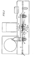
- the general arrangement drawing shown in Figure 2 comprises a welding station for encapsulating the transistors.
- the transistor consists of a base 10 having two flanges lla containing bores llb by which the transistor may be secured in its ultimate assembly.
- the actual semi-conductor component itself is mounted on the base and its electrical connections, comprising two pins 12, project through the base.
- the semi-conductor device is encapsulated by a cap 13, of top hat section, which is circular in plan and which is welded to the base by an electric welding process.
- FIG 2 there is shown a welding station in which the caps 13 are welded to the bases 10 by an electric welding system.
- the transfer of the components through the work station is achieved by apparatus in accordance with the present invention which will be described in greater detail hereinafter.
- the welding process does not form part of the present invention and it will be appreciated that the transport apparatus may be adapted for use in other process steps, being described here only for information.
- the work station includes a closed container 14 within which a "clean" environment is maintained, typically by the use of nitrogen atmosphere.
- the semi-conductor devices on the bases 10 are supplied to the welding station from an oven (not shown) through an airlock 14 and are conveyed, linearly aligned, along a conveyor to a pick and place loading sub-station 16.
- six of the bases 10 are aligned to be loaded into a magazine 17.
- the magazine 17 already has a corresponding number of caps 13 loaded therein by a cap feed assembly 18 where caps are placed into the magazine. The magazine then is placed on top of the bases 10.
- the magazine incorporates a corresponding number of pairs of pins 19 which engage in the securing bores llb in the flanges lla of the bases to thereby accurately locate the bases in the magazine.
- the loaded magazine 17 is then transported on a movable conveyor belt 20 into the welding machine 21.
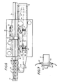
- the magazine In the region of the welding machine 21, the magazine is supported on a fixed surface 22 and is transported through the welding machine 21 by a drive arrangement 23 described in greater detail with reference to Figure 3 and 4.
- the magazine carrying the components which have been welded is transferred onto a further moving conveyor 24 to an unloading station 25 where the completed components are removed from the magazine.
- the empty magazine 17 is then transferred to a transfer conveyor 26 for transfer back to the cap feed assembly 18.
- the welding machine 21 is a conventional electric welding machine having one electrode 27 above the magazine which contacts the cap 13 and a second welding electrode 28 which lies underneath the supporting surface 22 to complete the electrical welding circuit.
- the magazine 17 can be formed of a synthetic plastics material such as TUFNOL which is electrically non-conductive or from copper which then has to move between insulated guides 47.
- the illustrated embodiment is designed to receive six components but can have as many as required. It therefore has six openings 29 linearly spaced and electrically insulated from each other by the main body of the magazine.
- the magazine 17 carries a rack 30 of teeth which are adapted to mate with teeth in an outer surface of a drive conveyor 31.
- the teeth of the rack 30 may be moulded or machined in the plastic body of the magazine 17 or may be, for example, a length of conveyor belt material secured to the magazine 17.
- the magazine On its other side, at least, the magazine carries indicia located accurately to the centre-line of the component position 32 which serve to indicate the presence of a magazine in the apparatus and the position of each opening to a high degree of accuracy, in the magazine. The purposes of the indicia will be described later.
- the drive conveyor 31 consists of a flexible belt having, as described earlier, teeth on its outer surface for driving the magazine and similar teeth on its inner surface for driving engagement with drive sprockets 33 and 34.
- An idler sprocket 35 is located intermediate the main drive sprockets 33 and 34 and serves, in cooperation with the drive sprocket 34 to maintain the belt in alignment with the path of magazines 17 through the machine and in conjunction with the drive sprocket 33 serves to provide a lead-in angle from the said path so that the teeth on the magazine and on the conveyor belt 31 gradually merge. This serves to ensure that the teeth mesh correctly.
- the belt 31 is driven by an electric stepper motor 36 which is connected to a reduction belt drive system 37 which consists of a toothed belt 38 driving a sprocket 39 coaxial with the drive sprocket 34 and rotationally fast thereto. It is possible that the stepper motor 36 may be connected through a reduction gear to the shaft of the drive sprocket 34 to drive the drive sprocket 34 directly but it is preferred that the motor 36 and its related control system is based some way from the welding machine to prevent the inevitable field from the welding current from affecting the operation of the motor or its control gear.
- the belt 31 lies in a path parallel to the path of the magazine 17 through the work station.
- a guide plate 40 is provided slidably mounted in slots 41 transverse to the aforementioned paths so that the position of the face 42 of the plate 40 against which the inner surface of the conveyor belt 31 abuts, can be positioned to ensure that complete engagement is maintained throughout this length of the conveyor between the teeth on the conveyor belt and the teeth on the side of a magazine 17 the magazine being urged against the fixed guide 47.
- the member 40 is clamped in the desired position.
- the control system of the apparatus utilises fibre optics rather than electrical sensors to reduce risk of the control system being affected by the magnetic field of the welding current, whilst also providing higher reliability and improved, consistent performance.
- a magazine When a magazine is transported by the conveyor 20 into the welding station, it is picked up by the conveyor belt 31 at the end of the conveyor 20 and carried by the conveyor belt 31 at a constant speed into the work station.
- a first fibre optic system 43 When the presence of a magazine is detected by a first fibre optic system 43, the speed of the motor and hence the speed of the conveyor belt 31 is reduced from a first, high level, to a low level.
- the high and low motor speeds can be set as required for different magazine sizes, different component feed rates and different component sizes.
- the magazine is then transported slowly until the back edge of the first indicia 32 on the magazine is detected by a further fibre optic detection system 44.
- the fibre optic system 44 is arranged to send a signal to the control system of the motor 36 to stop the motor immediately the indicia 32 is detected.
- the precise position of the fibre optic system 44 is adjustable by a Vernier scale adjuster 45 so that when the motor is stopped the magazine is aligned precisely with the semi-conductor component in the first opening 29 in the magazine 17 so that the component is accurately aligned with the electrodes of the welding apparatus.
- the Vernier scale 45 is usually set when the apparatus is first set up and thereafter no adjustment is usually necessary.
- a further fibre optic system 46 is provided to detect when a magazine leaves the welding station. When this point is detected, and if no further magazines are detected at the first sensing point the speed of the stepper motor 36 is immediately increased to a high level and the magazine is quickly transported to the unloading station referred to earlier.
- stepper motor 36 By providing the accurate drive system incorporating the flexible toothed conveyor belt 31 in conjunction with the stepper motor 36 and reduction gearbox, it is possible to index the movement of the conveyor belt 31 through greater than 2000 steps for each revolution of the stepper motor 36 is required, the precise step at which the motor and hence the magazine is stopped being determined by the associated control system.
- the stepper motor itself may typically provide in the region of 200 steps per revolution and this number can be magnified by at least 10 through the mechanical reduction system and the electronic controller.
- the position of a magazine in the work station can be very accurately determined to ensure that the encapsulated semi-conductor components contained in the magazine are positioned accurately between the electrodes of the welding apparatus to enable a satisfactory weld to be made, whilst at the same time enabling high speed processing of the components to be achieved.
- FIG. 6 illustrates an alternative embodiment in which the driving force for driving the magazine 17 through the work station is generated frictionally.
- the drive conveyor consists of a flexible endless belt 50 having a toothed inner face for positive driving engagement with the drive sprockets 33, 34 and a plane outer surface adapted to frictionally engage the side of a magazine 17.
- the drive conveyor has a lead-in section between the sprockets 33 and 35 and a straight section extending through the work station between sprockets 35 and 34.
- a second flexible endless conveyor 51 extending along the side of the path 20 throughout the work station.
- the conveyor 51 is located by a plurality of idler rollers 52, three being shown, so that the conveyor 51 serves as an abutment for the magazines passing through the work station but since it is able to move freely by virtue of the idler rollers 52 no sliding friction is generated.
- the straight section of conveyor 50 extending through the work station is resiliently biassed towards the the second conveyor.
- a plurality of idler rollers 53 are mounted in an elongate carrier block 54 so as to abut the inner face of the drive conveyor.
- the carrier block 54 is slidable towards and away from the path 20 and is biassed towards the path by springs 55.
- the magazines 17 in this embodiment need not have the toothed rock 30.
- the magazine On entering the work station the magazine is entrained frictionally by the lead-in portion of the drive belt and driven into the work station where it enters between the two conveyor belts 50, 51 for positive driving engagement as it is stepped through the station.
- the resilient force generated by the springs 55 is adjustable to ensure that sufficient frictional forces between the conveyors and the magazines are generated to eliminate slip.
- Deletion of a magazine 17 is made by an optical sensor 56, also shown in Figure 7, the precise position of which can be adjusted by the Vernier scale 45, as previously described.
- the sensor 56 consists of an emitter 57 and a receptor 58 located respectively above and below a magazine in the work station.
- the electronic control system switches the drive to slow speed, if this is required, and indexes the magazine through the station.
- the optical signal or beam from the emitter 57 to the receptor 58 is interrupted by the body of the magazine.
- the magazine has appropriately spaced aligned bore or slots 59 each associated with a respective component so that as a slot is aligned with the sensor a signal is received by the receptor 58 and transmitted to the control system to initiate a welding operation.
- the detection of the end of a magazine is also determined by or transmitted to the control system, by for example the correct number of welds per magazine having been carried out, or by the receptor 58 receiving a signal from the emitter for more than a predetermined length of time.
- the sig'nal from the emitter 57 may pass through grooves 60 milled in the side of the magazine.
- the apparatus of the present invention may be incorporated in any work station where it is desired to quickly and accurately align relatively small components, although it does have particular application to the processing of semi-conductor devices in high speed fully automated processing plants.
- each conveyor will need to have a respective stepper motor to drive it. All of the stepper motors would be controlled by the one electronic controller. This could then automatically stop, start, run at high and low speeds all the conveyors in the system.
Landscapes
- Engineering & Computer Science (AREA)
- Mechanical Engineering (AREA)
- Control Of Conveyors (AREA)
- Feeding Of Workpieces (AREA)
Applications Claiming Priority (2)
| Application Number | Priority Date | Filing Date | Title |
|---|---|---|---|
| GB8425850 | 1984-10-12 | ||
| GB848425850A GB8425850D0 (en) | 1984-10-12 | 1984-10-12 | Feeding components to work station |
Publications (1)
| Publication Number | Publication Date |
|---|---|
| EP0178162A1 true EP0178162A1 (fr) | 1986-04-16 |
Family
ID=10568109
Family Applications (1)
| Application Number | Title | Priority Date | Filing Date |
|---|---|---|---|
| EP85307224A Withdrawn EP0178162A1 (fr) | 1984-10-12 | 1985-10-09 | Appareil pour alimenter une station de travail en composants |
Country Status (3)
| Country | Link |
|---|---|
| EP (1) | EP0178162A1 (fr) |
| JP (1) | JPS61111874A (fr) |
| GB (2) | GB8425850D0 (fr) |
Cited By (5)
| Publication number | Priority date | Publication date | Assignee | Title |
|---|---|---|---|---|
| EP0289194A3 (en) * | 1987-04-27 | 1990-05-16 | American Telephone And Telegraph Company | Method and apparatus for feeding and coating articles in a controlled atmosphere |
| WO1997040656A1 (fr) * | 1996-04-24 | 1997-10-30 | Advanced Systems Automation Limited | Systeme modulaire et coplanaire de mise en forme et d'egalisation |
| CN107855751A (zh) * | 2017-11-22 | 2018-03-30 | 广东金弘达自动化科技股份有限公司 | 一种应用于led灯组装机的上料机构 |
| CN112563374A (zh) * | 2020-12-10 | 2021-03-26 | 许文凡 | 一种太阳能电池生产中硅片检测用自动装片卸片装置 |
| CN116372529A (zh) * | 2023-04-19 | 2023-07-04 | 东莞永昆电机有限公司 | 一种马达减速箱自动装配设备 |
Families Citing this family (1)
| Publication number | Priority date | Publication date | Assignee | Title |
|---|---|---|---|---|
| GB2182625B (en) * | 1985-10-26 | 1989-10-18 | Wilson Foods Corp | Improvements in and relating to conveyors |
Citations (8)
| Publication number | Priority date | Publication date | Assignee | Title |
|---|---|---|---|---|
| DE2164390A1 (de) * | 1970-12-28 | 1972-07-13 | Citizen Watch Co Ltd | Fließbandanlage |
| DE2100881B2 (de) * | 1971-01-09 | 1976-02-05 | Robert Bosch Gmbh, 7000 Stuttgart | Fertigungseinrichtung |
| CH595939A5 (fr) * | 1975-04-15 | 1978-02-28 | Rudi Hutt | |
| US4209898A (en) * | 1977-09-12 | 1980-07-01 | Hitachi, Ltd. | Assembly line for parts of electronic and other equipments |
| FR2498813A1 (fr) * | 1981-01-27 | 1982-07-30 | Instruments Sa | Installation de traitement de materiaux pour la production de semi-conducteurs |
| EP0076231A2 (fr) * | 1981-09-24 | 1983-04-06 | Franz Schäfer | Procédé et appareil pour le traitement et/ou pour l'assemblage en série de pièces à travailler |
| US4417396A (en) * | 1981-11-02 | 1983-11-29 | Elfab Corporation | Method for manufacturing integrated circuit connectors |
| EP0106595A2 (fr) * | 1982-09-28 | 1984-04-25 | Tai-Her Yang | Equipement-outils d'une machine à fonctions multiples |
Family Cites Families (3)
| Publication number | Priority date | Publication date | Assignee | Title |
|---|---|---|---|---|
| GB979185A (en) * | 1962-05-12 | 1965-01-01 | Herbert Ltd A | Improvements in or relating to shuttle tables for transferring a succession of articles |
| US3294037A (en) * | 1963-11-12 | 1966-12-27 | Baker Perkins Inc | Conveyor system |
| US4453807A (en) * | 1981-06-17 | 1984-06-12 | Smithkline Beckman Corp | System for handling slides |
-
1984
- 1984-10-12 GB GB848425850A patent/GB8425850D0/en active Pending
-
1985
- 1985-10-09 EP EP85307224A patent/EP0178162A1/fr not_active Withdrawn
- 1985-10-09 GB GB08524890A patent/GB2165810A/en not_active Withdrawn
- 1985-10-12 JP JP60227622A patent/JPS61111874A/ja active Pending
Patent Citations (8)
| Publication number | Priority date | Publication date | Assignee | Title |
|---|---|---|---|---|
| DE2164390A1 (de) * | 1970-12-28 | 1972-07-13 | Citizen Watch Co Ltd | Fließbandanlage |
| DE2100881B2 (de) * | 1971-01-09 | 1976-02-05 | Robert Bosch Gmbh, 7000 Stuttgart | Fertigungseinrichtung |
| CH595939A5 (fr) * | 1975-04-15 | 1978-02-28 | Rudi Hutt | |
| US4209898A (en) * | 1977-09-12 | 1980-07-01 | Hitachi, Ltd. | Assembly line for parts of electronic and other equipments |
| FR2498813A1 (fr) * | 1981-01-27 | 1982-07-30 | Instruments Sa | Installation de traitement de materiaux pour la production de semi-conducteurs |
| EP0076231A2 (fr) * | 1981-09-24 | 1983-04-06 | Franz Schäfer | Procédé et appareil pour le traitement et/ou pour l'assemblage en série de pièces à travailler |
| US4417396A (en) * | 1981-11-02 | 1983-11-29 | Elfab Corporation | Method for manufacturing integrated circuit connectors |
| EP0106595A2 (fr) * | 1982-09-28 | 1984-04-25 | Tai-Her Yang | Equipement-outils d'une machine à fonctions multiples |
Cited By (7)
| Publication number | Priority date | Publication date | Assignee | Title |
|---|---|---|---|---|
| EP0289194A3 (en) * | 1987-04-27 | 1990-05-16 | American Telephone And Telegraph Company | Method and apparatus for feeding and coating articles in a controlled atmosphere |
| WO1997040656A1 (fr) * | 1996-04-24 | 1997-10-30 | Advanced Systems Automation Limited | Systeme modulaire et coplanaire de mise en forme et d'egalisation |
| CN107855751A (zh) * | 2017-11-22 | 2018-03-30 | 广东金弘达自动化科技股份有限公司 | 一种应用于led灯组装机的上料机构 |
| CN112563374A (zh) * | 2020-12-10 | 2021-03-26 | 许文凡 | 一种太阳能电池生产中硅片检测用自动装片卸片装置 |
| CN112563374B (zh) * | 2020-12-10 | 2022-07-29 | 深圳市赞宇新能源材料科技有限公司 | 一种太阳能电池生产中硅片检测用自动装片卸片装置 |
| CN116372529A (zh) * | 2023-04-19 | 2023-07-04 | 东莞永昆电机有限公司 | 一种马达减速箱自动装配设备 |
| CN116372529B (zh) * | 2023-04-19 | 2023-12-01 | 东莞永昆电机有限公司 | 一种马达减速箱自动装配设备 |
Also Published As
| Publication number | Publication date |
|---|---|
| GB8425850D0 (en) | 1984-11-21 |
| JPS61111874A (ja) | 1986-05-29 |
| GB2165810A (en) | 1986-04-23 |
| GB8524890D0 (en) | 1985-11-13 |
Similar Documents
| Publication | Publication Date | Title |
|---|---|---|
| US6481187B1 (en) | Position sensing system and method for an inspection handling system | |
| US20060103371A1 (en) | Testing system for solar cells | |
| EP0277732A2 (fr) | Moyens de fourniture de composants | |
| KR920006481B1 (ko) | 자동반송장치 | |
| EP0178162A1 (fr) | Appareil pour alimenter une station de travail en composants | |
| CN112284315A (zh) | 检测机 | |
| US4621552A (en) | Method and apparatus for separating printed-circuit boards from multi-board panels | |
| JP2631577B2 (ja) | 搬送装置 | |
| CN216734910U (zh) | 电子元件自动编带机 | |
| EP1516520B1 (fr) | Dispositif servant a transferer des composants electroniques depuis une piste d'alimentation inclinee jusqu'a un autre element | |
| CN211366027U (zh) | 多流道传送装置 | |
| CN114472185B (zh) | 电子元件取放装置及分选机 | |
| TWI833345B (zh) | 取放設備及搬運機台 | |
| CN217005668U (zh) | 一种自动化检测摆盘设备 | |
| EP0278608A2 (fr) | Appareil de préhension par aspiration pour composants électriques ou électroniques | |
| CN112896984B (zh) | 电池上料机构和多电池产品信息追溯方法 | |
| US4412609A (en) | Transport system | |
| CN117401404A (zh) | 料盘自动定位装置 | |
| CN210456392U (zh) | 送检装置 | |
| JPH06186287A (ja) | 電子部品の測定方法及び装置 | |
| US20080047652A1 (en) | Component handling using adhesive-backed carrier tape | |
| JPH07121765B2 (ja) | 自動組立用搬送装置 | |
| CN222956936U (zh) | 药盒检测装置 | |
| JP2523582B2 (ja) | プリント基板搬送方法 | |
| CN224132184U (zh) | 一种定位传输台及元件检测装置 |
Legal Events
| Date | Code | Title | Description |
|---|---|---|---|
| PUAI | Public reference made under article 153(3) epc to a published international application that has entered the european phase |
Free format text: ORIGINAL CODE: 0009012 |
|
| AK | Designated contracting states |
Kind code of ref document: A1 Designated state(s): AT BE CH DE FR GB IT LI NL SE |
|
| STAA | Information on the status of an ep patent application or granted ep patent |
Free format text: STATUS: THE APPLICATION IS DEEMED TO BE WITHDRAWN |
|
| 18D | Application deemed to be withdrawn |
Effective date: 19861017 |
|
| RIN1 | Information on inventor provided before grant (corrected) |
Inventor name: HILL, TERENCE ALBERT |