EP0178265A2 - Läppmaschinen - Google Patents
Läppmaschinen Download PDFInfo
- Publication number
- EP0178265A2 EP0178265A2 EP85830077A EP85830077A EP0178265A2 EP 0178265 A2 EP0178265 A2 EP 0178265A2 EP 85830077 A EP85830077 A EP 85830077A EP 85830077 A EP85830077 A EP 85830077A EP 0178265 A2 EP0178265 A2 EP 0178265A2
- Authority
- EP
- European Patent Office
- Prior art keywords
- workpiece
- plate
- shaft
- lapping
- engaging
- Prior art date
- Legal status (The legal status is an assumption and is not a legal conclusion. Google has not performed a legal analysis and makes no representation as to the accuracy of the status listed.)
- Withdrawn
Links
- 238000000034 method Methods 0.000 claims description 4
- 239000003082 abrasive agent Substances 0.000 claims 1
- 239000006194 liquid suspension Substances 0.000 claims 1
- 239000002184 metal Substances 0.000 claims 1
- 230000002093 peripheral effect Effects 0.000 description 4
- 230000004048 modification Effects 0.000 description 2
- 238000012986 modification Methods 0.000 description 2
- 238000007689 inspection Methods 0.000 description 1
- 230000013011 mating Effects 0.000 description 1
- 238000007790 scraping Methods 0.000 description 1
- 238000009827 uniform distribution Methods 0.000 description 1
Images


Classifications
-
- B—PERFORMING OPERATIONS; TRANSPORTING
- B24—GRINDING; POLISHING
- B24B—MACHINES, DEVICES, OR PROCESSES FOR GRINDING OR POLISHING; DRESSING OR CONDITIONING OF ABRADING SURFACES; FEEDING OF GRINDING, POLISHING, OR LAPPING AGENTS
- B24B37/00—Lapping machines or devices; Accessories
- B24B37/04—Lapping machines or devices; Accessories designed for working plane surfaces
- B24B37/042—Lapping machines or devices; Accessories designed for working plane surfaces operating processes therefor
Definitions
- the present invention relates to improvements in lapping machines each provided with a horizontal and circular lapping plate which will be referred to as "circular plate”.
- the workpieces are kept apart from one another within said ring by a flat jig vertically slidable along the wall of said ring, said jig being provided with through holes adapted for mating the periphery of the workpieces.
- a single pressing load is placed on top of all the workpieces within said ring which load is proportioned to the total area of all the workpieces contacting the plate.
- the main drawback of the lapping machine according to the above mentioned pior art consists of the fact that each of the pieces to be lapped is driven to constantly slide along the same circumferential path and as result the plate surface is worn along concentric circumferences.
- Another drawback originates from the fact that a single load is collectively applied on all the workpieces within the same ring which load could not be uniformly distributed due to slight differences of the piece heights.
- the present invention is aimed to eliminate the above drawbacks.
- each workpiece is moved over the lapping plate alternately towardds the rotation axis of the plate and away therefrom.
- the path length the workpiece for each revolution of the plate is the same for all the workpieces and not longer for the pieces which are farther from the plate axis as it occurs in the lapping machines of the cited prior art.
- each workpiece in addition to being drawn over the plate is also rotated about its own vertical axis which passes through the center of figure of its surface in contact with the plate.
- the force by which each workpiece is pressed on the plate can be adjusted to a value different from the other pieces.
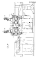
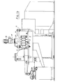
- the lapping machine of this invention comprises a mounting structure 3 having a horizontal table 5 provided with an ample circular aperture from which the lapping plate 9 emerges which has a circular shape with the lapping surface upwards.
- Plate 5 is rotated by a geared motor enclosed in the machine mounting structure 3 and not shown.
- the lapping surface of plate 9 as in the above patent is provided with grooves 10 in a ray pattern for the uniform distribution of the abrasive mix.
- Three columns 11 are affixed onto mounting structure 3 which extend upwards to sustain a support plate 13 on which two identical electric motors with vertical axes are mounted which are provided with variable-speed gears 17.
- Motors 15 drive each an identical mechanical assembly of which only one will therefore be described.
- a shaft 19 extends from each variable-speed gear 17 into a casing 21 and terminates with a pinion 23.
- Casing 21 rests on plate 13 being coupled thereto by means of key 25 which prevents any rotation of the casing with respect to mounting structure 3.
- Casing 21 is partially protected by a cover 27 which can be opened by rotating it about a pin 29 for inspection of the casing inside.
- a stiff stationary structure 31 is firmly attached to plate 13, a cylindrical cavity 31' being provided at the structure center into which the shaft 32 of a rotary disk or rotor 35 extends which rotor is supported within stationary structure 31. by means of two roller bearings 37 and 39.
- Output pinion 23 from variable-speed gear 17 engages a first gear wheel 41 on whose axis a pinion 43 is mounted which engages a second gear wheel 45.
- the shaft 47 of the latter extends downwards through plate 13 and stationary structure 31 and thereafter terminates with a pinion 49 which engages the internal toothing of which rotor 35 is provided.
- Rotor 35 at its periphery carries a circular row of workpiece-holders 51 (see Figs. 2, 4a and 4b) which function for getting hold of the workpieces and driving them along the surface of the lapping plate 9 and at the same time for imparting a rotary movement to each of them about its own vertical axis.
- Piece-holder 51 (figs.4a and 4b) comprises a bracket 73 which is attached by means of a dovetail joint 35' to rotor 35 at the periphery thereof.
- Bracket 73 is provided with a vertical through bore into which a hollow cylinder or barrel 53 is slidably but not rotatably fitted.
- a shaft 55 In the central bore of barrel 53 a shaft 55 is rotatably supported by three ball bearings of which two, 57 and 59 at either end of shaft 55, are journal bearings and one, 61 at the lower end of the same shaft is a thrust bearing.
- shaft 55 for about 1/3 of its length is provided with a straight toothing for engaging a toothed ring 65 which is fixedly mounted by means of a row of screws 67 on a peripheral flange 69 of stationary structure 31.
- Shaft 55 whose toothing engages the toothing of ring 65, is thus driven to rotate about its axis when rotor 35 and consequently the piece-holders are rotating.
- Shaft 55 at its lower end carries an adapter 71 for catching the workpiece to be lapped by means of suitable teeth engageable therewith; such adapter being consequently replaceable to fit different workpiece heads.
- a slope 79 is included in race 77 on which bearing 75, while traveling in the direction of arrow F of Fig.3a, rises on top of an elevated section 84 of race 77 which section extends through an arc of about 30° which corresponds about to the distance from the delivery point 81 of the final workpiece to the inlet point of a fresh workpiece to be lapped.
- the shaft 55 is also lifted and adapter 71 abandons the finished workpiece and subsequently engages the fresh workpiece when bearing 75 drops from the cam.
- a trapezoidal block 85 is mounted at the upper end of arm 53 which block has a horizontal lower base and a slant upper base with a 20 deg inclination to the horizontal, the side faces of the block being flat and vertical. One of the side faces is provided with a recess for receiving ball bearing 75 therein; both the latter bearing and block 85 being fastened to arm 53' by a single Allen screw 87.
- the upper slant base of block 85 is intended for engaging a roller 86 (Fig.2) which is biassed downwards by an adjustable helical spring which is housed in a hollow cylinder fixedly attached to stationary structure 31.
- the purpose of the mechanism comprised of block 85, roller 86 and spring 89 is for applying an adjustable thrust on barrel 53 and consequently on adapter 71 against the workpiece at the moment when they meet and securely engaging each other for starting the circular movement over the lapping plate.
- a second helical spring 91 is received in a cylindrical casing 73' for accurately adjusting the pressure to be applied on each workpiece during its travel over the lapping plate said casing being fastened to bracket 73 included in holder assembly 51 and then rotatable with rotor 35.
- Spring 91 which is biassed by a threaded plug 92 exerts, through a vertical cylinder 93 and a horizontal pin slidable along a vertical slit 99 of which the wall of casing 73' is provided, a downward force on barrel 53 and consequently on shaft 55 and on adapter 71 engaged with the workpiece.
- the workpiece holders are driven to follow a circular path over the lapping plate and the paths of the two groups of holders are symmetrical with respect to a diametrical symmetry plane of plate 9 and each of them occupies only a quarter of the plate surface.
- the other half of the plate over which the holders do not travel is used for reconditioning that is for grinding the lapping surface of plate 9.
- a ring 101 is disposed on the free half of the plate which ring is amply discussed in Patent 1.003.959, the position of said ring on the plate being controlled by an arcuate arm 103 already described in Italian Patent 751.572.
- the paths of the workpieces over the lapping plate can be other than circular: for instance they may be elliptical, hypocycloidal etc. provided that the workpiece path leads it from peripheral points to central points of the lapping plate or from peripheral points to peripheral points but passing over the central area of the plate. It should therefore be understood that all the modification and variants which are made within the true spirit of the invention are protect by the following claims.
Landscapes
- Engineering & Computer Science (AREA)
- Mechanical Engineering (AREA)
- Finish Polishing, Edge Sharpening, And Grinding By Specific Grinding Devices (AREA)
Applications Claiming Priority (2)
| Application Number | Priority Date | Filing Date | Title |
|---|---|---|---|
| IT4896984 | 1984-10-05 | ||
| IT48969/84A IT1178038B (it) | 1984-10-05 | 1984-10-05 | Perfezionamento alle macchine lappatrici |
Publications (1)
| Publication Number | Publication Date |
|---|---|
| EP0178265A2 true EP0178265A2 (de) | 1986-04-16 |
Family
ID=11269222
Family Applications (1)
| Application Number | Title | Priority Date | Filing Date |
|---|---|---|---|
| EP85830077A Withdrawn EP0178265A2 (de) | 1984-10-05 | 1985-03-29 | Läppmaschinen |
Country Status (2)
| Country | Link |
|---|---|
| EP (1) | EP0178265A2 (de) |
| IT (1) | IT1178038B (de) |
Families Citing this family (1)
| Publication number | Priority date | Publication date | Assignee | Title |
|---|---|---|---|---|
| CN113664715B (zh) * | 2021-08-30 | 2024-09-27 | 兰州兰石能源装备工程研究院有限公司 | 磁性研磨机生产线驱动进给装置 |
-
1984
- 1984-10-05 IT IT48969/84A patent/IT1178038B/it active
-
1985
- 1985-03-29 EP EP85830077A patent/EP0178265A2/de not_active Withdrawn
Also Published As
| Publication number | Publication date |
|---|---|
| IT8448969A1 (it) | 1986-04-05 |
| IT1178038B (it) | 1987-09-03 |
| IT8448969A0 (it) | 1984-10-05 |
Similar Documents
| Publication | Publication Date | Title |
|---|---|---|
| EP0178843A2 (de) | Flachschleifmaschine | |
| EP0046604B1 (de) | Werkzeug zum Schruppen, Glätten und Polieren fester Oberflächen, insbesondere geeignet für steinige Materialien | |
| US4062150A (en) | Centerless grinding method and device using same | |
| US4222203A (en) | Machining device and method | |
| EP0626235A2 (de) | Spitzenlose Schleifmaschine und Abrichtvorrichtung für Schleifscheibe | |
| GB2186823A (en) | Double-end surface grinding machine | |
| US4015370A (en) | Machine for grinding of peripheral surfaces on work pieces | |
| EP0178265A2 (de) | Läppmaschinen | |
| US3866359A (en) | Surface grinding apparatus | |
| JP3835255B2 (ja) | ギア歯面加工方法及び装置 | |
| US3710514A (en) | Apparatus for superfinishing of rotary crankpins of crankshafts | |
| JP5213553B2 (ja) | 研削装置および研削方法 | |
| EP0316381B1 (de) | Läpp-maschine, insbesondere für feine oberfläche bearbeitung von lager-kugeln | |
| SU1116976A3 (ru) | Станок дл шлифовани торцевых поверхностей деталей | |
| KR100434182B1 (ko) | 엔드밀을 이용한 원통체의 내외면 홈 가공방법 및 장치 | |
| US971861A (en) | Grinding-machine. | |
| JP3192963B2 (ja) | 研磨装置 | |
| JP2610930B2 (ja) | 研削装置 | |
| US4891914A (en) | Computer controlled universal grinder and method for grinding trochoidal and circular bearing races | |
| GB2151955A (en) | Grinding machines | |
| CN223519403U (zh) | 一种陶瓷棒双面研磨治具 | |
| SU1364447A2 (ru) | Станок дл доводки наружных цилиндрических поверхностей деталей | |
| EP0336312A2 (de) | Computergesteuerte universale Schleifmaschine und Verfahren zum Schleifen von hypo-, epitrochoidischen und kreisförmigen Laufbahnen | |
| JPH0818248B2 (ja) | ジヤイロ研磨方法および機械 | |
| JPH1110536A (ja) | ツルーイング装置及び方法 |
Legal Events
| Date | Code | Title | Description |
|---|---|---|---|
| PUAI | Public reference made under article 153(3) epc to a published international application that has entered the european phase |
Free format text: ORIGINAL CODE: 0009012 |
|
| AK | Designated contracting states |
Kind code of ref document: A2 Designated state(s): CH DE FR GB LI |
|
| STAA | Information on the status of an ep patent application or granted ep patent |
Free format text: STATUS: THE APPLICATION IS DEEMED TO BE WITHDRAWN |
|
| 18D | Application deemed to be withdrawn |
Effective date: 19870401 |
|
| RIN1 | Information on inventor provided before grant (corrected) |
Inventor name: MELCHIORRE, MICHELE |