EP0178370A2 - Machine pour le traitement automatique de surfaces - Google Patents
Machine pour le traitement automatique de surfaces Download PDFInfo
- Publication number
- EP0178370A2 EP0178370A2 EP85102329A EP85102329A EP0178370A2 EP 0178370 A2 EP0178370 A2 EP 0178370A2 EP 85102329 A EP85102329 A EP 85102329A EP 85102329 A EP85102329 A EP 85102329A EP 0178370 A2 EP0178370 A2 EP 0178370A2
- Authority
- EP
- European Patent Office
- Prior art keywords
- dressing
- roller
- rollers
- conveyor
- fillet
- Prior art date
- Legal status (The legal status is an assumption and is not a legal conclusion. Google has not performed a legal analysis and makes no representation as to the accuracy of the status listed.)
- Withdrawn
Links
Images


Classifications
-
- A—HUMAN NECESSITIES
- A22—BUTCHERING; MEAT TREATMENT; PROCESSING POULTRY OR FISH
- A22C—PROCESSING MEAT, POULTRY, OR FISH
- A22C25/00—Processing fish ; Curing of fish; Stunning of fish by electric current; Investigating fish by optical means
- A22C25/17—Skinning fish
Definitions
- This invention relates to surface dressing apparatus, and more particularly to a unique apparatus for automatically removing a surface layer from objects of varying size and curvilinear contour.
- Price proposes a power-driven abrading roller for removing scales of a fish held in the operator's hands with the aid of tongs.
- Baader proposes a rotating loading table for transferring fish onto a second table operable to pass fish past slitting, trimming, and dressing devices primarily restricted to removing the opposite ends of a fish and its entrails.
- Schlichting is also concerned with the provision of a machine for passing fish past cutting knives each designed for performing a different operation.
- Evich 2,915,759 proposes two machines, one of which is designed to cut the throat of a fish conveyed past a rotating knife and the second performing a slitting operation lengthwise of the fish belly.
- Henderson discloses a fish dressing apparatus for passing predressed and quartered tuna past two independent processing stations each equipped with photoelectric controlled dressing knives, operable to remove dark meat characteristic of the tuna species.
- the apparatus requires manual inversion of the fish before processing by the second processing station.
- the two latest Evich patents propose apparatus for advancing fish fillets past several groups of power-driven scale-removing dressing rollers.
- the rollers are mounted transversely of the ends of arms restricted to pivotal movement in different radial planes extending lengthwise of the advancing fillets.
- These arms are equipped with sensor means controlling a pneumatic actuator for adjusting the dressing roller in a radial plane relative to the fillet.
- the last issued Evich patent proposes a more sophisticated servo adjusting mechanism for the dressing rollers.
- the wide dressing rollers are mounted on arms arranged in an arc about the fillet conveyor and pivot in radial planes as well as about the axes of their respective supporting arms rather than about an axis tangent to the area of the rollers in dressing contact with the fillet as is crucially important to efficient and non-wasteful dressing.
- Each arm is provided with a complex pneumatic-hydraulic actuator operable to shift the arms in the radial planes in response to a fillet- engaging, rockable sensor embracing and pivoting about the axis. the dressing rollers.
- the multiplicity of dressing of rollers, each controlled by independently operable complex servo control systems of the type just mentioned involve difficult and costly maintenance and operating problems and has been found inadequate to avoid the removal of excess fillet flesh.
- the present invention is the culmination of more than twenty five years of effort to overcome the serious problems attending attempts to dress a layer of predetermined thickness from an object, such as fish, having texture, flexibility, pliancy and flabbiness and varying in size and shape.
- Automatic apparatus for accomplishing these objectives in a most efficient, non-wasteful and satisfactory manner is provided by this invention.
- the fish fillets or other objects to be dressed are conveyed past a dressing station equipped with a multiplicity of relatively narrow, small diameter dressing rollers and distributed along the path of advance and each arranged to dress a separate strip of uniform thickness from the fillets whereby the entire surface has been dressed away when the fillet has passed the last roller.
- Each dressing roller is biased into predetermined pressure contact with the fillet.
- the depth of the dressed layer is controlled by shoe means positioned closely beside the roller ends and operable to pivot the roller about an taxis tangent to the rollers' line of contact with the fillet.
- This novel expedient avoids the removal of excess material and insures that a layer of uniform thickness will be removed.
- the pressing rollers are mounted on individual supporting arms counterweighted to pivot away from the fillet in its own vertical Plane extending lengthwise of the conveyor.
- a separate manually adjustable counterweight is provided to pivot each roller supporting arm to a preselected neutral position to a position wherein the plane of the associated dressing roller lies normal to an area being dressed.
- auxiliaries include suction air and fluid noistened means associated with each dressing roller to convey cuttings away therefrom and one or more auxiliaries upstream from the dressing station to prepare the fillet surface for more efficient removal by the dressing rollers and to loosen, if not remove fins and bony structures associated with the fins as the fillets approach the dressing station.
- Another object of the invention is the provision of improved method and apparatus for automatically processing fish fillets to remove fins and a layer of predetermined thickness therefrom.
- Another object of the invention is the provision of a novel power-driven, floatingly supported dressing roller having separate, manually adjustable means for biasing the roller into uniform contact with an object to be dressed thereby to remove a layer of predetermined thickness therefrom.
- Another object of the invention is the provision of automatic surface-dressing apparatus having conveyor means for advancing an object to be dressed past a dressing station equipped with groups of floatingly supported dressing rollers and spaced apart lengthwise of the dressing station, each group including independent, power driven dressing rollers, each positioned to dress a different strip of predetermined, uniform thickness controlled by a surface-contracting shoe located to either side of each dressing roller.
- Another object of the invention is the provision of automatic apparatus for dressing fish fillets of differing size and contour, utilizing a multiplicity of dressing rollers each independently supported by individually adjustable counterweight means operable to bias each dressing roller in a direction to dress a strip of uniform thickness from an object of varying curvilinear contour undergoing dressing.
- Another object of the invention is the provision of a method and apparatus for dressing a surface layer of predetermined thickness from a fish fillet and removing the fluid moistened cuttings in a suction air stream.
- Another object of the invention is the provision of an apparatus and method for dressing the scales, fins and skins from fish fillets, utilizing surface loosening and grooving auxiliaries upstream from power-driven surface dressing means.
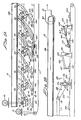
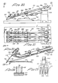
- FIG. 1A and 1B Apparatus for practising the principles of this invention arranged with auxiliaries suitable for dressing the skin, scales and fins from fish fillet, designated generally 10, is illustrated in Figures 1A and 1B.
- the apparatus has a conveyor 1 driven by a variable speed motor 12 and a belt 13.
- the pparatus includes a suitable main frame, not shown, but nderstood as providing a support for all components, including set speed motor 14 having a main drive belt 15 connected to a ulley 16 supplying power to a plurality of belts 17 and a plurality of pulleys 18 connected in series lengthwise of conveyor 11.
- the pulleys 18 are mounted on shafts 19 extending rosswise of conveyor 11.
- each of the shafts 9 is provided with a pair of pulleys supporting a pair of belts 7.
- Shafts 19 also support separate drive pulleys 18 for a rive belt 45 for the floatingly supported surface dressing mechanisms designated generally 20 in Figure 1A.
- the details of echanisms 20 are shown in Figures 2 to 5 and elsewhere.
- the drive belt 17 shown at the righthand end of Figure 1A and at he lefthand end of Figure 1B is connected by a belt 22 to a dressing accessory designated generally 26.
- Figure 1B are two additional belt-driven ressing accessories, including a surface loosening and cratching accessory 25 and a surface grooving and scraping accessory 23, each mounted on brackets straddling the conveyor attached to the main frame.
- Manifold 28 opens into the inlet of a power-driven suction fan 30 having an outlet 31 discharging the material dressed from the fish or other object to a point of disposal.
- Manifold 28 is connected by separate lengths of flexible tubing 33 to the rear ends of each dressing mechanism 20 each of which is provided with a tubular duct, to be described presently, opening into a shroud embracing the surface dressing roller of the dressing mechanisms 20. Accordingly, all scales, skin and other cuttings removed by the dressing rollers are carried away in the strong, suction air stream flowing in the suction manifold 28.
- Fluid moistening of the cuttings flowing through the dressing mechanisms 20 provided by a spray of fluid introduced from a pressurized fluid supply pipe 29 is found to expedite the flow of the cuttings and to avoid adherence of these to parts of the suction passage.
- the multiplicity of floating dressing mechanisms 20 are distributed crosswise and lengthwise of the forward end of the conveyor 11 shown in Figure 1A.
- the structural and operating details of these mechanisms are shown in Figures 2 through 13 and 25 to 27, wherein there are a total of twenty independently mounted and driven -mechanisms, each having its own dressing roller, independently adjustable counterweight and biasing components and its own flexible suction hose connection 33 discharging into the suction maniford 28.
- Mechanisms 20 are arranged in five groups of three mechanisms and at least one group of five mechanisms, with the dressing rollers and their supporting arms being supported on a horizontal axis extending transversely of the conveyor.
- the single dressing roller supported by each mechanism 20 dresses a relatively narrow strip from the object being dressed, such as a fish fillet, it being understood that the combined width of the eighteen dressing rollers represents the maximum width of a fillet dressable by apparatus 10. Most fillets will of course be of substantially less width than the maximum size, in which event the dressing rollers positioned laterally outside the fillet will be inactive and with the dressing roller positioned in a rest position closely spaced to the conveyor surface as shown by way of example at the foremost end of Figure 1A.
- Each dressing mechanism is positioned to remove only a designated narrow strip of the whole width of the fillet.
- Most of the dressing mechanisms are restricted to a pivotal movement in a vertical plane longitudinally of the conveyor, whereas the dressing roller itself is free to pivot in a limited arc about an axis tangent to the rollers' line of contact with the object being dressed.
- all rollers including the outermost one can pivot to dress a strip of uniform thickness from the contiguous area of the fillet including the lateral edge of a fillet lying at an obtuse angle to the conveyor. This is true even though all except the outermost dressing mechanisms as a whole are restricted to pivot in a vertical plane.
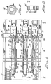
- FIGS 2, 3 and 4 show three dressing mechanisms 20 supported on a shelf 35 extending horizontally crosswise of the conveyor with its ends anchored to the main frame by upright brackets 36.
- the main body of each dressing mechanism has a long tubular, arm 37, the righthand or rear end of which is embraced by a pair of anti-friction bearings 38 ( Figure 5) mounted in a housing 39.
- Projecting forwardly from the front end wall of housing 39 are a pair of lugs 40, 40 provided with aligned openings journalled on the inner ends of shouldered screws 41 ( Figure 3) mounted in the legs of a U-shaped bracket 42 rigidly clamped to shelf 35 by a nut and bolt 43.
- One of the pivot screws 41 for each of the dressing mechanisms is longer than the other and supports a pulley 44 having a pair of grooves, one of which supports a belt 45 driven by an associated one of the pulleys 18 of the main power supply shown in Figure 1A.
- the other groove of each of the pulleys 44 seats a belt 47 extending along the side of each of the dressing mechanisms 20 and driving a pulley 48 integral with a respective dressing roller 50 of that mechanism, as clearly appears from Figure 10.
- the major portion of dressing rollers 50 is enclosed within a hollow shroud 53 telescoped over the forward end of arm 37.. These rollers are supported on non-corrosive anti-friction bearings 54, such as nylon balls 55.
- each pipe is preferably equipped with spray ports 32a and 32b. Both of these ports are located in the sidewall of the pipe, port 32a being adjacent the forward end of the pipe and disposed to spray fluid into opening 83 of shroud 53 ( Figures 4-6) and opening 32b being disposed to spray fluid onto the rotary fittings at the forward end of housing 39 for the tubular arm 37 ( Figure 5).
- Adjacent portions of arm 37 includes ports, now shown, permitting small quantities of the spray and air to enter arm 37 and aid in preventing the deposit of cuttings in these areas.
- 'Pipe 29 may be formed of stainless steel and is suitably supported in brackets 31 and positioned for the most effective delivery of the spray into the air entering opening 83, onto dressing roller 50 and into the contiguous interior areas of shroud 53 to flush away and prevent the deposit of cuttings.
- Port 32b functions similarly to avoid the collection of cuttings in the area adjacent the rear portion of tubular arm 37.
- shoe 65 The depth of the dressing cut made by dressing rollers 50 is controlled by a shoe, designated generally 65, underlying the shroud 53 and best shown in Figures 2, 5 and 9. As there I shown, shoe 65 is pivotally supported by a pivot pin 66 ( Figure 7). Shoe 65 has a long, generally rectangular opening 68 '( Figure 9) sufficiently wide as to closely embrace the opposite sides of the dressing roller 50. The lower, semi-cylindrical surfaces 70 are spaced radially inwardly of the periphery of the dressing rollers by the thickness of the layer to be dressed from the fillet or other object undergoing dressing.
- This layer is controlled by adjusting a thumb nut 73 having its shank threaded into the forward end of shoe 65, the upper end of this shank being loosely accommodated in a notch 74 ( Figure 7) in shroud 53.
- a compression spring 75 surrounding the shank of the thumb nut 73 urges the shoe to pivot counterclockwise about its pivot pin 66 as is evident from Figure 7. It will be understood that tightening the screw 73 increases the thickness of the cut made by the dressing roller, whereas loosening it diminishes the thickness of the cut.
- an adjustable plate 78 for restricting the flow of suction air into the underside of shroud 53 and having a slot 79 at its rear end to accommodate a thumb nut 80 mounted in a threaded bore on the underside of shroud 53. Loosening of this thumb nut enables the operator to adjust the plate 78, relative to the periphery of the dressing roller 50 so as to constrict or regulate the suction air stream entering the tubular arm 37 most effectively to entrain cuttings produced by the dressing roller.
- Another major portion of the suction air stream enters shroud 53 through an opening 83 ( Figure 7) located along the side walls of shroud 53.
- opening 83 is located only in the side wall closest to pulley 48, the other side wall being closed and provided with a mounting slot 61 accommodating the shaft of the dressing roller and permitting the roller to be quickly detached when nut 62 is loosened.
- each mechanism 20 is provided with a sensing shoe 81 in the form of a long resilient blade underlying the associated tubular arm 37.
- Shoe 81 is adjustably supported on arm 37 by set screws and brackets 82.
- the forward end of sensing shoe 81 has gently upwardly curved lateral edges.
- mechanism 20 and sensing shoe 81 occupy an inactive rest position close to the conveyor as is shown in Figure 2.
- Further forward movement brings the forward end of the fillet into contact with sensor 81 thereby pivoting the dressing mechanism clockwise sufficiently to position the dressing roller 50 or 50' at the appropriate elevation and properly oriented about the pivot axis 99 ( Figure 5) to lie in a plane normal to the underlying fillet surface.
- shoe 81 remains in light pressure contact with the fillet and effective to pivot the dressing mechanism about axis 99 if necessary to maintain roller 50 normal to any change in the contour of the fillet.
- spring 89 pivots the dressing mechanisms 20 to a rest position with the dressing roller just clear of conveyor 11 as shown in Figure 2.
- This rest position is determined by a thumb screw 94 ( Figure 5) seated in a threaded bore of housing 39 and having its forward end passing loosely through a bifurcated bracket 96 secured to bracket 42.
- the sector-shaped counterweight 86 in the rear end of housing 39 tends to pivot the tubular arm 37 and' the dressing roller about the axis of bearings 38 to a desired preselected neutral positioned determined by the adjusted position of the counterweight circumferentially of tube 37.
- the lefthand roller 50 lies in a plane normal to the underlying surface of the fillet and inclined to the left from a vertical plane
- the righthand-most dressing roller 50 lies in a plane likewise normal to the underlying surface of the fillet but inclined in the opposite direction from a vertical plane
- the center dressing roller 50' lies substantially in a vertical plane since the underlying area of the fillet is substantially horizontal.
- adjustment of the counterweight 86 can be accomplished by removing cap 88, loosening the set screw 87 and shifting the second-shaped counterweight 86 about the axis of the rear end of this tube to a position effective to rotate tube 37 and the associate dressing roller to a desired null position with the roller lying normal to the area of a fillet to be dressed thereby.
- the surface dressing apparatus of this invention preferably includes at least one pair of dressing mechanisms disposed on to either lateral side of the fillet or other object being dressed and differing from dressing mechanisms 20 only in minor respects which will now be described by reference to Figures 1A and 25 through 27.
- Mechanisms 20' are pivotally supported on the main frame for the dressing apparatus along either lateral side of the path of travel of the fillets and pivot generally about a vertical axis rather than about a horizontal axis as do the dressing mechanisms 20 described above.
- the bearing housing 39 at the rear end of mechanisms 20 and 20' includes a mounting ring 98' having brackets 40' extending forwardly from diametrically opposed sides as is clearly shown in Figure 25.
- brackets 40' supports pulleys for drive belts 45', 47 and the other bracket 40' is welded to a shaft 130 which is journalled in a pillow block 131 anchored to the main frame of the apparatus by cap screws 132.
- a pair of arms 134 and 135 are welded to the opposite ends of shaft 130.
- Arm 134 extends generally lengthwise along the side of the apparatus main frame and is provided with an adjustable stop screw 136 at its outer end which bears against the 'main frame to limit the clockwise movement of dressing mechanism 20' toward the fillet.
- the other arm 135 projects outwardly away from the sidewall of the frame and supports an adjustable tension spring 89' having its lefthand end as viewed in Figure 27 anchored to the apparatus frame and adjustable to vary the pressure of the dressing roller 50 (Figure 26) against the fillet.
- housing 39 encloses an adjustable counterweight 86 adjusted to a position biasing the dressing roller 50 to a neutral position against the generally vertical side of a fillet.
- the fin remover auxiliary 26 has the features displayed in Figures 18 and 19; the surface loosening auxiliary 25 having the structural features illustrated in Figures 13 through 17; and the surface grooving auxiliary 26 having the features illustrated in Figures 20 through 24.
- the rear end of conveyor 11 is preferably but not necessarily equipped with each of the auxiliaries 23, 25 and 26, but some or all of these auxiliaries may be dispensed with at the user's option when dressing other objects or even when dressing certain species of fish.
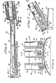
- this auxiliary includes a multiplicity of elongated circular rods 102, 102 the rear ends of which pass loosely through bores in trunions 103 each having a pair of aligned trunion pins pivotally supported in brackets 104 mounted in an upright position in an inverted U-shaped bracket 105 secured to the main frame of apparatus 10.
- Rods 102 are free to rotate about their own axis in trunions 103 and are held loosely assembled thereto by a pair of collars 106.
- bracket 105 underlies rods 102 and acts as a stop to limit the downward pivotal movement to a rest position in which the foremost end of each auxiliary 23 is located slightly above the conveyor 11 as indicated in Figure 20.
- rods 102 are slidably journalled in a tube 160 (Figure 20) connected to bracket 105 by an adjustable linkage including a turnbuckle 161.
- One end of this turnbuckle is pivoted to a lug fixed to bracket 105 and the other end is pivoted to a sleeve 162 embracing tube 160 and restrained from movement therealong by set screw equipped collars 163.
- a tubular bearing 110 (Figure 22) loosely and pivotally supporting the shank 111 in which is rigidly secured a surface grooving device 112 formed of strip spring steel or the like.
- Device 112 has a plurality of sharp-edged and pointed grooving fingers 115 each spaced to either side of resilient strip spring scraping blades 116. The operating relationship between the sharp cutting tips of the blades 115 and scrapers 116 is best shown in Figures 22 and 24.
- the sharp points of the grooving blades 115 are effective to form grooves in the skin 117 of a fillet 100, whereas the straight transverse free ends of scrapers 116 bear firmly against the skin between adjacent grooves and are effective to loosen if not remove some or all of the skin as the fillet advances therepast.
- the grooving device is elevated from its normal position of rest shown in Figure 20 into a proper operating position by a resilient shoe 120 secured to the forward end of arms 102 by clamps 121.
- shoe 120 is in contact with the foremost end of a fillet 100 in Figure 22 with the result that fingers 115 and blades 116 are in approximate position to groove the skin 117 of the fillet as it advances a short distance forward of the position shown.
- each of the arms 102 can include counterweights or spring means for pivoting them clockwise about their respective trunion axes to render them more effective in grooving and scraping the fillet skin. Additionally, it will be understood that the tubular portions of arms t02 are free to pivot about their longitudinal axes so that each of the skin grooving elements 115 and scrapers 116 will be equally effective on the underlying surface of the fillet advancing therepast.
- Figures 18 and 19 show details of the fin loosening auxiliary designated generally 26 supported crosswise of a conveyor 11 on an inverted U-shaped bracket 123. Journalled in the legs of this bracket is a shaft 125 driven counterclockwise by a belt 22 and motor 14 ( Figure 1A). Clamped to shaft 25 are a plurality of resilient fingers 127 having transversely serrated outer ends 128. These fingers are highly effective in detaching the remaining portions of loose skin and or fins and bony parts protruding from the fillets. When the apparatus is not used to dress fillet, auxiliary 26 may be detached or deactivated.
- FIGs 13 through 17 show details of the surface loosening auxiliary 25 mounted transversely of the rear end of conveyor 11 between auxiliaries 23 and 26 as is best shown in Figure 1B.
- Upright brackets 130 have their lower ends pivotally secured to the apparatus' main frame by pivot cap screws 131.
- the thumb nut 132 on the outer end of a threaded stud secured to the main frame and extending through slot 133 of brackets 130 ( Figure 13) permit brackets 130 to be adjusted through short forward or rearward arcs about cap screws 131.
- the rear ends of a plurality of arms 135 are pivotally supported on a shaft 136 mounted between the upper ends of brackets 130.
- a second shaft 138 underlies each of the arms forwardly of shaft 136 and acts as a stop to limit counterclockwise pivotal movement of the arms 135 about shaft 136.
- a lug 140 Secured to the side of each of arms 135 is a lug 140 having a threaded bore supporting an adjustable cap screw 142 positioned to bear against the underlying shaft 138.
- the adjustable stop provided by cap screw 142 limits the downward pivotal movements of the arms 135 to a position just clear of conveyor 11, when no object is undergoing dressing it is positioned beneath the forward ends of the arms 135.
- a surface loosening device designated generally 144
- a resilient spring blade 145 having its upper end extending into a slotted support 146 and held adjustably lengthwise of this slot by a clamp 147.
- Welded onto one face of spring 145 is a lug 149 rotatably supporting the shank 150 ( Figure 15).
- a wide resilient spring strip Secured to the lower end of shank 150 is a wide resilient spring strip as shown in Figure 15.
- the lower end of spring 145 extends below and is curved forwardly to a position closely spaced behind the fillet scraping spring 152.
- spring 152 Since spring 152 is normally spaced from the lower end of spring 145, it is free to rotate in a limited arc about the axis of shank 150 before engaging one or the other lower corner of spring 145.
- Spring 152 may comprise a single spring but preferably is quite wide transversely of the conveyor and its lower portion is provided with a plurality of vertical slits 154 dividing strip member 152 into a plurality of independently flexible fingers 155 ( Figure 16). The lower fillet contacting ends of these fingers may be bevelled as is indicated at 156, a feature found effective in loosening and removing skin from the fillet.
- the apparatus is powered by the motor 12 driving conveyor 11 and by motor 14 driving a multitude of surface dressing mechanisms 20 and a separate motor driving the suction blower 30 functioning to remove skin and cuttings for transmission to a place of disposal.
- Fish fillets 100 are placed on the right hand end of conveyor 11 as shown in Figure 1B for advance in succession past the surface groover auxiliary 23, the surface loosening auxiliary 25, and the fin removing auxiliary 26.
- Each of these auxiliaries is specially designed as described in detail above to perform an intended function to an extent greatly facilitating and expediting the final removal of a surface layer to the desired thickness while being conveyed past successive banks of the final dressing mechanisms 20 shown in Figure 1A.
- dressing mechanisms 20 are arranged in six banks of three each, the banks being distributed lengthwise of the downstream end of conveyor 11.
- One or more dressing mechanisms 20' shown in Figure 1A and 25-27 may also be employed along either side of the conveyor and utilized to dress strips of the surface layer from generally vertically disposed surfaces.
- Each mechanism 20 and 20' is adjusted and positioned to remove a designated narrow band of the surface layer by one or the other of the power driven dressing rollers 50 or 50'.
- Any dressing mechanism likely to encounter fins and associated bony structure is preferably equipped with toothed dressing roller 50' ( Figures 6 and 11) whereas dressing mechanisms passing in contact with skin and few or no bony structures are equipped with rollers 50 having roughened or knurled dressing surfaces.
- each of the dressing mechanisms is carefully adjusted to have the surface of its dressing roller lying flush against the underlying surface of the fillet. with the plane of the dressing roller lying normal to that fillet surface.
- the tension spring 89 ( Figure 2) is adjusted to maintain the roller bearing against the fillet surface under a desired pressure found effective to remove the associated surface layer.
- Cooperating with spring 89 is the counterweight 86 ( Figure 5) tending to maintain the plane of the dressing roller normal to the fish fillet.
- the dressing roller As the forward rim edge of the fillet advances past the forward end of the sensor the dressing roller is at the proper elevation and the broad forward end of the sensor has responded to the inclination of the underlying transverse end of the fillet to rotate the dressing roller about the pivot axis 99 ( Figure 5) so that the dressing roller lies in a plane normal to the associated underlying strip of the fillet to be dressed by that roller.
- the shoe continues to glide over the surface of the fillet and to cooperate with the glide shoes 70 alongside either face of the rollers in pivoting the dressing roller to the right or to the left about axis 99, as appropriate, to maintain the plane of the dressing roller normal to the particular portion of the strip then undergoing dressing.
- the counterweights 86 also cooperate with the glide shoes 70 in maintaining the dressing roller normal to the fillet and effective to dress a strip of uniform thickness despite the typically ever-changing contour of the fillet.
- the vacuum produced by the powerful suction fan 30 maintains a high velocity ample air flow through the air inlet ports 83 ( Figure 7) and past the teeth of the dressing rollers to carry away all cuttings rapidly and effectively.
- the adjustable shoes 70, 70 closely adjacent each lateral side of the dressing rollers limit the depth of the dressed strip.
- the cuttings removed by the dressing rollers not infrequently tend to adhere to the dressing rollers and to interior surfaces of the tubular arms 37, tubing 33 and the suction manifold 28. This is avoided in a highly efficient and effective manner by regulating the supply of flushing fluid delivered in a spray from supply pipe 29 via spray ports 32a and 32b. These maintain the surfaces of the dressing rollers 50 and the interior surfaces of the suction passages wet. In consequence the rapidly flowing stream of suction air and fluid cooperate in preventing buildup of cuttings anywhere in the dressing mechanism and the cuttings removal passages.
- the auxiliaries 23, 15 and 26 shown in Figure 1B can be either activated or deactivated.
- the right hand end of the conveyor is extended sufficiently to receive the cleaned fillets 100 from worker-manned processing tables conveniently located immediately adjacent and along the side of the conveyor.
- Precooked whole fish is placed on these processing tables, not shown, but of a type commonly used and well known to persons skilled in the fish processing art.
- At least one and preferably two groups of workers are conveniently stationed about these processing tables while manually manipulating the whole fish to separate the same into unskinned but clean fillets.
- a first group snap off the head and the tail of each fish..
- the belly flap is cut away from the underside of the fish and the fish body is split into left and right halves in a plane passing through the backbone.
- the first continues by removing the backbone and associated bony structure, bloody streaks, if any, and the slime or gurry, all of which are collected and processed into secondary products such as fish meal and pet food.
- the cleaned fillets are placed on conveyor 11 by the first group and advanced past the dressing mechanisms 20 which operate as described in detail above to remove the skin layer to a predetermined uniform depth. This operation is carried on rapidly and automatically in a highly efficient manner.
- the travel speed of the conveyor is adjusted by the variable speed drive motor 12 to a rate found most effective for the type of fish being dressed.
- the travel rate can vary widely but, by way of example, a rate of 65 feet per minute is found very satisfactory in dressing tuna and related types and sizes of fish.
- Dressed fillets exiting from the discharge end of conveyor 11 are routed on to a conveyor or dressing tables of any suitable construction manned by another group of workers who expeditiously remove any remaining traces of skin as well as blood meat unsuitable for packaging as select grade fish meat. These scrapings and ravellings of skin are retained for further processing into fish meal or pet food and the blood meat is separately but contemporaneously processed for other than prime grade fish meat.
- the finely comminuted surface layer removed by the dressing rollers is entrained in the suction air stream and into the liquid mixed therewith supplied from the nozzle 32a in the pipes 29 extending along the dressing arms 37 as shown, for example, in Figures 2, 3 and 8.
- This suction air and liquid stream is utilized to flush and carry away the cuttings generated by the dressing rollers and is found highly efficient in preventing these dressings and comminuted material from collecting anywhere in the suction air passages.
- These wet dressings are preferably processed in a suitable liquid and solids separator, such as a cyclone separator, and the very fine and comminuted cuttings are processed and packaged for commercial use as fish meal, pet food or the like.
Landscapes
- Life Sciences & Earth Sciences (AREA)
- Engineering & Computer Science (AREA)
- Wood Science & Technology (AREA)
- Zoology (AREA)
- Food Science & Technology (AREA)
- Processing Of Meat And Fish (AREA)
Applications Claiming Priority (2)
| Application Number | Priority Date | Filing Date | Title |
|---|---|---|---|
| US58544184A | 1984-03-02 | 1984-03-02 | |
| US585441 | 1984-03-02 |
Publications (2)
| Publication Number | Publication Date |
|---|---|
| EP0178370A2 true EP0178370A2 (fr) | 1986-04-23 |
| EP0178370A3 EP0178370A3 (fr) | 1986-12-30 |
Family
ID=24341452
Family Applications (1)
| Application Number | Title | Priority Date | Filing Date |
|---|---|---|---|
| EP85102329A Withdrawn EP0178370A3 (fr) | 1984-03-02 | 1985-03-01 | Machine pour le traitement automatique de surfaces |
Country Status (3)
| Country | Link |
|---|---|
| EP (1) | EP0178370A3 (fr) |
| JP (1) | JPS60210943A (fr) |
| DK (1) | DK96285A (fr) |
Cited By (2)
| Publication number | Priority date | Publication date | Assignee | Title |
|---|---|---|---|---|
| EP0272708A1 (fr) * | 1986-12-19 | 1988-06-29 | Meyn Weighing Systems B.V. | Appareil pour le traitement de pleuronectides filetés |
| EP0793916A1 (fr) * | 1996-03-04 | 1997-09-10 | Nordischer Maschinenbau Rud. Baader Gmbh + Co Kg | Machine pour l'enlèvement d'une couche superficielle en particulier de filets de poissons |
Families Citing this family (2)
| Publication number | Priority date | Publication date | Assignee | Title |
|---|---|---|---|---|
| JPH0454786Y2 (fr) * | 1989-07-20 | 1992-12-22 | ||
| CN113647447B (zh) * | 2021-08-23 | 2022-09-20 | 海乐食品(福建)有限公司 | 一种鱼丸生产工艺流程 |
Family Cites Families (9)
| Publication number | Priority date | Publication date | Assignee | Title |
|---|---|---|---|---|
| DE472701C (de) * | 1928-04-06 | 1929-03-04 | Erste Deutsche Stock & Klippfi | Vorrichtung zur Abtrennung weicher Haeute von Tierkoerperteilen |
| US2020579A (en) * | 1932-06-28 | 1935-11-12 | William F Schlothan | Means for removing the skin from fish |
| US2416594A (en) * | 1944-04-18 | 1947-02-25 | Rennie William Howard | Fish scrubbing machine |
| US2738545A (en) * | 1952-11-18 | 1956-03-20 | Harold R Pauley | Machine for skinning fish |
| GB1027313A (en) * | 1962-11-20 | 1966-04-27 | Vincent Joseph Evich | Automatic dressing apparatus |
| US3469278A (en) * | 1965-11-10 | 1969-09-30 | Smith Berger Mfg Corp | Fish beheading and cleaning machine |
| US3561044A (en) * | 1969-02-17 | 1971-02-09 | Vincent J Evich | Automatic dressing apparatus |
| GB1427285A (en) * | 1974-07-15 | 1976-03-10 | Simard A | Fish scaling machine |
| US4118828A (en) * | 1976-12-10 | 1978-10-10 | Linker Machines, Inc. | Apparatus for peeling sausages |
-
1985
- 1985-03-01 DK DK96285A patent/DK96285A/da unknown
- 1985-03-01 EP EP85102329A patent/EP0178370A3/fr not_active Withdrawn
- 1985-03-02 JP JP4177685A patent/JPS60210943A/ja active Granted
Cited By (3)
| Publication number | Priority date | Publication date | Assignee | Title |
|---|---|---|---|---|
| EP0272708A1 (fr) * | 1986-12-19 | 1988-06-29 | Meyn Weighing Systems B.V. | Appareil pour le traitement de pleuronectides filetés |
| EP0793916A1 (fr) * | 1996-03-04 | 1997-09-10 | Nordischer Maschinenbau Rud. Baader Gmbh + Co Kg | Machine pour l'enlèvement d'une couche superficielle en particulier de filets de poissons |
| US5779531A (en) * | 1996-03-04 | 1998-07-14 | Nordischer Maschininbau Rud. Baader Gmbh & Co. Kg | Machine for removing a surface layer from fish fillets |
Also Published As
| Publication number | Publication date |
|---|---|
| EP0178370A3 (fr) | 1986-12-30 |
| JPS60210943A (ja) | 1985-10-23 |
| DK96285D0 (da) | 1985-03-01 |
| DK96285A (da) | 1985-09-03 |
| JPH0158935B2 (fr) | 1989-12-14 |
Similar Documents
| Publication | Publication Date | Title |
|---|---|---|
| US4395795A (en) | Poultry gizzard processing system | |
| US5429548A (en) | Multiple drive press roller and slicer apparatus and method | |
| US4020528A (en) | Method and apparatus for removing skin from salted, seasoned or otherwise pre-treated fish, preferably herring filets | |
| US4222150A (en) | Sausage peeling apparatus | |
| US4606094A (en) | Automatic surface dressing machine | |
| US4402112A (en) | Automatic poultry deboning apparatus | |
| CN111000176A (zh) | 一种用于腌制加工后榨菜头的去皮扒筋装置 | |
| US6264542B1 (en) | Apparatus for skinning pieces of poultry product | |
| JPH08228669A (ja) | 魚おろし方法及び装置 | |
| US5628680A (en) | Water jet fish cleaning apparatus for kirimi processor | |
| EP1436127B1 (fr) | Dispositif et procede pour couper de la viande | |
| EP0178370A2 (fr) | Machine pour le traitement automatique de surfaces | |
| US3303526A (en) | Fish filleting machine | |
| US3129456A (en) | Method of eviscerating scallops | |
| US2701386A (en) | Method for cleaning animal intestines | |
| US4589318A (en) | Meat roll cutting machine | |
| CA1227607A (fr) | Machine automatique de dressage de surfaces | |
| US5399118A (en) | Inclined automatic meat trimmer apparatus and method | |
| US4378613A (en) | Fish skinning apparatus | |
| US4639972A (en) | Thigh deboner | |
| US2726421A (en) | Apparatus for cleaning animal intestines | |
| US2960719A (en) | Shrimp sorting, deveining and splitting machine | |
| EP0110319A1 (fr) | Appareil pour couper des têtes de poissons | |
| US6968764B2 (en) | Blade cleaner for a continuous loop blade on a food slicing machine | |
| US5003667A (en) | Automatic skinner for non-scaly fish |
Legal Events
| Date | Code | Title | Description |
|---|---|---|---|
| PUAI | Public reference made under article 153(3) epc to a published international application that has entered the european phase |
Free format text: ORIGINAL CODE: 0009012 |
|
| AK | Designated contracting states |
Kind code of ref document: A2 Designated state(s): BE FR IT |
|
| PUAL | Search report despatched |
Free format text: ORIGINAL CODE: 0009013 |
|
| AK | Designated contracting states |
Kind code of ref document: A3 Designated state(s): BE FR IT |
|
| 17P | Request for examination filed |
Effective date: 19870424 |
|
| 17Q | First examination report despatched |
Effective date: 19881026 |
|
| STAA | Information on the status of an ep patent application or granted ep patent |
Free format text: STATUS: THE APPLICATION IS DEEMED TO BE WITHDRAWN |
|
| 18D | Application deemed to be withdrawn |
Effective date: 19900710 |