EP0178486A1 - Gefechtskopf - Google Patents
Gefechtskopf Download PDFInfo
- Publication number
- EP0178486A1 EP0178486A1 EP85111930A EP85111930A EP0178486A1 EP 0178486 A1 EP0178486 A1 EP 0178486A1 EP 85111930 A EP85111930 A EP 85111930A EP 85111930 A EP85111930 A EP 85111930A EP 0178486 A1 EP0178486 A1 EP 0178486A1
- Authority
- EP
- European Patent Office
- Prior art keywords
- warhead
- legs
- housing
- shaped
- setting
- Prior art date
- Legal status (The legal status is an assumption and is not a legal conclusion. Google has not performed a legal analysis and makes no representation as to the accuracy of the status listed.)
- Withdrawn
Links
- 230000006835 compression Effects 0.000 claims abstract description 6
- 238000007906 compression Methods 0.000 claims abstract description 6
- 238000010304 firing Methods 0.000 claims abstract 3
- 230000000694 effects Effects 0.000 description 1
- 230000001771 impaired effect Effects 0.000 description 1
- 238000000034 method Methods 0.000 description 1
- 238000000926 separation method Methods 0.000 description 1
Images

Classifications
-
- F—MECHANICAL ENGINEERING; LIGHTING; HEATING; WEAPONS; BLASTING
- F42—AMMUNITION; BLASTING
- F42B—EXPLOSIVE CHARGES, e.g. FOR BLASTING, FIREWORKS, AMMUNITION
- F42B12/00—Projectiles, missiles or mines characterised by the warhead, the intended effect, or the material
- F42B12/02—Projectiles, missiles or mines characterised by the warhead, the intended effect, or the material characterised by the warhead or the intended effect
- F42B12/04—Projectiles, missiles or mines characterised by the warhead, the intended effect, or the material characterised by the warhead or the intended effect of armour-piercing type
- F42B12/10—Projectiles, missiles or mines characterised by the warhead, the intended effect, or the material characterised by the warhead or the intended effect of armour-piercing type with shaped or hollow charge
- F42B12/105—Protruding target distance or stand-off members therefor, e.g. slidably mounted
-
- F—MECHANICAL ENGINEERING; LIGHTING; HEATING; WEAPONS; BLASTING
- F42—AMMUNITION; BLASTING
- F42C—AMMUNITION FUZES; ARMING OR SAFETY MEANS THEREFOR
- F42C1/00—Impact fuzes, i.e. fuzes actuated only by ammunition impact
- F42C1/14—Impact fuzes, i.e. fuzes actuated only by ammunition impact operating at a predetermined distance from ground or target by means of a protruding member
Definitions
- the innovation concerns a warhead according to the preamble of protection claim 1.
- Such a warhead is known from DE-OS 22 42 930.
- the known warhead comprises a warhead housing for receiving a shaped charge and an igniter connected to the warhead housing.
- the warhead is transported and ejected in large numbers from a missile or cargo floor over a target area in order to sink down to the target area with or without braking.
- shaped charges only reach their maximum effect if they are detonated at a certain minimum distance above the target surface.
- an ignition spacing tube is therefore provided to maintain this minimum distance (stand-off), which is loaded by a compression spring and is telescopically extended before the target collision.
- the compression spring is arranged inside the cavity formed by the shaped charge, so that the effectiveness of the shaped charge can be impaired under certain circumstances.
- the innovation is based on the object of specifying alternative means for setting the optimum ignition distance which do not have these disadvantages.
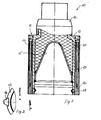
- a warhead 10 partially in longitudinal section, which comprises a warhead housing 11 for receiving a hollow charge 14 having a lining 15 and a detonator 12 connected to the warhead housing 11.
- prism-shaped legs 16 are provided which are mounted in a dovetail groove of the casing 13 of the warhead housing 11 and which are acted upon by helical compression springs 17.
- the legs 16 acted upon by spring pressure are extended in the direction of flight before the warhead 10 hits the surface of the target.
- the legs 16 are locked in the end position by means of bolts 19 which are spring-loaded in the radial direction and which engage in a recess 20 of the leg 16.
- the optimal flight distance is set by pin-shaped legs 16 a, which are extendable in the longitudinal axial direction and are slidably mounted within the casing 13 of the warhead housing 11.
- the pin-shaped legs 16 a are loaded by compression spring 17.
- the pin-shaped legs 16 a are locked by radially spring-loaded bolts 19 which snap into recesses 20 of the pin-shaped legs 16 a after they have reached their end position.
Landscapes
- Engineering & Computer Science (AREA)
- General Engineering & Computer Science (AREA)
- Chemical & Material Sciences (AREA)
- Combustion & Propulsion (AREA)
- Radar Systems Or Details Thereof (AREA)
- Aiming, Guidance, Guns With A Light Source, Armor, Camouflage, And Targets (AREA)
Abstract
Ein Gefechtskopf 10 umfaßt ein Gefechtskopfgehäuse 11 mit einem Zünder 12. Zur Einstellung eines optimalen Zündabstands sind im Gefechtskopfgehäuse 11 ausfahrbar angeordnete Beine 16 vorgesehen, die von Schraubendruckfedern 17 beaufschlagt sind.
Description
- Die Neuerung betrifft einen Gefechtskopf nach dem Oberbegriff des Schutzanspruchs 1.
- Ein derartiger Gefechtskopf ist aus der DE-OS 22 42 930 bekannt. Der bekannte Gefechtskopf umfaßt ein Gefechtskopfgehäuse zur Aufnahme einer Hohlladung sowie einen mit dem Gefechtskopfgehäuse verbundenen Zünder. Der Gefechtskopf wird in einer größeren Anzahl von einem Flugkörper oder Lastengeschoß über ein Zielgebiet transportiert und ausgestoßen, um gebremst oder ungebremst auf das Zielgebiet hinabzusinken. Hohlladungen erreichen bekanntlich ihre maximale Wirkung nur dann, wenn sie in einem bestimmten Mindestabstand über der Zieloberfläche zur Detonation gebracht werden. Bei dem bekannten Gefechtskopf ist daher zur Einhaltung dieses Mindestabstands (stand-off) ein Zündabstandsrohr vorgesehen, das von einer Druckfeder belastet ist und vor dem Zieleufprall teleskopartig ausgefahren wird. Die Druckfeder ist dabei innerhalb der von der Hohlladung gebildeten Höhlung angeordnet, sodaß unter Umständen die Wirksamkeit der Hohlladung beeinträchtigt werden kann.
- Der Neuerung liegt die Aufgabe zugrunde, alternative Mittel zur Einstellung des optimalen Zündabstands anzugeben, die diese Nachteile nicht aufweisen.
- Diese Aufgabe wird durch die in 5chutzanspruch 1 angegebene Neuerung gelöst.
- Vorteilhafte Ausgestaltungen der Neuerung gehen aus den Unteransprüchen hervor.
- Die Neuerung wird nachfolgend, unter Bezug auf die Zeichnung, näher erläutert.Dabei zeigt:
- Fig. 1: einen Gefechtskopf teilweise im Längsschnitt;
- Fig. 2:.eine vergrößerte Detaildarstellung des Gefechtskopfes nach Fig. 1 als Ansicht aus Richtung des Pfeils A;
- Fig. 3:.einen weiteren Gefechtskopf, ebenfalls teilweise im Längsschnitt;
- Fig. 4: eine vergrößerte Detaildarstellung des Gefechtskopfes nach Fig. 3 als Ansicht aus Richtung des Pfeils A.
- Fig. 1 zeigt teilweise im Längsschnitt einen Gefechtskopf 10, der ein Gefechtskopfgehäuse 11 zur Aufnahme einer eine Auskleidung 15 aufweisenden Hohlladung 14 und einen mit dem Gefechtskopfgehäuse 11 verbundenen Zünder 12 umfaßt. Um beim Auftreffen des Gefechtskopfes 10 auf die Zieloberflächeden der Hohlladung 14 einzustellen, sind prismenförmige Beine 16 vorgesehen, die in einer Schwalbenschwanznut des Mantels 13 des Gefechtskopfgehäuses 11 gelagert sind und die von Schraubendruckfedern 17 beaufschlagt sind. Unmittelbar nach dem Ausstoßvorgang aus dem Lastengeschoß und der Trennung der Gefechtsköpfe 10 voneinander werden die durch Federdruck beaufschlagten Beine 16 in Flugrichtung ausgefahren bevor der Gefechtskopf 10 auf der Oberfläche des Ziels aufprallt. Die Beine 16 werden in Endstellung verriegelt und zwar durch in Radialrichtung federbelastete Bolzen 19, die in eine Ausnehmung 20 des Beins 16 eingreifen.
- In einem weiteren Ausführungsbeispiel der Neuerung (Fig. 3, Fig. 4) wird der optimale Flugabstand durch stiftförmige Beine 16 a eingestellt, die in Längsaxialrichtung ausfahrbar innerhalb des Mantels 13 des Gefechtskopfgehäuses 11 gleitbar gelagert aind. Die stiftförmigen Beine 16 a sind durch Druckfeder 17 belastet. Die stiftförmigen Beine 16 a werden durch in Radielrichtung federbelastete Bolzen 19 arretiert, die in Ausnehmungen 20 der stiftförmigen Beine 16 a einrasten, nachdem diese ihre Endstellung erreicht heben.
Claims (5)
1. Gefechtskopf mit einem Gefechtskopfgehäuse zur Aufnahme einer Hohlladung und einem mit dem Gefechtskopf verbundenen Zünder sowie Mitteln zur Einstellung eines optimalen Zündabstands (stand-off), dadurch gekennzeichnet, daß die Mittel zur Einstellung des optimalen Zündabstands aus innerhalb des Gefechtskopfgehäuses (11) ausfahrbar angeordneten Beinen (16, 16 a) bestehen.
2. Gefechtskopf nach Anspruch 1, dadurch gekennzeichn e t , daß die Beine (16, 16 a) durch Schraubendruckfedern (17) beaufschlagt sind.
3. Gefechtskopf nach einem der Ansprüche 1 und 2, dadurch g e - kennzeichnet, daß die Beine (16) prismenartig ausgebildet und in Schmalbenachuanznuten des Mantels (13) des Gefechtskopfgehäuses (11) gelagert sind.
4. Gefechtskopf nach einem der Ansprüche 1 bis 3, dadurch gekennzeichnet, daß die Beine (16 a) stiftförmig ausgebildet und in im Mantel (13) des Gefechtskopfgehäuses (11) angeordneten Bohrungen gelagert sind.
5. Gefechtskopf nach einem der Ansprüche 1 bis 4, dadurch g e - k e n nzeichnet , daß die Beine (16, 16 a) in ihrer Endstellung durch in Radialrichtung federbaufschlagte Bolzen (19) arretierbar sind, die in Ausnehmungen (20) der Beine (16, 16 a) eingreifen.
Applications Claiming Priority (2)
| Application Number | Priority Date | Filing Date | Title |
|---|---|---|---|
| DE8427786U | 1984-09-21 | ||
| DE19848427786 DE8427786U1 (de) | 1984-09-21 | 1984-09-21 | Gefechtskopf |
Publications (1)
| Publication Number | Publication Date |
|---|---|
| EP0178486A1 true EP0178486A1 (de) | 1986-04-23 |
Family
ID=6770910
Family Applications (1)
| Application Number | Title | Priority Date | Filing Date |
|---|---|---|---|
| EP85111930A Withdrawn EP0178486A1 (de) | 1984-09-21 | 1985-09-20 | Gefechtskopf |
Country Status (3)
| Country | Link |
|---|---|
| EP (1) | EP0178486A1 (de) |
| DE (1) | DE8427786U1 (de) |
| ES (1) | ES289140Y (de) |
Cited By (2)
| Publication number | Priority date | Publication date | Assignee | Title |
|---|---|---|---|---|
| EP0375018A3 (de) * | 1988-12-19 | 1992-09-02 | Bofors AB | Geschoss mit mindestens einem Zündabstandshalter |
| US9644925B1 (en) * | 2014-06-19 | 2017-05-09 | The United States Of America As Represented By The Secretary Of The Army | Explosive device for breaching doors and walls |
Citations (5)
| Publication number | Priority date | Publication date | Assignee | Title |
|---|---|---|---|---|
| DE1090559B (de) * | 1959-07-17 | 1960-10-06 | Wasagchemie Ag | Koppelbare Schneidladung |
| FR2357858A1 (fr) * | 1976-07-06 | 1978-02-03 | Messerschmitt Boelkow Blohm | Charge creuse |
| US4178851A (en) * | 1972-03-08 | 1979-12-18 | The United States Of America As Represented By The Secretary Of The Army | Dual purpose munition |
| AT363033B (de) * | 1979-08-16 | 1981-07-10 | Hirtenberger Patronen | Hohlladung mit dreibeingestell |
| DE3343267A1 (de) * | 1983-11-30 | 1985-06-05 | Rheinmetall GmbH, 4000 Düsseldorf | Luftverlastbare einrichtung zur erzeugung eines projektils |
-
1984
- 1984-09-21 DE DE19848427786 patent/DE8427786U1/de not_active Expired
-
1985
- 1985-09-20 EP EP85111930A patent/EP0178486A1/de not_active Withdrawn
- 1985-09-20 ES ES1985289140U patent/ES289140Y/es not_active Expired
Patent Citations (5)
| Publication number | Priority date | Publication date | Assignee | Title |
|---|---|---|---|---|
| DE1090559B (de) * | 1959-07-17 | 1960-10-06 | Wasagchemie Ag | Koppelbare Schneidladung |
| US4178851A (en) * | 1972-03-08 | 1979-12-18 | The United States Of America As Represented By The Secretary Of The Army | Dual purpose munition |
| FR2357858A1 (fr) * | 1976-07-06 | 1978-02-03 | Messerschmitt Boelkow Blohm | Charge creuse |
| AT363033B (de) * | 1979-08-16 | 1981-07-10 | Hirtenberger Patronen | Hohlladung mit dreibeingestell |
| DE3343267A1 (de) * | 1983-11-30 | 1985-06-05 | Rheinmetall GmbH, 4000 Düsseldorf | Luftverlastbare einrichtung zur erzeugung eines projektils |
Cited By (2)
| Publication number | Priority date | Publication date | Assignee | Title |
|---|---|---|---|---|
| EP0375018A3 (de) * | 1988-12-19 | 1992-09-02 | Bofors AB | Geschoss mit mindestens einem Zündabstandshalter |
| US9644925B1 (en) * | 2014-06-19 | 2017-05-09 | The United States Of America As Represented By The Secretary Of The Army | Explosive device for breaching doors and walls |
Also Published As
| Publication number | Publication date |
|---|---|
| DE8427786U1 (de) | 1985-05-15 |
| ES289140Y (es) | 1986-10-01 |
| ES289140U (es) | 1986-03-01 |
Similar Documents
| Publication | Publication Date | Title |
|---|---|---|
| EP0255130B1 (de) | Zünder für eine projektilbildende Ladung | |
| EP0101795B1 (de) | Sprenggeschoss mit verbesserter Splitterwirkung | |
| DE69509332T2 (de) | Geschoss für die Zerstörung von harten Zielen, die tief vergraben sind | |
| DE3934042C2 (de) | ||
| DE2907308C2 (de) | Geschoß mit mindestens einem ausstoßbaren Tochtergeschoß | |
| DE2900802C1 (de) | Gefechtskopf gegen befestigte oder gepanzerte Ziele,insbesondere zum Beschaedigen von Startbahnen,Fahrbahndecken,Bunkerwaenden oder dergleichen | |
| DE69120954T2 (de) | Vorrichtung zum abfeuern eines geschosses | |
| DE3715085C2 (de) | Lenkwaffengeschoß | |
| DE3781874T2 (de) | Bombe mit splitterhuelle. | |
| DE1578457B2 (de) | Sicherungseinrichtung fuer aufschlagzuender | |
| WO1986005581A1 (fr) | Moyen de propulsion pour reduire la trainee de culot d'un engin ballistique | |
| EP0918209B1 (de) | Geschoss mit programmierbarem Zeitzünder | |
| EP0435083B1 (de) | Einstellbarer Abstandshalter auf einem Hohlladungsgefechtskopf, umschaltbar für Tiefen- oder Seitenwirkung | |
| DE3703773A1 (de) | Geschoss, insbesondere moersergeschoss | |
| EP0187932A1 (de) | Vorrohrsicherung für Übungsmunition | |
| EP0184622B1 (de) | Gefechtskopf | |
| WO1991010877A1 (de) | Patrone, insbesondere granatpatrone | |
| EP0175379A1 (de) | Gefechtskopf | |
| DE3609865C1 (de) | Gefechtskopf mit einer Hohlladung | |
| DE3640485C1 (en) | Bomblet (submunition) | |
| DE8427786U1 (de) | Gefechtskopf | |
| DE7928929U1 (de) | Aufschlagzuendkopf fuer ein explosivgeschoss | |
| DE19758457B3 (de) | Gefechtskopf | |
| EP0185151A2 (de) | Gefechtskopf | |
| DE2946156C2 (de) |
Legal Events
| Date | Code | Title | Description |
|---|---|---|---|
| PUAI | Public reference made under article 153(3) epc to a published international application that has entered the european phase |
Free format text: ORIGINAL CODE: 0009012 |
|
| AK | Designated contracting states |
Kind code of ref document: A1 Designated state(s): DE FR GB IT NL SE |
|
| 17P | Request for examination filed |
Effective date: 19860318 |
|
| 17Q | First examination report despatched |
Effective date: 19870506 |
|
| STAA | Information on the status of an ep patent application or granted ep patent |
Free format text: STATUS: THE APPLICATION IS DEEMED TO BE WITHDRAWN |
|
| 18D | Application deemed to be withdrawn |
Effective date: 19881213 |
|
| RIN1 | Information on inventor provided before grant (corrected) |
Inventor name: SCHUTKIN,CHARLOTTE Inventor name: GUENTHNER,FRIEDHELM |