EP0178653A2 - Akustooptische Bildformung - Google Patents
Akustooptische Bildformung Download PDFInfo
- Publication number
- EP0178653A2 EP0178653A2 EP85113136A EP85113136A EP0178653A2 EP 0178653 A2 EP0178653 A2 EP 0178653A2 EP 85113136 A EP85113136 A EP 85113136A EP 85113136 A EP85113136 A EP 85113136A EP 0178653 A2 EP0178653 A2 EP 0178653A2
- Authority
- EP
- European Patent Office
- Prior art keywords
- image sensor
- image
- pressure wave
- acoustooptic
- light
- Prior art date
- Legal status (The legal status is an assumption and is not a legal conclusion. Google has not performed a legal analysis and makes no representation as to the accuracy of the status listed.)
- Granted
Links
- 230000015572 biosynthetic process Effects 0.000 title description 4
- 230000005855 radiation Effects 0.000 claims abstract description 51
- 230000003287 optical effect Effects 0.000 claims abstract description 18
- 239000000463 material Substances 0.000 claims abstract description 17
- 238000001454 recorded image Methods 0.000 claims abstract description 9
- 238000000034 method Methods 0.000 claims description 31
- OAICVXFJPJFONN-UHFFFAOYSA-N Phosphorus Chemical compound [P] OAICVXFJPJFONN-UHFFFAOYSA-N 0.000 claims description 11
- 239000011521 glass Substances 0.000 claims description 11
- 239000011159 matrix material Substances 0.000 claims description 4
- 230000004936 stimulating effect Effects 0.000 claims 2
- 239000002033 PVDF binder Substances 0.000 description 4
- 229920002981 polyvinylidene fluoride Polymers 0.000 description 4
- 230000008569 process Effects 0.000 description 3
- 229910019142 PO4 Inorganic materials 0.000 description 2
- ZLMJMSJWJFRBEC-UHFFFAOYSA-N Potassium Chemical compound [K] ZLMJMSJWJFRBEC-UHFFFAOYSA-N 0.000 description 2
- VYPSYNLAJGMNEJ-UHFFFAOYSA-N Silicium dioxide Chemical compound O=[Si]=O VYPSYNLAJGMNEJ-UHFFFAOYSA-N 0.000 description 2
- MCMNRKCIXSYSNV-UHFFFAOYSA-N Zirconium dioxide Chemical compound O=[Zr]=O MCMNRKCIXSYSNV-UHFFFAOYSA-N 0.000 description 2
- 230000001464 adherent effect Effects 0.000 description 2
- 229920001577 copolymer Polymers 0.000 description 2
- 239000013078 crystal Substances 0.000 description 2
- 230000001419 dependent effect Effects 0.000 description 2
- 125000000664 diazo group Chemical group [N-]=[N+]=[*] 0.000 description 2
- 230000000694 effects Effects 0.000 description 2
- NBIIXXVUZAFLBC-UHFFFAOYSA-K phosphate Chemical compound [O-]P([O-])([O-])=O NBIIXXVUZAFLBC-UHFFFAOYSA-K 0.000 description 2
- 239000010452 phosphate Substances 0.000 description 2
- 229920000131 polyvinylidene Polymers 0.000 description 2
- 229910052700 potassium Inorganic materials 0.000 description 2
- 239000011591 potassium Substances 0.000 description 2
- AVTYONGGKAJVTE-OLXYHTOASA-L potassium L-tartrate Chemical compound [K+].[K+].[O-]C(=O)[C@H](O)[C@@H](O)C([O-])=O AVTYONGGKAJVTE-OLXYHTOASA-L 0.000 description 2
- LJCNRYVRMXRIQR-OLXYHTOASA-L potassium sodium L-tartrate Chemical compound [Na+].[K+].[O-]C(=O)[C@H](O)[C@@H](O)C([O-])=O LJCNRYVRMXRIQR-OLXYHTOASA-L 0.000 description 2
- 229940111695 potassium tartrate Drugs 0.000 description 2
- 239000001472 potassium tartrate Substances 0.000 description 2
- 235000011005 potassium tartrates Nutrition 0.000 description 2
- 229910052709 silver Inorganic materials 0.000 description 2
- 239000004332 silver Substances 0.000 description 2
- -1 silver halide Chemical class 0.000 description 2
- 235000011006 sodium potassium tartrate Nutrition 0.000 description 2
- GGCZERPQGJTIQP-UHFFFAOYSA-N sodium;9,10-dioxoanthracene-2-sulfonic acid Chemical compound [Na+].C1=CC=C2C(=O)C3=CC(S(=O)(=O)O)=CC=C3C(=O)C2=C1 GGCZERPQGJTIQP-UHFFFAOYSA-N 0.000 description 2
- 230000000638 stimulation Effects 0.000 description 2
- FUJCRWPEOMXPAD-UHFFFAOYSA-N Li2O Inorganic materials [Li+].[Li+].[O-2] FUJCRWPEOMXPAD-UHFFFAOYSA-N 0.000 description 1
- KKCBUQHMOMHUOY-UHFFFAOYSA-N Na2O Inorganic materials [O-2].[Na+].[Na+] KKCBUQHMOMHUOY-UHFFFAOYSA-N 0.000 description 1
- 230000005260 alpha ray Effects 0.000 description 1
- PNEYBMLMFCGWSK-UHFFFAOYSA-N aluminium oxide Inorganic materials [O-2].[O-2].[O-2].[Al+3].[Al+3] PNEYBMLMFCGWSK-UHFFFAOYSA-N 0.000 description 1
- QVQLCTNNEUAWMS-UHFFFAOYSA-N barium oxide Inorganic materials [Ba]=O QVQLCTNNEUAWMS-UHFFFAOYSA-N 0.000 description 1
- 239000000919 ceramic Substances 0.000 description 1
- 229910052801 chlorine Inorganic materials 0.000 description 1
- 229910052681 coesite Inorganic materials 0.000 description 1
- 229910052802 copper Inorganic materials 0.000 description 1
- 229910052593 corundum Inorganic materials 0.000 description 1
- 229910052906 cristobalite Inorganic materials 0.000 description 1
- 238000001514 detection method Methods 0.000 description 1
- 238000010586 diagram Methods 0.000 description 1
- XUCJHNOBJLKZNU-UHFFFAOYSA-M dilithium;hydroxide Chemical compound [Li+].[Li+].[OH-] XUCJHNOBJLKZNU-UHFFFAOYSA-M 0.000 description 1
- 238000010894 electron beam technology Methods 0.000 description 1
- 229910052731 fluorine Inorganic materials 0.000 description 1
- 230000005251 gamma ray Effects 0.000 description 1
- 150000002484 inorganic compounds Chemical class 0.000 description 1
- 229910010272 inorganic material Inorganic materials 0.000 description 1
- 230000001678 irradiating effect Effects 0.000 description 1
- YEXPOXQUZXUXJW-UHFFFAOYSA-N lead(II) oxide Inorganic materials [Pb]=O YEXPOXQUZXUXJW-UHFFFAOYSA-N 0.000 description 1
- 238000005259 measurement Methods 0.000 description 1
- 238000012986 modification Methods 0.000 description 1
- 230000004048 modification Effects 0.000 description 1
- 238000010895 photoacoustic effect Methods 0.000 description 1
- 238000004867 photoacoustic spectroscopy Methods 0.000 description 1
- 230000000750 progressive effect Effects 0.000 description 1
- 230000010349 pulsation Effects 0.000 description 1
- 230000004044 response Effects 0.000 description 1
- 239000004065 semiconductor Substances 0.000 description 1
- 239000000377 silicon dioxide Substances 0.000 description 1
- 230000003595 spectral effect Effects 0.000 description 1
- 229910052682 stishovite Inorganic materials 0.000 description 1
- 239000000126 substance Substances 0.000 description 1
- 229910052905 tridymite Inorganic materials 0.000 description 1
- WFKWXMTUELFFGS-UHFFFAOYSA-N tungsten Chemical compound [W] WFKWXMTUELFFGS-UHFFFAOYSA-N 0.000 description 1
- 229910052721 tungsten Inorganic materials 0.000 description 1
- 239000010937 tungsten Substances 0.000 description 1
- 229910052724 xenon Inorganic materials 0.000 description 1
- FHNFHKCVQCLJFQ-UHFFFAOYSA-N xenon atom Chemical compound [Xe] FHNFHKCVQCLJFQ-UHFFFAOYSA-N 0.000 description 1
- 229910001845 yogo sapphire Inorganic materials 0.000 description 1
Images


Classifications
-
- G—PHYSICS
- G03—PHOTOGRAPHY; CINEMATOGRAPHY; ANALOGOUS TECHNIQUES USING WAVES OTHER THAN OPTICAL WAVES; ELECTROGRAPHY; HOLOGRAPHY
- G03C—PHOTOSENSITIVE MATERIALS FOR PHOTOGRAPHIC PURPOSES; PHOTOGRAPHIC PROCESSES, e.g. CINE, X-RAY, COLOUR, STEREO-PHOTOGRAPHIC PROCESSES; AUXILIARY PROCESSES IN PHOTOGRAPHY
- G03C5/00—Photographic processes or agents therefor; Regeneration of such processing agents
- G03C5/16—X-ray, infrared, or ultraviolet ray processes
-
- G—PHYSICS
- G01—MEASURING; TESTING
- G01N—INVESTIGATING OR ANALYSING MATERIALS BY DETERMINING THEIR CHEMICAL OR PHYSICAL PROPERTIES
- G01N21/00—Investigating or analysing materials by the use of optical means, i.e. using sub-millimetre waves, infrared, visible or ultraviolet light
- G01N21/17—Systems in which incident light is modified in accordance with the properties of the material investigated
- G01N21/1702—Systems in which incident light is modified in accordance with the properties of the material investigated with opto-acoustic detection, e.g. for gases or analysing solids
-
- G—PHYSICS
- G01—MEASURING; TESTING
- G01T—MEASUREMENT OF NUCLEAR OR X-RADIATION
- G01T1/00—Measuring X-radiation, gamma radiation, corpuscular radiation, or cosmic radiation
- G01T1/16—Measuring radiation intensity
- G01T1/20—Measuring radiation intensity with scintillation detectors
- G01T1/2012—Measuring radiation intensity with scintillation detectors using stimulable phosphors, e.g. stimulable phosphor sheets
- G01T1/2014—Reading out of stimulable sheets, e.g. latent image
-
- G—PHYSICS
- G03—PHOTOGRAPHY; CINEMATOGRAPHY; ANALOGOUS TECHNIQUES USING WAVES OTHER THAN OPTICAL WAVES; ELECTROGRAPHY; HOLOGRAPHY
- G03B—APPARATUS OR ARRANGEMENTS FOR TAKING PHOTOGRAPHS OR FOR PROJECTING OR VIEWING THEM; APPARATUS OR ARRANGEMENTS EMPLOYING ANALOGOUS TECHNIQUES USING WAVES OTHER THAN OPTICAL WAVES; ACCESSORIES THEREFOR
- G03B42/00—Obtaining records using waves other than optical waves; Visualisation of such records by using optical means
- G03B42/06—Obtaining records using waves other than optical waves; Visualisation of such records by using optical means using ultrasonic, sonic or infrasonic waves
Definitions
- the present invention relates to a method of and a device for acoustooptically forming images by applying light to a recording medium having different optical densities representative of an image to generate an image- dependent pressure wave.
- Images recorded as optical density differences on a recording medium can be acoustooptically reproduced by irradiating the recording medium with pulses of light, detecting pressure fluctuations or a pressure wave generated from the recording medium in synchronism with the light pulses applied to the recording medium, and utilizing a detected electric signal indicative of the pressure wave as an image signal.
- Another object of the present invention to provide a novel device for acoustooptically forming images.
- Still another object of the present invention is to provide a novel camera utilizing the acoustooptic effect in forming images.
- a method of forming an acoustooptic image by using a plate-like image sensor capable of increasing its optical density upon exposure to a radiation comprising the steps of exposing the image sensor to a radiation bearing image information to record the image information on the image sensor, applying pulsed light to the image sensor to enable the same to generate a pressure wave commensurate with the recorded image information, detecting the pressure wave in synchronism with the pulsed light to convert the pressure wave into an electric signal, and reproducing an image from the electric signal.
- a device for forming an acoustooptic image comprising a plate-like image sensor capable of increasing its optical density upon exposure to a radiation, first exposing means for exposing the image sensor to a radiation bearing image information to record the image information on the image sensor, second exposing means for applying pulsed light to the image sensor to enable the same to generate a pressure wave commensurate with the recorded image information, detecting means for detecting the pressure wave in synchronism with the pulsed light to convert the pressure wave into an electric signal, and image reproducing means for reproducing an image from the electric signal.
- an acoustooptic camera comprising a light-shielding housing for accommodating a plate-like image sensor capable of increasing its optical density upon exposure to a radiation, the light-shielding housing having means for exposing the image sensor to a radiation bearing image information to record the image information on the image sensor, second exposing means in the light-shielding housing for applying pulsed light to the image sensor to enable the same to generate a pressure wave commensurate with the recorded image information, and detecting means in the light-shielding housing for detecting the pressure wave in synchronism with the pulsed light to convert the pressure wave into an electric signal.
- the image derived from the electric signal may be displayed on a CRT, or recorded on a magnetic tape or a magnetic disc, or reproduced on a photographic material.
- the pressure wave may be detected by a microphone, a bolometer, a piezoelectric device, or an electrostrictive device.
- Exposure of the image sensor to the pulsed light may be effected by scanning the image sensor with a light beam spot through two-dimensional scanning process, or with a one-dimensional fan beam, or by applying the pulsed light to the image sensor over its entire surface.
- the image sensor may be in the form of a stimulable phosphor sheet, a diazo film, a silver-salt film, or a photochromic material.
- Figure 1 shows the essential steps of a method of accustooptically forming an image according to the present invention.
- the method of the invention is basically composed of four steps: primary exposure, secondary exposure, pressure wave detection, and image formation.
- a plate-like image sensor which will exhibit an increase in optical density upon exposure to a radiation such as visible light, an X-ray, an electron beam, an ultraviolet ray, an ⁇ -ray, a 8-ray, or a ⁇ -ray. and the plate-like image sensor is exposed to the radiation carrying image information so as to record the image information as optical density differences on the image sensor.
- the image sensor is exposed to pulses of light to enable the image sensor to generate pressure fluctuations or a pressure wave dependent on the recorded image information in synchronism with the applied pulses of light.
- the third step detects the pressure wave with a sound detector such as a microphone.
- an electric signal generated by the microphone in proportion to the detected pressure wave is utilized to reproduce the image information on an image reproducing device or material.
- a plate-like image sensor 1 employed as an image carrier capable of recording or storing radiation image information may comprise a stimulable phosphor (as disclosed in Japanese Unexamined Patent Publication No. 55(1980)-12429), a diazo film, a silver-salt film, or a sheet of photochromic glass.
- An object 2 such as a film carrying an original image to be recorded is placed over the image sensor 1.
- the image sensor 1 is then exposed to a radiation such as an X-ray or visible light emitted from a radiation source 3 and transmitted through the object 2.
- the radiation image of the object 2 is now stored or recorded on the image sensor 1.
- the image sensor 1 is placed on a pressure wave guide 4 in intimate contact therewith through the intermediary of an adherent layer lA.
- the image sensor 1 is scanned in the directions of the arrow A by a laser beam 5A emitted from a laser beam source 5 above the image sensor 1 and deflected by a galvanometer mirror 6 ( main scanning).
- the image sensor 1 is moved in the direction of the arrow B (sub-scanning). Therefore, the image sensor 1 is two-dimensionally scanned by the laser beam 5A.
- a pressure wave or pressure fluctuations generated by the image sensor 1 and transmitted through the pressure wave guide 4 are collected by a microphone 7 positioned below the pressure wave guide 4.
- the microphone 7 produces an output electric signal which is applied to an output signal storage circuit 8.
- the output signal storage circuit 8 may be replaced with an image reproducing device capable of reproducing the image from the image signal, or with a recording device employing a magnetic tape, a magnetic disk, or other magnetic recording mediums.
- a laser beam 10A emitted from a laser beam source 10 is modulated by the image signal 9 from the output signal storage circuit 8.
- the modulated laser beam 10A is then deflected by a galvanometer mirror 13 to scan a recording medium 12 to reproduce the image information thereon.
- the photochromic glass which the image sensor may be made of, is widely used as a material of spectacle lenses.
- the photochromic glass is described in detail in Japanese Patent Publication No. 56(1981)-9465; and various other publications such as "Photochromic glass and inorganic compound” by Sumio Sakuhana, Chemical Industry 62, p. 189 - 194 (1978); "Photochromic glass” by Takeo Ichimura, Ceramic Technology Collection p. 423 - 429 (1979), Industrial Technology Center; "Inorganic photochromic materials - compound and glass - " by Sumio Sakuhana, Material Chemistry 8, p. 191 - 202 (1971), for example.
- the microphone 7 may be replaced with a bolometer for detecting thermal energy produced in proportion to the pressure wave, or an electrostrictive device, or a piezoelectric device capable of electrically detecting a pressure.
- the piezoelectric device is composed of a piezoelectric material such as crystal, Rochelle salt, potassium tartrate (DKT), potassium primary phosphate (KDT), PZT, polyvinylidene fluoride (PVDF), or polyvinylidene cyanide copolymer [P(VDCN VAc)].
- Figures 4A and 4B show the manner in which pulses of light are applied in the form of a fan beam 15 to the image sensor 1, and a pressure wave generated by the image sensor 1 in response to the applied light pulses is detected by a one-dimensional array detector 16 disposed beneath the image sensor 1.
- the fan beam 15 together with the array detector 6, and the image sensor 1 are moved with respect to each other for two-dimensional scanning of the image sensor 1.
- the fan beam 15 and the array detector 6 may be moved and the image sensor 1 may be fixed, or vice versa.
- Figure 5 illustrates another arrangement in which a pressure-wave detector 20 is placed coextensively below the image sensor 1 in intimate contact therewith, and a matrix of electrodes 21 is disposed on the entire lower surface of the detector 20.
- the electrodes 21 can therefore detect a pressure wave generated by the image sensor 1 when the entire surface of the image sensor 1 is exposed to pulses of light.
- the image sensor 1 may be scanned by a beam spot or a fan beam for secondary exposure.
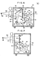
- FIG. 6 shows an acoustooptic camera according to an embodiment of the present invention.
- the acoustooptic camera generally denoted at 30, is designed primarily for photographing the radiation image of an object 31 such as a human body.
- the acoustooptic camera 30 includes a light-shielding housing 32 accommodating therein a plate-shaped image sensor 33, an exposure assembly 34 for two-dimensionally scanning the image sensor 33 with light transmitted via a movable mirror 35, a pressure-wave detector 36, and an erase light source 37.
- the plate-like image sensor 33 may comprise a stimulable phosphor sheet as disclosed in Japanese Unexamined Patent Publication No. 55(1980)-12429.
- the stimulable phosphor sheet may be in the form of a layer of stimulable phosphor deposited on a sheet-like support, or a sheet of self-supporting stimulable phosphor.
- the exposure assembly 34 comprises a laser 38 such as an He - Ne laser or a semiconductor laser, and two light deflectors 39, 40 for deflecting a laser beam 41 emitted as light from the laser 38 into mutually perpendicular directions.
- the laser beam 41 deflected by the light deflectors 39, 40 is reflected by the movable mirror 35 to impinge on the image sensor 33 for dimensionally scanning the same.
- Each of the light deflectors 39, 40 may comprise a known light deflector such as a galvanometer mirror, a polygonal mirror, an acoustooptic deflector.
- the laser 38 is driven by a driver circuit 42 which is controlled by a control signal Sl from a control circuit 43 for energizing the laser 38 to emit laser pulses.
- the driver circuit 42 may comprise an acoustooptic modulator or a modulator for directly modulating the laser 41 emitted by the laser 38.
- the light deflectors 39, 40 are controlled by respective control signals S2, S3 generated by the control circuit 43.
- the pressure-wave detector 36 has a wave guide 44 against which the image sensor 33 is held through an adherent member 45, a microphone 46 disposed closely to the wave guide 44, and a signal processor 47 for processing an electric pressure-wave (sound) signal issued from the microphone 46.
- the erase light source 37 emits light 48 in the stimulation wavelength region as that of the light to be applied to the stimulable phosphor.
- the light emitted from the erase light source 37 is reflected by the movable mirror 35 to fall on the image sensor 33.
- the erase light source 37 may comprise a xenon flash lamp, a tungsten lamp, an infrared lamp, a fluorescent lamp, or a laser source.
- the movable mirror 35 is moved angularly by a driver means (not shown) between the solid-line position and the dotted-line position.
- the light-shielding housing 32 is made of a material capable of shielding ambient light in the stimulation wavelength region of the stimulable phosphor and also of transmitting a radiation for recording the image of the object 31 on the image sensor 33.
- the acoustooptic camera 30 operates to record the image of the object 31 on the image sensor 33 as follows:
- the acoustooptic camera 30 is disposed to face the image sensor 33 toward a radiation source 49 such as an X-ray tube.
- the object 31 is positioned between the camera 30 and the radiation source 49, and the movable mirror 35 is retracted from the solid-line position in front of the image sensor 33 toward the dotted-line position.
- the radiation source 49 When the radiation source 49 is energized, it emits a radiation 50 which passes through the object 31.
- the radiation 50 which bears the image of the object 31 them falls on the image sensor 33 to record the radiation image thereon.
- the radiation image recorded on the image sensor 33 will then be converted into an electric image signal in the following manner: First, the movable mirror 35 is angularly moved to the solid-line position, and then the pulsed laser beam 41 emitted from the laser 38 is deflected by the light deflectors 39, 40 for two-dimensionally scanning the image sensor 33.
- the image sensor 33 is scanned by the pulsed laser beam 4l, it generates a pressure wave or pressure pulsations commensurate with the image information stored therein.
- the generated pressure wave is detected by the microphone 46 which produces an electric pressure-wave signal S5 applied to the signal processor 47.
- the signal processor 47 is supplied with a synchronizing signal S4 generated by the control circuit 43 in synchronism with the pulsed laser beam 41 for processing the pressure-wave signal S5 thereby to issue an electric image signal S6 representative of the radiation image stored in the image sensor 33.
- the image signal S6 can be used to display the radiation image on a display such as a CRT or record the radiation image on a photosensitive material through a light-scanning recorder. Prior to such image reproduction, the image signal S6 may temporarily be recorded on an information storage medium such as a magnetic tape, a magnetic disc, or an optical disc.
- the erase light source 37 is energized to cause the image sensor 33 to be exposed to the erasing light 48 from the erase light source 37 via the movable mirror 35. Any remanent radiation image which may have remained on the image sensor 33 after the pressure wave has been generated and detected can therefore be discharged from the image sensor 33, which can then be reused. A new radiation image can thereafter be recorded on the image sensor 33 and reproduced therefrom by repeating the foregoing process.
- the microphone 46 positioned in the vicinity of the image sensor 33 may be replaced with a bolometer for detecting thermal energy emittted from the image sensor 33 in proportion to the pressure wave, or an electrostrictive device, or a piezoelectric device capable of electrically detecting pressure.
- the piezoelectric device can be composed of a piezoelectric material such as crystal, Rochelle salt, potassium tartrate (DKT), potassium primary phosphate (KDT), PZT, polyvinylidene fluoride (PVDF), or polyvinylidene cyanide copolymer [P(VDCN VAc)].
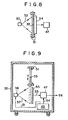
- FIGS 7 and 8 illustrate an acoustooptic camera according to another embodiment of the present invention.
- the image sensor 33 is vertically movable by a plurality of driver rollers 51 between an upper position indicated by the solid line and a lower position indicated by the dotted line. After the radiation image of the object 31 has been recorded on the image sensor 33, the image sensor 33 is moved from the upper position downwardly to the lower position by the drive rollers 40. While the image sensor 33 is moving downwardly, a pulsed fan beam 52 is applied by a fan beam generator 53 to the image sensor 33, which then generates a pressure wave that is detected by a one-dimensional pressure-wave detector 54 comprising an array of piezoelectric devices or electrostrictive devices.
- the one-dimensional array detector 54 issues an electric pressure-wave signal S5 which is then processed by the signal processor 47 into an image signal S6 for reproducing the radiation image as a visible image.
- a two-dimensional pressure-wave detector 55 comprising a matrix of piezoelectric devices or electrostrictive devices is employed to detect the pressure wave generated by the image sensor 33.
- a light source 56 applies pulsed light 57 in a two-dimensional pattern to the image sensor 33.
- the image sensor 33 with a recorded radiation image stored therein is moved by the drive rollers 51 from the upper solid-line position toward the lower dotted-line position, the image sensor 33 is exposed to the pulsed light from the stimulating-light source 56.
- the light source 56 is energized again to apply the light to the image sensor 33 to discharge any residual radiation energy from the image sensor 33 so that the image sensor 33 can be recycled.
- the light source 56 thus doubles as an erase light source.
- the image sensor 55 may be scanned by a laser beam spot or a fan laser beam.
- the image sensor 33 is recycled by repeating the steps of recording a radiation image on the image sensor 33, reading the recorded radiation image from the image sensor 33, and erasing any residual radiation energy from the image sensor 33.
- the image sensor 33 may be replaced with a new image sensor each time a new radiation image is to be recorded, and the residual radiation energy may be erased from the image sensor 33 by a separate erase device.
- FIG. 10 shows an acoustooptic camera according to a still further embodiment of the present invention.
- the acoustooptic camera can record an ordinary optical image.
- the acoustooptic camera 110 has an image sensor 113 made of photochromic glass containing silver halide for increasing the optical density upon exposure to light.
- the acoustooptic camera 110 also has a lens 120 and a shutter 121 which are positioned in confronting relation to the image sensor 113. When the shutter 121 is opened with the movable mirror 35 positioned as indicated by the dotted line, the image of an object 111, borne by light 131, is formed by the lens 120 on the image sensor 113.
- the image sensor 113 now stores the optical image of the object 113 thereon.
- the stored optical image can be read from the image sensor 113 by the same arrangement as that of the camera 30 shown in Figure 6 to produce an image signal S6 representative of the recorded optical image.
- the image signal S6 can then be used to reproduce the image of the object 111 on a CRT or otherwise store the image on a suitable recording medium.
- the image sensor 113 is exposed to the erasing light 48 emitted from the erase light source 37 to discharge a visible-light energy from the image sensor 113 to allow the same to be recycled.
- the image sensor l13 may be vertically moved between a recording position and a read-out position as shown in Figure 7 or 9.
- the photochromic glass containing silver halide which the image sensor 113 is made of, may be formed of SiO 2 , Na20 , Al 2 O 3' ⁇ 2 O 3 , Li 2 O, PbO, BaO, ZrO 2 , Ag, Br, Cl, F, and Cu.
Landscapes
- Physics & Mathematics (AREA)
- General Physics & Mathematics (AREA)
- Health & Medical Sciences (AREA)
- Life Sciences & Earth Sciences (AREA)
- Biochemistry (AREA)
- Analytical Chemistry (AREA)
- Chemical & Material Sciences (AREA)
- General Health & Medical Sciences (AREA)
- Immunology (AREA)
- Pathology (AREA)
- High Energy & Nuclear Physics (AREA)
- Molecular Biology (AREA)
- Spectroscopy & Molecular Physics (AREA)
- Conversion Of X-Rays Into Visible Images (AREA)
- Transforming Light Signals Into Electric Signals (AREA)
Applications Claiming Priority (6)
| Application Number | Priority Date | Filing Date | Title |
|---|---|---|---|
| JP216903/84 | 1984-10-16 | ||
| JP59216903A JPS6195300A (ja) | 1984-10-16 | 1984-10-16 | 光音響画像形成方法および装置 |
| JP60077206A JPS61235830A (ja) | 1985-04-11 | 1985-04-11 | 光音響カメラ |
| JP77206/85 | 1985-04-11 | ||
| JP105579/85 | 1985-05-17 | ||
| JP60105579A JPS61264859A (ja) | 1985-05-17 | 1985-05-17 | 光音響画像形成方法および装置 |
Publications (3)
| Publication Number | Publication Date |
|---|---|
| EP0178653A2 true EP0178653A2 (de) | 1986-04-23 |
| EP0178653A3 EP0178653A3 (en) | 1987-11-19 |
| EP0178653B1 EP0178653B1 (de) | 1990-02-28 |
Family
ID=27302364
Family Applications (1)
| Application Number | Title | Priority Date | Filing Date |
|---|---|---|---|
| EP85113136A Expired EP0178653B1 (de) | 1984-10-16 | 1985-10-16 | Akustooptische Bildformung |
Country Status (3)
| Country | Link |
|---|---|
| US (1) | US4727420A (de) |
| EP (1) | EP0178653B1 (de) |
| DE (1) | DE3576219D1 (de) |
Cited By (1)
| Publication number | Priority date | Publication date | Assignee | Title |
|---|---|---|---|---|
| EP0282234A1 (de) * | 1987-03-03 | 1988-09-14 | Elizabeth May Dowling | Optoakustische Spektroskopie |
Families Citing this family (9)
| Publication number | Priority date | Publication date | Assignee | Title |
|---|---|---|---|---|
| US6405069B1 (en) | 1996-01-31 | 2002-06-11 | Board Of Regents, The University Of Texas System | Time-resolved optoacoustic method and system for noninvasive monitoring of glucose |
| US5840023A (en) * | 1996-01-31 | 1998-11-24 | Oraevsky; Alexander A. | Optoacoustic imaging for medical diagnosis |
| US6309352B1 (en) | 1996-01-31 | 2001-10-30 | Board Of Regents, The University Of Texas System | Real time optoacoustic monitoring of changes in tissue properties |
| WO2001010295A1 (en) | 1999-08-06 | 2001-02-15 | The Board Of Regents Of The University Of Texas System | Optoacoustic monitoring of blood oxygenation |
| US6751490B2 (en) | 2000-03-01 | 2004-06-15 | The Board Of Regents Of The University Of Texas System | Continuous optoacoustic monitoring of hemoglobin concentration and hematocrit |
| US6651481B1 (en) | 2001-10-12 | 2003-11-25 | The United States Of America As Represented By The United States National Aeronautics And Space Administration | Method and apparatus for characterizing pressure sensors using modulated light beam pressure |
| US6628451B2 (en) * | 2002-02-14 | 2003-09-30 | Jaswinder S Sandhu | Acousto-optic reflection-active imaging |
| AU2004233870B2 (en) * | 2003-04-24 | 2009-11-05 | The Board Of Regents Of The University Of Texas System | Noninvasive blood analysis by optical probing of the veins under the tongue |
| US7495369B2 (en) * | 2005-05-26 | 2009-02-24 | Araz Yacoubian | Broadband imager |
Family Cites Families (7)
| Publication number | Priority date | Publication date | Assignee | Title |
|---|---|---|---|---|
| US3975637A (en) * | 1973-10-23 | 1976-08-17 | Matsushita Electric Industrial Co., Ltd. | Device for storage and display of a radiation image |
| US4092174A (en) * | 1976-01-30 | 1978-05-30 | Pilkington Brothers Limited | Photochromic glasses |
| JPS5512429A (en) * | 1978-07-12 | 1980-01-29 | Fuji Photo Film Co Ltd | Radioactive image reader |
| US4255971A (en) * | 1978-11-01 | 1981-03-17 | Allan Rosencwaig | Thermoacoustic microscopy |
| US4267732A (en) * | 1978-11-29 | 1981-05-19 | Stanford University Board Of Trustees | Acoustic microscope and method |
| DE2927142C2 (de) * | 1979-07-05 | 1984-06-28 | Pfaff Industriemaschinen Gmbh, 6750 Kaiserslautern | Mehrkopfstickmaschine |
| JPS58182572A (ja) * | 1982-04-20 | 1983-10-25 | Toshiba Corp | 二次元放射線検出器 |
-
1985
- 1985-10-16 US US06/787,850 patent/US4727420A/en not_active Expired - Lifetime
- 1985-10-16 EP EP85113136A patent/EP0178653B1/de not_active Expired
- 1985-10-16 DE DE8585113136T patent/DE3576219D1/de not_active Expired - Lifetime
Cited By (1)
| Publication number | Priority date | Publication date | Assignee | Title |
|---|---|---|---|---|
| EP0282234A1 (de) * | 1987-03-03 | 1988-09-14 | Elizabeth May Dowling | Optoakustische Spektroskopie |
Also Published As
| Publication number | Publication date |
|---|---|
| US4727420A (en) | 1988-02-23 |
| EP0178653A3 (en) | 1987-11-19 |
| EP0178653B1 (de) | 1990-02-28 |
| DE3576219D1 (de) | 1990-04-05 |
Similar Documents
| Publication | Publication Date | Title |
|---|---|---|
| US4727420A (en) | Acoustooptic image formation | |
| JP2670632B2 (ja) | 光走査装置 | |
| US5654556A (en) | Radiation image read-out method and apparatus and stimulable phosphor sheet for the same | |
| JPS63261315A (ja) | 光学ユニツト | |
| US4914295A (en) | Radiation image read-out and image signal storing apparatus | |
| US5051589A (en) | Stimulable phosphor sheet and energy subtraction processing method using the same | |
| JPS60125056A (ja) | 放射線画像情報読取装置 | |
| JP2601479B2 (ja) | 光ビーム走査装置 | |
| US4700071A (en) | Method of recording and reproducing an electron microscope image | |
| JP3273480B2 (ja) | 放射線画像読取装置 | |
| US4952806A (en) | Noise erasing method for stimulable phosphor sheets | |
| US4873440A (en) | Electron microscope image output method and apparatus | |
| JPS61235830A (ja) | 光音響カメラ | |
| JPS60120346A (ja) | 放射線画像情報記録読取方法および装置 | |
| JPS62145634A (ja) | 透過型電子顕微鏡 | |
| JP2557213B2 (ja) | 放射線画像情報読取装置 | |
| JPH04283740A (ja) | X線画像変換装置 | |
| JP2527364B2 (ja) | 蓄積性蛍光体シ―トの残像消去装置 | |
| JPS6248866A (ja) | 放射線画像情報の読取条件決定方法 | |
| JPS61237355A (ja) | 電子顕微鏡像記録装置 | |
| JPS61264859A (ja) | 光音響画像形成方法および装置 | |
| JPS63164152A (ja) | 電子顕微鏡像記録再生方法 | |
| JPS6195300A (ja) | 光音響画像形成方法および装置 | |
| JPS6248867A (ja) | 放射線画像情報の読取条件決定方法 | |
| JPH0525427B2 (de) |
Legal Events
| Date | Code | Title | Description |
|---|---|---|---|
| PUAI | Public reference made under article 153(3) epc to a published international application that has entered the european phase |
Free format text: ORIGINAL CODE: 0009012 |
|
| AK | Designated contracting states |
Kind code of ref document: A2 Designated state(s): DE FR NL |
|
| PUAL | Search report despatched |
Free format text: ORIGINAL CODE: 0009013 |
|
| AK | Designated contracting states |
Kind code of ref document: A3 Designated state(s): DE FR NL |
|
| 17P | Request for examination filed |
Effective date: 19871218 |
|
| 17Q | First examination report despatched |
Effective date: 19880316 |
|
| GRAA | (expected) grant |
Free format text: ORIGINAL CODE: 0009210 |
|
| AK | Designated contracting states |
Kind code of ref document: B1 Designated state(s): DE FR NL |
|
| REF | Corresponds to: |
Ref document number: 3576219 Country of ref document: DE Date of ref document: 19900405 |
|
| ET | Fr: translation filed | ||
| PLBE | No opposition filed within time limit |
Free format text: ORIGINAL CODE: 0009261 |
|
| STAA | Information on the status of an ep patent application or granted ep patent |
Free format text: STATUS: NO OPPOSITION FILED WITHIN TIME LIMIT |
|
| 26N | No opposition filed | ||
| PGFP | Annual fee paid to national office [announced via postgrant information from national office to epo] |
Ref country code: FR Payment date: 20021009 Year of fee payment: 18 |
|
| PGFP | Annual fee paid to national office [announced via postgrant information from national office to epo] |
Ref country code: NL Payment date: 20021021 Year of fee payment: 18 |
|
| PGFP | Annual fee paid to national office [announced via postgrant information from national office to epo] |
Ref country code: DE Payment date: 20021128 Year of fee payment: 18 |
|
| PG25 | Lapsed in a contracting state [announced via postgrant information from national office to epo] |
Ref country code: NL Free format text: LAPSE BECAUSE OF NON-PAYMENT OF DUE FEES Effective date: 20040501 Ref country code: DE Free format text: LAPSE BECAUSE OF NON-PAYMENT OF DUE FEES Effective date: 20040501 |
|
| PG25 | Lapsed in a contracting state [announced via postgrant information from national office to epo] |
Ref country code: FR Free format text: LAPSE BECAUSE OF NON-PAYMENT OF DUE FEES Effective date: 20040630 |
|
| NLV4 | Nl: lapsed or anulled due to non-payment of the annual fee |
Effective date: 20040501 |
|
| REG | Reference to a national code |
Ref country code: FR Ref legal event code: ST |