EP0178787A2 - Dispositif de fixation à action rapide - Google Patents
Dispositif de fixation à action rapide Download PDFInfo
- Publication number
- EP0178787A2 EP0178787A2 EP85306565A EP85306565A EP0178787A2 EP 0178787 A2 EP0178787 A2 EP 0178787A2 EP 85306565 A EP85306565 A EP 85306565A EP 85306565 A EP85306565 A EP 85306565A EP 0178787 A2 EP0178787 A2 EP 0178787A2
- Authority
- EP
- European Patent Office
- Prior art keywords
- socket
- fastener
- bolt
- bore
- shank
- Prior art date
- Legal status (The legal status is an assumption and is not a legal conclusion. Google has not performed a legal analysis and makes no representation as to the accuracy of the status listed.)
- Withdrawn
Links
Images


Classifications
-
- F—MECHANICAL ENGINEERING; LIGHTING; HEATING; WEAPONS; BLASTING
- F16—ENGINEERING ELEMENTS AND UNITS; GENERAL MEASURES FOR PRODUCING AND MAINTAINING EFFECTIVE FUNCTIONING OF MACHINES OR INSTALLATIONS; THERMAL INSULATION IN GENERAL
- F16B—DEVICES FOR FASTENING OR SECURING CONSTRUCTIONAL ELEMENTS OR MACHINE PARTS TOGETHER, e.g. NAILS, BOLTS, CIRCLIPS, CLAMPS, CLIPS OR WEDGES; JOINTS OR JOINTING
- F16B21/00—Means for preventing relative axial movement of a pin, spigot, shaft or the like and a member surrounding it; Stud-and-socket releasable fastenings
- F16B21/02—Releasable fastening devices locking by rotation
-
- Y—GENERAL TAGGING OF NEW TECHNOLOGICAL DEVELOPMENTS; GENERAL TAGGING OF CROSS-SECTIONAL TECHNOLOGIES SPANNING OVER SEVERAL SECTIONS OF THE IPC; TECHNICAL SUBJECTS COVERED BY FORMER USPC CROSS-REFERENCE ART COLLECTIONS [XRACs] AND DIGESTS
- Y10—TECHNICAL SUBJECTS COVERED BY FORMER USPC
- Y10S—TECHNICAL SUBJECTS COVERED BY FORMER USPC CROSS-REFERENCE ART COLLECTIONS [XRACs] AND DIGESTS
- Y10S411/00—Expanded, threaded, driven, headed, tool-deformed, or locked-threaded fastener
- Y10S411/918—Threadless nut
-
- Y—GENERAL TAGGING OF NEW TECHNOLOGICAL DEVELOPMENTS; GENERAL TAGGING OF CROSS-SECTIONAL TECHNOLOGIES SPANNING OVER SEVERAL SECTIONS OF THE IPC; TECHNICAL SUBJECTS COVERED BY FORMER USPC CROSS-REFERENCE ART COLLECTIONS [XRACs] AND DIGESTS
- Y10—TECHNICAL SUBJECTS COVERED BY FORMER USPC
- Y10T—TECHNICAL SUBJECTS COVERED BY FORMER US CLASSIFICATION
- Y10T403/00—Joints and connections
- Y10T403/32—Articulated members
- Y10T403/32606—Pivoted
- Y10T403/32819—Pivoted including tension or take-up means
- Y10T403/32827—Interposed spring means coaxial with pivot
-
- Y—GENERAL TAGGING OF NEW TECHNOLOGICAL DEVELOPMENTS; GENERAL TAGGING OF CROSS-SECTIONAL TECHNOLOGIES SPANNING OVER SEVERAL SECTIONS OF THE IPC; TECHNICAL SUBJECTS COVERED BY FORMER USPC CROSS-REFERENCE ART COLLECTIONS [XRACs] AND DIGESTS
- Y10—TECHNICAL SUBJECTS COVERED BY FORMER USPC
- Y10T—TECHNICAL SUBJECTS COVERED BY FORMER US CLASSIFICATION
- Y10T403/00—Joints and connections
- Y10T403/75—Joints and connections having a joining piece extending through aligned openings in plural members
Definitions
- the invention relates to a releasable fastener for connecting two solid bodies separated by a resilient body such as a gasket, through a hole continuously extending through the three bodies. It relates particularly to a quick-acting fastener especially suitable in places where only one side is readily accessible.
- the main object of the present invention to provide a quick-action fastener that can be made available at low cost, and that will ensure quick closing and releasing. It is another object to permit blind fastening, i.e. operation from one side only while the other side is inaccessible. It is still another object to obtain variable closure force, which should remain firm even when the body is exposed to movements and vibrations. And as a final object the fastener should be so designed as to permit connecting bodies and gaskets of slightly varying thickness, by one and the s ame fastener.
- the fastener according to the invention is adapted to connect the flat portions of two rigid bodies which have a resilient body, such as a gasket, interposed between the flat portions, the three bodies being perforated by a throughgoing hole.
- the fastener comprises two parts: -
- the groove stops short off the far end of the shank, and a recess in the shank surface extends between the end of the groove and the end of the shank, this recess being substantially parallel to the axis of the shank.
- the depth of the recess is at least equal to the height of the protrusinn in the bore so as to permit the passage of the protrusion along the recess into the groove.
- the head of the bolt may be hexagonal, slotted or winged, or it may be recessed for the insertion of an Allen Key or a Philip s crew-driver.
- the groove may be roughened in the shape of corrugations or in the shape of small spaced-apart knobs projecting out of the bottom of the groove.
- the socket is preferably in the shape of a cylinder concentric with the bore and a flange provided with screw holes for attaching it to the surface of the rigid body by screws or rivets.
- the protrusion may be provided in the shape of a pin radially inserted into the cylindrical portion and projecting into the bore by a distance not exceeding the depth of the helical groove as well as the depth of the recess in the bolt shank, measured from the shaft c ircumference.
- the protrusion is in the shape of a pin transversely and eccentrically inserted into the cylindrical portion, whereby a portion of the pin surface projects into the bore by a distance not exceeding the depth of the groove.
- the protrusion in the bore may likewise be created by deformation of the material by pressure from the outside, either in cold or in heated state.
- the bolt is made of steel or another strong metal
- the socket may be made of metal, a sintered metal powder, a non metallic composite material such as graphite reinforced by epoxy, or of any s trong synthetic resin.
- the protrusion in the bore can be formed as an integral part without the requirement of inserting a s eparate component.
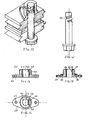
- a fastener consists of a bolt I and a socket II which connect an upper rigid plate III with a lower rigid plate IV, a resilient gasket V being interposed, generally for sealing the gap between the two rigid plates.
- the plates III and IV represent flanges of a larger body, such as for instance a container, where the socket side may be accessible or not.
- the socket II is fastened to the upper surface of the plate III by means of rivets or screws 21.
- the socket consists of a cylindrical portion 22 which is enlarged at its lower end to form an oval flange 23 perforated by holes 25 intended for its fastening by screws or rivets.
- the socket contains a throughgoing bore 24 which is provided, in its upper portion, with a protrusion in the form of a transversely and eccentrically inserted pin 26, part of which protrudes into the bore 24.
- the bolt I comprises a hexagonal nead 11 and a straight shank 12 of uniform diameter, the diameter cooperating with the bore 24 of the socket.
- the end of the shank is provided with a recess 13 which extends parallel to the shank at a depth of not less than that of the protrusion 26 into the bore, and with a helical groove 14 which merges with the recess 13 at its upper end and winds around the shank at a lead angle of not more than 10 degrees.
- the width and depth of the groove are slightly larger than the protrusion into the bore formed by the pin 26, permitting rotary motion of the bolt, while the protrusion 26 moves along the groove 14 until the resulting counter- torque prevents further turning of the bolt.
- Figure 5 illustrates a modification of the bolt I wherein a two-thread helical groove 114 starts right from the far end of the shank 112, and extends for about one third of the shank's length.
- the ground of the groove is provided with centrally located, spaced-apart knobs 115 which serve to increase the friction of the protrusion 26 with these knobs and thus to prevent slipping of the bolt out of the socket.
- the height of the knobs is such that they just contact the protrusion 26 while passing along and over it, resulting in a step-like progress of the bolt rotation, and in positive locking.
- the groove and the knobs are preferably produced by cold forming between rollers of suitable configuration or by hot forming in a die.
- the head 111 is in the shape of a wing or butterfly permitting turning of the bolt by finger action without the aid of a special tool.
- FIGs 6 and 7 illustrate a modification of the socket II.
- a protrusion 126 is formed by pressure from the outside of the cylindrical portion by means of an oblong tool, against a grooved die positioned in the bore 124 during the forming process, resulting in a transverse groove 127 on the outside of the cylindrical portion 122.
- the resulting protrusion 126 is similar to that obtained by driving a pin (26) through the cylindrical portion as illustrated in Figures 1, 3 and 4.
- the other modification shown in this figure expresses itself in the shape of the flange 123 which is circular and perforated by four holes 125.
- Figure 10 illustrates another mechanical way of producing the protrusion by positioning in the cylindrical portion 22 a pin 226 in radial direction, its inner portion protruding into the bore 24 by a length dictated by the depth of the respective helical groove in the bolt.
- FIGs '8 and 9 illustrate a socket manufactured in a die from a sintered metal or a reinforced synthetic resin.
- the cylindrical portion 122 and the flange 123 are identical with these of the socket illustrated in Figures 6 and 7, only differing in the shape and nature of the protrusion 226 which is provided with a bulbous knob 228 at the end of the semi-cylindrical protrusion 226.
- the socket is produced in a die which is necessarily provided with a divided core so as to be readily extracted from the bore.
- the fastener illustrated in Figures 11, 12, 13 and 14 differs from the foregoing in the manner of providing the protrusion in the socket. Since there exist certain difficulties in manufacturing the socket as illustrated in Figures 8 and 9 from a sintered metal or a reinforced synthetic resin in a die, the socket illustrated in these figures is assembled from two, initially separate, parts.
- the socket is recessed by a recess 40 in the shape of a swallow-tail which extends from the bore in lateral direction and from the top downwards to a short distance from the bottom of the socket.
- An insert 41 of the same or similar material and of trapezoidal cross section is tightly fitted into this recess, and contains the protrusion 42 which is inclined at the same angle as the helical groove 14 in the shank of the bolt I.
- the actual diameter of the bore is defined by two longitudinal ribs 44 which protrude out of the bore surface and form two narrow contact surfaces with the bolt I. Owing to the small areas in contact the surface pressure is increased, creating a higher friction in the contact areas and assisting in preventing the bolt from being loosened in the socket bore, even in case of vibrations.
- FIG 15 illustrates a socket 2 provided with a collar 50 which replaces the flange 23 or 123 of the aforedescribed embodiments of the socket.
- the present socket is connected to the solid body which it is to connect, with the aid of a flange 51 provided with a recess 52 cooperating with the collar 50.
- This arrangement permits a certain angular freedom of the socket and easier insertion of the bolt from underneath.
- the collar and the recess are preferably of square or hexagonal configuration, preventing rotation of the socket in the flange.
- the protrusion 42 is manufactured in the same manner as that described in respect of the socket of Figure 13.
Landscapes
- Engineering & Computer Science (AREA)
- General Engineering & Computer Science (AREA)
- Mechanical Engineering (AREA)
- Dowels (AREA)
- Connection Of Plates (AREA)
- Snaps, Bayonet Connections, Set Pins, And Snap Rings (AREA)
- Gasket Seals (AREA)
Applications Claiming Priority (2)
| Application Number | Priority Date | Filing Date | Title |
|---|---|---|---|
| IL72940A IL72940A0 (en) | 1984-09-14 | 1984-09-14 | Quick-action fastener |
| IL72940 | 1984-09-14 |
Publications (2)
| Publication Number | Publication Date |
|---|---|
| EP0178787A2 true EP0178787A2 (fr) | 1986-04-23 |
| EP0178787A3 EP0178787A3 (fr) | 1987-01-28 |
Family
ID=11055332
Family Applications (1)
| Application Number | Title | Priority Date | Filing Date |
|---|---|---|---|
| EP85306565A Withdrawn EP0178787A3 (fr) | 1984-09-14 | 1985-09-16 | Dispositif de fixation à action rapide |
Country Status (4)
| Country | Link |
|---|---|
| US (1) | US4755092A (fr) |
| EP (1) | EP0178787A3 (fr) |
| JP (1) | JPS6174908A (fr) |
| IL (1) | IL72940A0 (fr) |
Cited By (5)
| Publication number | Priority date | Publication date | Assignee | Title |
|---|---|---|---|---|
| CN106223517A (zh) * | 2016-07-15 | 2016-12-14 | 福建西河卫浴科技有限公司 | 一种连接件和使用该连接件的淋浴房及淋浴房的安装方法 |
| US11168729B2 (en) | 2019-03-12 | 2021-11-09 | Earl Allen Size, JR. | Multi-piece anti-vibration locking fastener |
| US11236778B2 (en) | 2019-03-12 | 2022-02-01 | Earl Allen Size, JR. | Multi-piece anti-vibration locking fastener having coaxially arranged inner and outer opposite threaded bolts in combination with successive and opposite threaded profiles within a thickened base layer |
| US11499583B2 (en) | 2019-03-12 | 2022-11-15 | Earl Allen Size, JR. | Fastener assembly |
| US12571420B2 (en) | 2019-03-12 | 2026-03-10 | Earl Allen Size, JR. | Multi-piece locking fastener assembly such as for securing a wheel rim to a vehicle hub |
Families Citing this family (18)
| Publication number | Priority date | Publication date | Assignee | Title |
|---|---|---|---|---|
| US5263997A (en) * | 1992-03-27 | 1993-11-23 | Westinghouse Electric Corp. | Flange bolt load spreading plate |
| US5320467A (en) * | 1993-05-20 | 1994-06-14 | General Electric Company | Positive thread start fastener |
| US5950463A (en) * | 1997-02-12 | 1999-09-14 | Glazier; James | Vehicle brake locking apparatus |
| JP2003336555A (ja) * | 2002-05-20 | 2003-11-28 | Yamaha Motor Co Ltd | クリーナエレメントの脱着構造 |
| US7661449B2 (en) * | 2003-11-10 | 2010-02-16 | Adcoriindustries, Inc. | Filling valve apparatus for a beverage filling machine |
| US20070196196A1 (en) * | 2006-02-23 | 2007-08-23 | Schorling Detlef T | High strength fastener system |
| US7955362B2 (en) * | 2006-07-21 | 2011-06-07 | Merlot Orthopedix Inc. | Apparatus and method for body tissue fixation |
| US8128330B2 (en) * | 2008-08-01 | 2012-03-06 | Varian Semiconductor Equipment Associates, Inc. | Fastening apparatus |
| US8425573B2 (en) * | 2008-10-24 | 2013-04-23 | The Cleveland Clinic Foundation | Method and system for attaching a plate to a bone |
| US8127476B2 (en) * | 2008-12-19 | 2012-03-06 | Berkeley Forge & Tool, Inc. | Quick release screw connector for earth-moving equipment |
| US8616819B1 (en) | 2011-10-06 | 2013-12-31 | Norman Koster | Lock system |
| US9433454B2 (en) | 2013-03-14 | 2016-09-06 | Amei Technologies, Inc. | Variable angle screws, plates and systems |
| JP6130443B2 (ja) * | 2015-07-21 | 2017-05-17 | サカエ理研工業株式会社 | 車両用シフトレバー装置 |
| US20180313048A1 (en) * | 2017-04-26 | 2018-11-01 | Daren Lynch | Connector for securing a snow plow blade to a supporting structure such as a moldboard |
| JP7588374B2 (ja) * | 2020-04-07 | 2024-11-22 | ニチレイマグネット株式会社 | 磁気吸着解除具、及び、それを装着した磁気吸着可能な器材又はキット |
| JP7728570B2 (ja) * | 2021-07-27 | 2025-08-25 | オプテックス株式会社 | 締結構造および該構造を備えた物体検出装置 |
| US20230258423A1 (en) * | 2022-01-14 | 2023-08-17 | Amend2, Llc | Bolt action rifle chassis |
| CN118836212A (zh) * | 2024-06-24 | 2024-10-25 | 广东罗维特金属制品有限公司 | 紧固件及其制备方法 |
Family Cites Families (24)
| Publication number | Priority date | Publication date | Assignee | Title |
|---|---|---|---|---|
| US145411A (en) * | 1873-12-09 | Improvement in screws | ||
| US890447A (en) * | 1906-04-14 | 1908-06-09 | United Shoe Machinery Ab | Fastening. |
| US1368117A (en) * | 1919-12-17 | 1921-02-08 | James C Caldwell | Clevis |
| US1782463A (en) * | 1928-09-13 | 1930-11-25 | Colantuono Mauro | Lock nut |
| US2261369A (en) * | 1940-08-13 | 1941-11-04 | Augustus M Henry | Fastener |
| US2339591A (en) * | 1942-05-22 | 1944-01-18 | Weber Nicholas | Locking device |
| US2401672A (en) * | 1942-06-29 | 1946-06-04 | Tinnerman Products Inc | Fastening device |
| US2358005A (en) * | 1942-12-24 | 1944-09-12 | Emmet M Green | Self-tightening fastener |
| US2444040A (en) * | 1943-12-18 | 1948-06-29 | Gower Marion Hutton | Detachable plate, sheet, or cowl fastening device |
| US2391761A (en) * | 1944-01-27 | 1945-12-25 | Willis E Winn | Pipe joint |
| US2396005A (en) * | 1944-10-02 | 1946-03-05 | Rohr Aircraft Corp | Sealing device |
| US2587134A (en) * | 1950-02-15 | 1952-02-26 | Tinnerman Products Inc | Combined nut retainer and thread lock |
| US2915152A (en) * | 1957-03-12 | 1959-12-01 | Thomas T Graham | Leak-proof bolt |
| NL283861A (fr) * | 1961-10-04 | |||
| GB1225507A (fr) * | 1968-07-24 | 1971-03-17 | ||
| CA849811A (en) * | 1969-01-07 | 1970-08-25 | Northern Electric Company | Spiral head adjusting screw |
| US3877341A (en) * | 1973-02-26 | 1975-04-15 | Amerace Esna Corp | Ultra-lightweight metallic threaded fasteners |
| US3958321A (en) * | 1974-06-24 | 1976-05-25 | Dzus Fastener Co., Inc. | Method of making a spring wing stud |
| FR2417665A1 (fr) * | 1978-02-20 | 1979-09-14 | Superflexit | Dispositif de liaison entre une embase et une paroi souple de reservoir |
| US4308646A (en) * | 1979-05-02 | 1982-01-05 | Dzus Fastener Co., Inc. | Front insert receptacle |
| IT1141164B (it) * | 1980-02-06 | 1986-10-01 | Seti Spa | Perno e relativa sede per collegare assime due elementi |
| US4431354A (en) * | 1981-09-03 | 1984-02-14 | Carrier Corporation | Lead screw assembly |
| EP0117217A1 (fr) * | 1983-02-18 | 1984-08-29 | Rexnord Inc. | Dispositif de fixation à commande positive bi-directionnelle du type à action rapide |
| DE3320650A1 (de) * | 1983-06-08 | 1984-12-13 | Blaupunkt-Werke Gmbh, 3200 Hildesheim | Sicherung eines auf einem zapfen drehbar gelagerten bauteils der feinmechanik |
-
1984
- 1984-09-14 IL IL72940A patent/IL72940A0/xx unknown
-
1985
- 1985-08-16 JP JP60179524A patent/JPS6174908A/ja active Pending
- 1985-09-11 US US06/775,022 patent/US4755092A/en not_active Expired - Fee Related
- 1985-09-16 EP EP85306565A patent/EP0178787A3/fr not_active Withdrawn
Cited By (5)
| Publication number | Priority date | Publication date | Assignee | Title |
|---|---|---|---|---|
| CN106223517A (zh) * | 2016-07-15 | 2016-12-14 | 福建西河卫浴科技有限公司 | 一种连接件和使用该连接件的淋浴房及淋浴房的安装方法 |
| US11168729B2 (en) | 2019-03-12 | 2021-11-09 | Earl Allen Size, JR. | Multi-piece anti-vibration locking fastener |
| US11236778B2 (en) | 2019-03-12 | 2022-02-01 | Earl Allen Size, JR. | Multi-piece anti-vibration locking fastener having coaxially arranged inner and outer opposite threaded bolts in combination with successive and opposite threaded profiles within a thickened base layer |
| US11499583B2 (en) | 2019-03-12 | 2022-11-15 | Earl Allen Size, JR. | Fastener assembly |
| US12571420B2 (en) | 2019-03-12 | 2026-03-10 | Earl Allen Size, JR. | Multi-piece locking fastener assembly such as for securing a wheel rim to a vehicle hub |
Also Published As
| Publication number | Publication date |
|---|---|
| IL72940A0 (en) | 1984-12-31 |
| US4755092A (en) | 1988-07-05 |
| EP0178787A3 (fr) | 1987-01-28 |
| JPS6174908A (ja) | 1986-04-17 |
Similar Documents
| Publication | Publication Date | Title |
|---|---|---|
| EP0178787A2 (fr) | Dispositif de fixation à action rapide | |
| US5690460A (en) | Fastener assembly for attaching a cover to a panel | |
| US5749690A (en) | Screw nut fastener assembly | |
| USRE38061E1 (en) | Method of attaching a fastening element to a panel | |
| US11828392B2 (en) | Hooked pipe coupling segment | |
| US4826376A (en) | Lock nut and method for making same | |
| US4299520A (en) | Drive nut | |
| US5791848A (en) | Structure for converting standard drive fastener to security fastener | |
| US20210088061A1 (en) | Connector Pin | |
| EP1085221A1 (fr) | Systeme de fixation | |
| US4705441A (en) | Self locking sheet metal screw | |
| US20020090277A1 (en) | Fastener with panel mounting system | |
| US5795122A (en) | Adjustable quick connect fastener for accommodating panels of various thicknesses | |
| US5340123A (en) | Pressure hardware for a modular inter-wall elastomer seal | |
| US4706437A (en) | Offset anchor | |
| US2936014A (en) | Resilient insert constricted to smaller diameter upon insertion in base member thereupon expanded to greater diameter to afford a friction lock | |
| US5209620A (en) | Fastener with differentially inclined axes | |
| US20130266395A1 (en) | Locknut with segmented ring | |
| US6109587A (en) | Manhole lift insert locator | |
| US5215206A (en) | Drum closure assembly | |
| DE7430267U (de) | Befestigungselement | |
| US3105535A (en) | Insert fastener | |
| DE202013101020U1 (de) | Vorrichtung zum Befestigen eines Trägerelements an der Karosseriestruktur eines Kraftfahrzeugs | |
| EP1054171A2 (fr) | Dispositif de fixation fileté | |
| CA1246361A (fr) | Ecrou autofreineur a pose rapide pour porte-charges |
Legal Events
| Date | Code | Title | Description |
|---|---|---|---|
| PUAI | Public reference made under article 153(3) epc to a published international application that has entered the european phase |
Free format text: ORIGINAL CODE: 0009012 |
|
| AK | Designated contracting states |
Kind code of ref document: A2 Designated state(s): AT BE CH DE FR GB IT LI SE |
|
| PUAL | Search report despatched |
Free format text: ORIGINAL CODE: 0009013 |
|
| AK | Designated contracting states |
Kind code of ref document: A3 Designated state(s): AT BE CH DE FR GB IT LI SE |
|
| 17P | Request for examination filed |
Effective date: 19870416 |
|
| 17Q | First examination report despatched |
Effective date: 19880511 |
|
| STAA | Information on the status of an ep patent application or granted ep patent |
Free format text: STATUS: THE APPLICATION IS DEEMED TO BE WITHDRAWN |
|
| 18D | Application deemed to be withdrawn |
Effective date: 19880926 |
|
| RIN1 | Information on inventor provided before grant (corrected) |
Inventor name: YANIV, ISRAEL |