EP0178848A2 - Accessoire d'éclairage à coloration dépendant de l'angle de vue - Google Patents
Accessoire d'éclairage à coloration dépendant de l'angle de vue Download PDFInfo
- Publication number
- EP0178848A2 EP0178848A2 EP85307252A EP85307252A EP0178848A2 EP 0178848 A2 EP0178848 A2 EP 0178848A2 EP 85307252 A EP85307252 A EP 85307252A EP 85307252 A EP85307252 A EP 85307252A EP 0178848 A2 EP0178848 A2 EP 0178848A2
- Authority
- EP
- European Patent Office
- Prior art keywords
- light
- sheet member
- coating
- accessory
- accessory according
- Prior art date
- Legal status (The legal status is an assumption and is not a legal conclusion. Google has not performed a legal analysis and makes no representation as to the accuracy of the status listed.)
- Withdrawn
Links
Images


Classifications
-
- F—MECHANICAL ENGINEERING; LIGHTING; HEATING; WEAPONS; BLASTING
- F21—LIGHTING
- F21V—FUNCTIONAL FEATURES OR DETAILS OF LIGHTING DEVICES OR SYSTEMS THEREOF; STRUCTURAL COMBINATIONS OF LIGHTING DEVICES WITH OTHER ARTICLES, NOT OTHERWISE PROVIDED FOR
- F21V9/00—Elements for modifying spectral properties, polarisation or intensity of the light emitted, e.g. filters
- F21V9/08—Elements for modifying spectral properties, polarisation or intensity of the light emitted, e.g. filters for producing coloured light, e.g. monochromatic; for reducing intensity of light
-
- F—MECHANICAL ENGINEERING; LIGHTING; HEATING; WEAPONS; BLASTING
- F21—LIGHTING
- F21S—NON-PORTABLE LIGHTING DEVICES; SYSTEMS THEREOF; VEHICLE LIGHTING DEVICES SPECIALLY ADAPTED FOR VEHICLE EXTERIORS
- F21S4/00—Lighting devices or systems using a string or strip of light sources
- F21S4/20—Lighting devices or systems using a string or strip of light sources with light sources held by or within elongate supports
- F21S4/28—Lighting devices or systems using a string or strip of light sources with light sources held by or within elongate supports rigid, e.g. LED bars
-
- G—PHYSICS
- G02—OPTICS
- G02B—OPTICAL ELEMENTS, SYSTEMS OR APPARATUS
- G02B5/00—Optical elements other than lenses
- G02B5/20—Filters
- G02B5/28—Interference filters
- G02B5/285—Interference filters comprising deposited thin solid films
-
- F—MECHANICAL ENGINEERING; LIGHTING; HEATING; WEAPONS; BLASTING
- F21—LIGHTING
- F21W—INDEXING SCHEME ASSOCIATED WITH SUBCLASSES F21K, F21L, F21S and F21V, RELATING TO USES OR APPLICATIONS OF LIGHTING DEVICES OR SYSTEMS
- F21W2121/00—Use or application of lighting devices or systems for decorative purposes, not provided for in codes F21W2102/00 – F21W2107/00
Definitions
- This invention relates to a viewing angle colour sensitive lighting accessory.
- Home lighting may be used for decoration, such as, for example, lighted, coloured, ceiling, wall or floor panels.
- the lighting may be solely decorative or may also be provided to light an area.
- lighting devices are provided for instructional purposes, such as, for example, lighted, coloured advertising panels or warning notices.
- the proportion and concentration of the colours on the reflector are so chosen that the reflected light has, in comparison with daylight, a greater relative proportion of the rays which are feeble in the direct light.
- the colours may be arranged upon the reflecting surface of the shade in suitable lines or patterns and the meeting edges of the different colours may be serrated.
- an optical interference authenticating means comprising a number of optical interference multilayer coatings each having spectral transmittance characteristics which vary with the angle of incidence of light thereon.
- the multilayer coatings form a covering over a transparent portion of a document to be authenticated so that the spectral transmittance characteristics may be viewed from the opposite side of the multilayer coatings, from that which the light beam impinges upon them, as a viewing angle sensitive colour change.
- a viewing angle colour sensitive, lighting accessory comprising:
- the securing means is for removably securing the sheet member to the light source.
- an electromagnetic radiation reflector securing the sheet member and extending rearwardly there behind around the light emitting source which is mounted therein, so that visible light will be reflected by the reflector forwardly towards the area from which light is to be perceived.
- each coating is normally within one or two orders of magnitude of O.lum.
- FIG. 1 there is shown a viewing angle sensitive, lighting accessory, comprising:
- the light emitting source 2 is an incandescent light fixture.
- An electromagnetic radiation reflector generally designated 5 and having a highly reflective interior, comprises an inverted U-shaped casing 8 which extends rearwardly behind the sheet member 1 so that electromagnetic radiation will be reflected by the reflector 5 forwardly towards the area from which light is to be perceived.
- the flanges 4 and 6 are attached to the sides of the inverted U-shaped casing 8 and extend inwardly therefrom.
- the reflector 5 has end walls 10 and 12.
- the light emitting source 2 is mounted in the reflector 5.
- the sheet member 1, with the multilayer coating 3 thereon, is secured on the flanges 4 and 6 by being slid on them beneath the end wall 10 until the sheet member 1 butts against the end wall 12. Thus the sheet member 1 is removably secured to the light emitting source 2.
- the light perceived from the accessory along the viewing angle of arrow A will be of a particular colouration changing to a different colouration along the viewing angle of arrow B to yet another colouration along the viewing angle C and back again through the same colourations along the viewing angles D and E. How this is achieved will be described later.
- the materials for the optical interference coatings can be selected so that the multilayer coating 3 has the property that the significant fraction of the electromagnetic radiation which is not transmitted through it is reflected back towards the highly reflective interior of the reflector 5 to be reflected back therefrom so that it has another opportunity to be transmitted through the multilayer coating.
- a light emitting source 14 comprising a light guide of the type described and claimed in United States Patent No. 4,260,220, dated April 7, 1981, " Prism Light Guide Having Surfaces which are in Octature” , L.A. Whitehead.
- the light guide comprises a longitudinal, hollow structure made of transparent or translucent material, e.g. acrylic plastic or optically clear glass, and has planar inner and outer surfaces which are in " octature” .
- An inverted U-shaped outer, protective casing 16 is provided having flanges 18 and 20 securing the sheet member 1 with the multilayer coating 3 thereon in the same manner as the flanges 4 and 6 in Figure 1.
- the light that is provided at one or both ends of the light guide may, for example, be a reflected beam of sunlight by day, when available, and an artificial beam of light at other times.
- sunlight when available, may be reflected into one end of the light guide and artificial light beamed in the other end thereof at other times.
- the lighting device shown in Figure 2 functions in the same manner as the lighting device shown in Figure 1.
- typical CIE chromaticity coordinates for the light coming directly from the sun are (.335, .340).
- typical coordinates of the blue sky are (.275, .285).
- the transmittance T and reflectance R of a non-absorbing optical interference multilayer coating 3 consisting of N layers can be expressed in terms of the refractive indices n o , n of the incident and substrate media and of the elements of the product matrix M given by
- the angle ⁇ is the angle of refraction within the j-th film. It is related to the angle of incidence 0 by Snell's law: where n j is the refractive index of the j-th layer.
- n will determine the rate at whith the coarse spectral features will shift with angle. There will be thus an optimal valme for n .
- SiO 2 is the hard coating material with the lowest refractive index (1.45), and a suitable high refractive index material is ZrO 2 which yields an acceptable refractive index ratio and mean refractive index.
- ZrO 2 which yields an acceptable refractive index ratio and mean refractive index.
- the polarization of the transmitted light increases strongly with the angle of viewing. At larger angles the transmittance for light polarized parallel to the plane of viewing is significantly larger than that for light polarized perpendicular to that plane. When the surface is mounted horizontally, this result serves to simulate the polarization characteristics of natural sky light in which peripheral rays are substantially polarized.
- the coatings were deposited onto a 0.004" thick polyester film substrate in a high vacuum box coater. An electron beam gun was used to deposit the coatings. The most sensitive wavelength method was used to monitor the deposition process. The measured normal incidence spectral transmittance of the resulting multilayer corresponded to those shown in Figure 3.
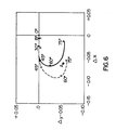
- the coated polyester film was mounted on a short section of a light guide of the type shown in Figure 2, and a portable colourimeter made by Minolta was used to measure the colour of the transmitted radiation.
- the results are shown by continuous line in Figure 6.
- the CIE coordinates of the same light guide, but without the angle sensitive lighting accessory, were measured and were found to be substantially independent of angle, as expected.
- the experimental design demonstrated that it is possible to simulate clear sky illumination with direct sunlight which is, for example, channelled through a light guide of the type shown in Figure 2, and a specially designed viewing angle sensitive, optical interference multilayer coating.
- the same design criteria can be applied to viewing angle sensitive, light accessories based on artificial light sources. For example, it is a relatively easy matter in addition to modify the normal incidence transmittance of the multilayer coating to adjust the light emissions of incandescent sources to clear sky daylight illumination.
- Lighting fixtures according to the present invention may be used for decorative effects, instructional purposes, or for a source of illumination in addition to the decorative effects or instructional purposes.
- Light fixtures according to the present invention may be used overhead, laterally spaced from or at a lower level than the observer. It is clear that for these applications many different angle sensitive, lighting accessories can be designed and constructed with other, interesting colour changes of the perceived light.
- the optical interference multilayer coating is angle sensitive with respect to polarization. It will be understood that in order for the change in polarization with angle to be observed, it is necessary for the light from the accessory to be viewed with the aid of a light polarizing device.
- the coatings of the multilayer coating 3 may be made of non-absorbing materials such as, for example, cryolite, NaF, LiF, MyF 2 , SiO 2 , ThFu, LaF,, hdF 3 , CeF,, GeO 2 , ThO 2 , Al 2 O 3 , MgO, PbF 2 , CeO 2 , Sb 2 O 3 , HfO 2 , Bi 2 O 3 , La 2 O 3 , SC 2 O 3 , Nd 2 O 3 , Ta 2 O 5 , SiN, ZrO 2 , ZnS, TiO 2 , Ag, Al, Au, Cu, Cr, Ge, Ni, NiCo, Si, Rh, or any other materials that form satisfactory layers or coatings.
- the thicknesses of the coatings will normally be within one or two orders of magnitude of 0.1 ⁇ m.
Landscapes
- Physics & Mathematics (AREA)
- Engineering & Computer Science (AREA)
- General Engineering & Computer Science (AREA)
- Spectroscopy & Molecular Physics (AREA)
- General Physics & Mathematics (AREA)
- Optics & Photonics (AREA)
- Optical Filters (AREA)
- Optical Elements Other Than Lenses (AREA)
Applications Claiming Priority (2)
| Application Number | Priority Date | Filing Date | Title |
|---|---|---|---|
| CA465387 | 1984-10-12 | ||
| CA000465387A CA1243867A (fr) | 1984-10-12 | 1984-10-12 | Accessoire d'eclairage dont la sensibilite a la couleur varie avec l'angle de visee |
Publications (2)
| Publication Number | Publication Date |
|---|---|
| EP0178848A2 true EP0178848A2 (fr) | 1986-04-23 |
| EP0178848A3 EP0178848A3 (fr) | 1989-01-04 |
Family
ID=4128914
Family Applications (1)
| Application Number | Title | Priority Date | Filing Date |
|---|---|---|---|
| EP85307252A Withdrawn EP0178848A3 (fr) | 1984-10-12 | 1985-10-10 | Accessoire d'éclairage à coloration dépendant de l'angle de vue |
Country Status (4)
| Country | Link |
|---|---|
| US (1) | US4649462A (fr) |
| EP (1) | EP0178848A3 (fr) |
| JP (1) | JPS61143719A (fr) |
| CA (1) | CA1243867A (fr) |
Cited By (1)
| Publication number | Priority date | Publication date | Assignee | Title |
|---|---|---|---|---|
| EP0605365A1 (fr) * | 1992-12-30 | 1994-07-06 | Print 2000 AG | Dispositif d'éclairage |
Families Citing this family (22)
| Publication number | Priority date | Publication date | Assignee | Title |
|---|---|---|---|---|
| JPS63147107A (ja) * | 1986-12-10 | 1988-06-20 | Matsushita Electric Ind Co Ltd | 色分離フイルタ− |
| US4973800A (en) * | 1988-12-15 | 1990-11-27 | Science Accessories Corp. | Apparatus for digitizing positions on a transparency |
| WO1990014782A1 (fr) * | 1989-06-09 | 1990-12-13 | Irv Hecker | Unites simulant des fenetres a lumiere naturelle |
| US5168646A (en) * | 1990-06-01 | 1992-12-08 | Ncm International, Inc. | Visual effect graphic and method of making same |
| US5251392A (en) * | 1991-02-08 | 1993-10-12 | Vemco Corporation | Artificial window |
| US5253051A (en) * | 1991-03-05 | 1993-10-12 | Mcmanigal Paul G | Video artificial window apparatus |
| US5207495A (en) * | 1991-07-08 | 1993-05-04 | Vemco Corporation | Graphic arts light box |
| US5303322A (en) * | 1992-03-23 | 1994-04-12 | Nioptics Corporation | Tapered multilayer luminaire devices |
| US6002829A (en) | 1992-03-23 | 1999-12-14 | Minnesota Mining And Manufacturing Company | Luminaire device |
| US5237641A (en) * | 1992-03-23 | 1993-08-17 | Nioptics Corporation | Tapered multilayer luminaire devices |
| US5528720A (en) * | 1992-03-23 | 1996-06-18 | Minnesota Mining And Manufacturing Co. | Tapered multilayer luminaire devices |
| US6313892B2 (en) | 1993-10-05 | 2001-11-06 | Teledyne Lighting And Display Products, Inc. | Light source utilizing reflective cavity having sloped side surfaces |
| CN1051379C (zh) * | 1993-10-05 | 2000-04-12 | 梯尔技术公司 | 用于背照明的光源 |
| US5440197A (en) * | 1993-10-05 | 1995-08-08 | Tir Technologies, Inc. | Backlighting apparatus for uniformly illuminating a display panel |
| US5692984A (en) * | 1994-12-09 | 1997-12-02 | Sr Engineering Company Limited | Flexible drive member for pulling and pushing and fluid-operated moving apparatus |
| US5923471A (en) * | 1996-11-26 | 1999-07-13 | Deposition Sciences, Inc. | Optical interference coating capable of withstanding severe temperature environments |
| US6473554B1 (en) | 1996-12-12 | 2002-10-29 | Teledyne Lighting And Display Products, Inc. | Lighting apparatus having low profile |
| US6007209A (en) * | 1997-03-19 | 1999-12-28 | Teledyne Industries, Inc. | Light source for backlighting |
| US6134092A (en) * | 1998-04-08 | 2000-10-17 | Teledyne Lighting And Display Products, Inc. | Illumination device for non-emissive displays |
| GB0123815D0 (en) * | 2001-10-03 | 2001-11-21 | 3M Innovative Properties Co | Light-guide lights providing a substantially monochromatic beam |
| JP4941843B2 (ja) * | 2008-02-28 | 2012-05-30 | 日本電気株式会社 | 路面標示画像処理装置、路面標示画像処理方法並びに路面標示画像処理プログラム |
| US20100103655A1 (en) * | 2008-10-29 | 2010-04-29 | Smith Andrew N | Electronic skylight system |
Family Cites Families (11)
| Publication number | Priority date | Publication date | Assignee | Title |
|---|---|---|---|---|
| CA318588A (fr) * | 1932-01-05 | Warr King Dudley | Unite d'eclairage imitant le jour | |
| CA142358A (fr) * | 1912-03-05 | 1912-08-13 | Max Weertz | Lampe |
| FR556398A (fr) * | 1922-09-20 | 1923-07-19 | Procédé et appareil pour la reconstitution artificielle de la lumière du jour | |
| US2018214A (en) * | 1933-12-05 | 1935-10-22 | Sheet Polarizer Company Inc | Advertising display device |
| FR904342A (fr) * | 1940-06-21 | 1945-11-02 | Jenaer Glaswerk Schott & Gen | Source de lumière combinée à un filtre qui laisse passer une partie des radiations émanant de la source de lumière et qui renvoie le reste de ces radiations |
| US3294964A (en) * | 1965-09-20 | 1966-12-27 | United Lighting & Ceiling Co | Polarized ceiling panel |
| CA944987A (en) * | 1972-01-18 | 1974-04-09 | National Research Council Of Canada | Optical interference authenticating means |
| US3858977A (en) * | 1972-01-18 | 1975-01-07 | Canadian Patents Dev | Optical interference authenticating means |
| US4111115A (en) * | 1977-05-23 | 1978-09-05 | Bepex Corporation | Continuous filter press |
| US4260220A (en) * | 1979-06-15 | 1981-04-07 | Canadian Patents And Development Limited | Prism light guide having surfaces which are in octature |
| GB8318224D0 (en) * | 1983-07-05 | 1983-08-03 | Britax Vega Ltd | Vehicle lamp assembly |
-
1984
- 1984-10-12 CA CA000465387A patent/CA1243867A/fr not_active Expired
-
1985
- 1985-10-10 EP EP85307252A patent/EP0178848A3/fr not_active Withdrawn
- 1985-10-11 US US06/786,696 patent/US4649462A/en not_active Expired - Lifetime
- 1985-10-11 JP JP60226622A patent/JPS61143719A/ja active Pending
Cited By (1)
| Publication number | Priority date | Publication date | Assignee | Title |
|---|---|---|---|---|
| EP0605365A1 (fr) * | 1992-12-30 | 1994-07-06 | Print 2000 AG | Dispositif d'éclairage |
Also Published As
| Publication number | Publication date |
|---|---|
| CA1243867A (fr) | 1988-11-01 |
| JPS61143719A (ja) | 1986-07-01 |
| US4649462A (en) | 1987-03-10 |
| EP0178848A3 (fr) | 1989-01-04 |
Similar Documents
| Publication | Publication Date | Title |
|---|---|---|
| US4649462A (en) | Viewing angle color sensitive lighting accessory | |
| US7192161B1 (en) | Fluorescent illumination device | |
| US5782995A (en) | Solar battery device and method of fabricating the same | |
| CA2017471A1 (fr) | Revetements de filtrage optique et lampes utilisant ces revetements | |
| US5165187A (en) | Edge illuminated sign panel | |
| US5951150A (en) | Display system | |
| AU7694196A (en) | Optically variable surface pattern | |
| EP1162059A3 (fr) | Structure colorante pour produire une coloration | |
| US4161015A (en) | Luminaire using a multilayer interference mirror | |
| KR20010034085A (ko) | 색상 변환 필름 | |
| ATE57770T1 (de) | Mit veraenderlichen optischen eigenschaften versehener duennschichtgegenstand mit einer hohen winkelabhaengigen farbenveraenderung. | |
| JPWO1995012897A1 (ja) | 太陽電池装置およびその製造方法 | |
| GB2224366A (en) | Multi-layered surface reflecting mirror | |
| US20040066654A1 (en) | Color-corrected hollow prismatic light guide luminaire | |
| CN103987519A (zh) | 用在车辆或建筑物中的复合玻璃 | |
| EP1008440A3 (fr) | Structure de revêtement | |
| IL165971A (en) | Install fluorescent lighting for lighting using fluorescent colors | |
| CA2087589A1 (fr) | Verre decoratif | |
| JPH0476228B2 (fr) | ||
| GB2191415A (en) | A light display device e.g. for creating rainbows | |
| US5359498A (en) | Ultraviolet transmitting multi-layer polarizer | |
| WO2012101393A1 (fr) | Structure de surface ayant des propriétés de réflectance et de transmission de la lumière, et son procédé de fabrication | |
| WO2004079278A1 (fr) | Vitrage | |
| JP3911046B2 (ja) | 波長選択性を有する光学部材 | |
| EP0402075A3 (fr) | Verre absorbant les rayons thermiques |
Legal Events
| Date | Code | Title | Description |
|---|---|---|---|
| PUAI | Public reference made under article 153(3) epc to a published international application that has entered the european phase |
Free format text: ORIGINAL CODE: 0009012 |
|
| AK | Designated contracting states |
Kind code of ref document: A2 Designated state(s): DE FR GB IT |
|
| RIN1 | Information on inventor provided before grant (corrected) |
Inventor name: WHITEHEAD, LORNE A. Inventor name: DOBROWOLSKI, JERZY A. |
|
| PUAL | Search report despatched |
Free format text: ORIGINAL CODE: 0009013 |
|
| AK | Designated contracting states |
Kind code of ref document: A3 Designated state(s): DE FR GB IT |
|
| STAA | Information on the status of an ep patent application or granted ep patent |
Free format text: STATUS: THE APPLICATION IS DEEMED TO BE WITHDRAWN |
|
| 18D | Application deemed to be withdrawn |
Effective date: 19890605 |
|
| RIN1 | Information on inventor provided before grant (corrected) |
Inventor name: DOBROWOLSKI, JERZY A. Inventor name: WHITEHEAD, LORNE A. |