EP0178933A2 - Autokorrelationsfilter - Google Patents
Autokorrelationsfilter Download PDFInfo
- Publication number
- EP0178933A2 EP0178933A2 EP85307504A EP85307504A EP0178933A2 EP 0178933 A2 EP0178933 A2 EP 0178933A2 EP 85307504 A EP85307504 A EP 85307504A EP 85307504 A EP85307504 A EP 85307504A EP 0178933 A2 EP0178933 A2 EP 0178933A2
- Authority
- EP
- European Patent Office
- Prior art keywords
- auto
- filter
- correlation function
- power
- frame
- Prior art date
- Legal status (The legal status is an assumption and is not a legal conclusion. Google has not performed a legal analysis and makes no representation as to the accuracy of the status listed.)
- Granted
Links
- 238000005311 autocorrelation function Methods 0.000 claims abstract description 43
- 230000008878 coupling Effects 0.000 claims description 26
- 238000010168 coupling process Methods 0.000 claims description 26
- 238000005859 coupling reaction Methods 0.000 claims description 26
- 238000004364 calculation method Methods 0.000 claims description 25
- 230000009466 transformation Effects 0.000 claims description 12
- 238000000034 method Methods 0.000 claims description 5
- 238000005070 sampling Methods 0.000 description 8
- 230000006870 function Effects 0.000 description 6
- 238000010276 construction Methods 0.000 description 4
- 238000013461 design Methods 0.000 description 4
- 238000010586 diagram Methods 0.000 description 3
- 238000010183 spectrum analysis Methods 0.000 description 3
- 238000007792 addition Methods 0.000 description 2
- 230000000903 blocking effect Effects 0.000 description 2
- 238000012546 transfer Methods 0.000 description 2
- 238000001514 detection method Methods 0.000 description 1
- 238000012986 modification Methods 0.000 description 1
- 230000004048 modification Effects 0.000 description 1
- 238000012545 processing Methods 0.000 description 1
- 230000000717 retained effect Effects 0.000 description 1
- 238000001228 spectrum Methods 0.000 description 1
Images


Classifications
-
- H—ELECTRICITY
- H03—ELECTRONIC CIRCUITRY
- H03H—IMPEDANCE NETWORKS, e.g. RESONANT CIRCUITS; RESONATORS
- H03H17/00—Networks using digital techniques
- H03H17/02—Frequency selective networks
Definitions
- the present invention relates to a filter for outputting the power of a signal passing through a specified frequency band for each frame (short time division).
- FFT fast fourier transform
- digital filter In spectrum analysis and sound identification, FFT (fast fourier transform) and digital filter are two typical means for obtaining the power of a signal of a particular frequency band through digital processing.
- Method with FFT is as follows. First, a signal waveform is subjected to FFT to calculate the power of each frequency component. Then, the powers of the frequency components corresponding to the passing band of the filter are multiplied by the frequency characteristic of the filter and summed up, so that the power for each frame is obtained.
- This method is advantageous in that a filter of a desired characteristic is easily realized. The problem is, however, that FFT involves many. calculation stages.
- Method with a digital filter is as follows. After a signal is passed through a specified filter, the square-law detection is conducted on the waveform. Then, the signal is passed through a low-pass-filter to sample the power for each frame.
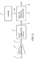
- an analog signal 101 is converted by an analog/digital converter 102 to a digital signal 103 which is passed through a digital filter 104 with a specified frequency characteristic so as to obtain a signal 105 having the passing band frequency component.
- the signal 105 is passed through a square-law detector 106 to square the signal value, thus obtaining an instantaneous power signal 107.
- the signal 107 is then passed through an anti-alias low-pass-filter 108 to obtain a reflected noise-free signal 109 which is sampled by a sampling circuit 110 at frame intervals to obtain output power 111.
- an.object of the present invention is to provide a novel auto-correlation filter which requires minimum calculation stages.
- Another object of the present invention is to provide a filter for calculating the power of a specified frequency band for each frame, the filter effectively realizing an auto-correlation filter by minimum calculation stages and auto-correlation function.
- a filter includes means for outputting the power of a signal passing through a specified frequency band for each frame (short time division), means for calculating auto-correlation function of the input signal, and means for obtaining the power as the linear-coupled auto-correlation function of the frame, using the calculated auto-correlation function.
- N is the number of sampling points in one frame
- L' being the number of channels to be realized, with the assumption that the degree of auto-correlation function is from 0 to M:
- the filter whose calculation mainly consists of sum of products is suitable to a digital single processor that is quick in the sum-of-products calculation.
- the output power P F of the filter is the linear coupled auto-correlation function ⁇ (t).
- a(t) is a cosine transformation of F (k).
- the linear coupling coefficient aw(t) can be calculated by the equation:
- the filter frequency characteristic Fw(k) multiplied by the window function is obtained by using aw(t) in place of a(t) in the equation (9). * Refer to the equation (10). * Refer to the equations (8) and (11).
- Fw(k) is expressed as a convolution of the original frequency characteristic F(k) and W(k).
- the filter of the present invention is very convenient in realizing a filter bank used for spectrum analysis and sound identification, that is, a multichannel band-pass-filter.
- a filter bank used for spectrum analysis and sound identification that is, a multichannel band-pass-filter.
- many channels the filter may have calculation is needed only once to the specified degree of the auto-correlation function. Calculation for the linear coupling must be conducted for each channel, but the number of the calculation stages is small.
- the memory for storing coefficients need not have a large capacity.
- the filter of the present invention does not contain a feedback loop, and therefore does not present a problem such as limit cycle.
- the filter to be designed has a sampling frequency of lOkHz, 200 sampling points for a frame, and a passing band of 2,200 ⁇ 2,600Hz.
- An ideal filter must have such characteristics that the attenuation in the passing band is OdB and that in the blocking band is -100dB.
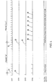
- Fig. 5 shows the linear coupling coefficient for the ideal filter characteristics, calculated by the cosine transformation of the equation (8).
- the coefficient is symmetrical with respect to the 100 sample time.
- the auto- correlation function itself is also symmetrical. Therefore, sum-of-products calculation is needed only up to the 100 sample time; division by 2 is not necessary.
- Fig. 6 shows the weighted coefficient of the equation (10), with the value for the auto-correlation function up to the 25 sample time being restricted by a rectangular window.
- the cosine transformation of the rectangular window is shown in Fig. 7.
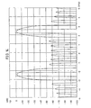
- Calculation of the convolution equation (14) for the cosine transformation of the rectangular window and the ideal filter frequency characteristic yields the frequency characteristic multiplied by the rectangular window as shown in Fig. 8.
- This frequency characteristic with a large (-30dB) side lobe can be improved by raising the degree of the auto-correlation function.
- the thick lines indicate an ideal band-pass-filter.
- the linear coupling coefficient of the auto-correlation function restricted by a Hanning window instead of the rectangular window, the cosine transformation of the Hanning window and the frequency characteristic are shown in Figs. 9, 10 and 11, respectively.
- the linear coupling coefficient of the auto-correlation function restricted by a Hamming window, the cosine transformation of the Hamming window and the frequency characteristic are shown in Figs. 12, 13 and 14, respectively.
- Figs. 11 and 14 have very small side lobes (-55dB) but present very wide passing bands.
- it is necessary to select a suitable degree for the auto- correlation function and an appropriate window function according to the purpose.
- the degree of the auto-correlation function for the filter of the present invention is assumed to be 0 to 9.
- Fig. 2 shows the entire construction of a filter of the present invention.
- An analog signal input from an input terminal 1 is converted to a digital signal 3 by an analog/digital converter 2.
- the digital signal 3 enters an auto-correlation circuit 4 where the auto-correlation function is calculated for each frame and outputted.
- the auto-correlation function 5 enters a sum-of-products calculator 6 where it is multiplied by a linear coupling coefficient 8 read from a memory 7 and the products are summed up as indicated by the equation (7). The sum is outputted as the power 9 of the filter.
- the memory 7 has stored coefficients for plural kinds of auto-correlation filters, outputs of a plurality of auto-correlation filters are easily obtained by conducting sum-of-products calculation for the auto-correlation functions and the coefficients sequentially read from the memory 7.
- the circuit of the auto-correlation filter and the operation timing will be described in detail with reference to Figs. 3 and 4.
- the memory 7 stores auto-correlation filter coefficients for 8 channels.
- analog signal inputs 1 are converted by an A/D converter 2 to digital signals 3 which are stored in a shift register 41 in turn.
- the shift register 41 and the A/D converter 2 are operated synchronously with a sampling clock signal CK1 which is continually supplied at a constant interval as shown in Fig. 4.
- Frames are set for calculating the power of the auto-correlation filter.
- the number of sampling points for one frame is N in the equation (5).
- the "m"th frame comprises the sampling pulses from to @.
- the last data "a” and an appropriate data "b” ⁇ "j" for each stage are transmitted to respective multipliers 42a ⁇ 42j where the auto-correlation function is calculated.
- the last data "a” of the shift register 41 is squared.
- the last data "a” is multiplied by the last but one data "b”.
- auto-correlation functions of up to the 9th degree are calculated by multiplying the last data "a” and the data "c” ⁇ "j” for the respective stages in turn.
- the data outputs from the multipliers 42a ⁇ 42j are supplied to the corresponding adders 43a-.43j to obtain the sum for one frame.
- the partial sum registers 44a ⁇ 44j transfer the auto- correlation functions to the following auto-correlation registers 45a ⁇ 45j by the pulse of the clock signal CK3, so that the partial sum registers 44a ⁇ 44j are available for calculation for the next frame. After this data transfer, the partial sum registers 44a ⁇ 44j are cleared by the pulse of the clock signal CK2 to be available for retaining the partial sums for the next frame.
- an address register 71 of the memory 72 is initialized for the address that stores the linear coupling coefficients a l (t) of the No. 1 channel by the pulse 4 of the clock signal CK3.
- the memory 72 outputs linear coupling coefficients a l (O), al(l), ... a l (9) of the No. 1 channel, the values being set in the respective areas of a memory register 73 by the pulse 10 of the clock signal CK4.
- the address register 71 is counted up by one by the pulse 10 of the clock signal CK4 so as to designate the address storing the linear coupling coefficients a z (t) of the No. 2 channel.
- the pulses 11 ⁇ 16of the clock signal CK4 linear coupling coefficients of the subsequent channels are read from the memory 72 and set in the memory register 73 in turn.
- the auto-correlation functions preliminarily calculated and retained in the auto-correlation registers 45a ⁇ 45j are multiplied by the corresponding linear coupling coefficients set in the memory register 73 in respective multipliers 61a ⁇ 61j.
- the multiplier 61a multiplies the auto-correlation function of the Oth degree stored in the auto-correlation register 45a and the linear coupling coefficient a i (0) stored in the area "ma" of the memory register 73.
- the auto-correlation functions of the 1st to the 9th degree are sequentially multiplied by al(l) ..., and a 1 (9) in the multipliers 61a ⁇ 61j, and the products are outputted.
- the product outputs are summed up by adders 62 ⁇ 69 and 60, and the total sum is outputted from an output terminal 91 as a filter output.
- the output terminal 91 outputs power CH1 of the No. 1 channel of the filter at first.
- Powers CH2 ⁇ CH8 of the No. 2 ⁇ No. 8 channels of the filter are outputted in turn as linear coupling coefficients for these channels are set in the memory registers by the clock pulses 10 ⁇ 16 of the clock signal CK4.
Landscapes
- Physics & Mathematics (AREA)
- Engineering & Computer Science (AREA)
- Computer Hardware Design (AREA)
- Mathematical Physics (AREA)
- Complex Calculations (AREA)
Applications Claiming Priority (2)
| Application Number | Priority Date | Filing Date | Title |
|---|---|---|---|
| JP219240/84 | 1984-10-17 | ||
| JP59219240A JPS6196817A (ja) | 1984-10-17 | 1984-10-17 | フイルタ− |
Publications (3)
| Publication Number | Publication Date |
|---|---|
| EP0178933A2 true EP0178933A2 (de) | 1986-04-23 |
| EP0178933A3 EP0178933A3 (en) | 1987-09-16 |
| EP0178933B1 EP0178933B1 (de) | 1993-06-09 |
Family
ID=16732406
Family Applications (1)
| Application Number | Title | Priority Date | Filing Date |
|---|---|---|---|
| EP85307504A Expired - Lifetime EP0178933B1 (de) | 1984-10-17 | 1985-10-17 | Autokorrelationsfilter |
Country Status (4)
| Country | Link |
|---|---|
| US (1) | US4766563A (de) |
| EP (1) | EP0178933B1 (de) |
| JP (1) | JPS6196817A (de) |
| DE (1) | DE3587393T2 (de) |
Cited By (1)
| Publication number | Priority date | Publication date | Assignee | Title |
|---|---|---|---|---|
| WO1989008910A1 (en) * | 1988-03-11 | 1989-09-21 | British Telecommunications Public Limited Company | Voice activity detection |
Families Citing this family (17)
| Publication number | Priority date | Publication date | Assignee | Title |
|---|---|---|---|---|
| JPS63198131A (ja) * | 1987-02-04 | 1988-08-16 | テキサス インスツルメンツ インコーポレイテツド | ディジタル形計算相関マトリクスと入力データを処理する方法 |
| US4860239A (en) * | 1987-08-12 | 1989-08-22 | Unisys Corporation | Correlator with variably normalized input signals |
| US5130942A (en) * | 1988-02-24 | 1992-07-14 | Canon Kabushiki Kaisha | Digital filter with front stage division |
| IT1227520B (it) * | 1988-12-06 | 1991-04-12 | Sgs Thomson Microelectronics | Filtro digitale programmabile |
| JPH05505282A (ja) * | 1989-07-25 | 1993-08-05 | セイコー株式会社 | デジタル・フィルターとその設計方法 |
| JP2975041B2 (ja) * | 1990-03-27 | 1999-11-10 | 株式会社日立製作所 | ディジタル信号処理プロセッサ |
| US5349546A (en) * | 1992-06-01 | 1994-09-20 | Eastman Kodak Company | Method and apparatus for non-linear signal processing with reduced upper harmonic components |
| US5502664A (en) * | 1993-03-25 | 1996-03-26 | Yozan Inc. | Filter device including SRAM and EEPROM devices |
| US5500810A (en) * | 1993-04-28 | 1996-03-19 | Yozan Inc. | Filter device with memory test circuit |
| US5390244A (en) * | 1993-09-10 | 1995-02-14 | Polycom, Inc. | Method and apparatus for periodic signal detection |
| US5851679A (en) * | 1996-12-17 | 1998-12-22 | General Electric Company | Multilayer dielectric stack coated part for contact with combustion gases |
| US6191853B1 (en) * | 1998-09-29 | 2001-02-20 | Horiba, Ltd. | Apparatus for measuring particle size distribution and method for analyzing particle size distribution |
| JP2003168958A (ja) * | 2001-11-29 | 2003-06-13 | Sakai Yasue | デジタルフィルタの設計方法および設計装置、デジタルフィルタ設計用プログラム、デジタルフィルタ |
| WO2003096534A1 (en) * | 2002-05-09 | 2003-11-20 | Neuro Solution Corp. | Tone quality adjustment device designing method and designing device, tone quality adjustment device designing program, and tone quality adjustment device |
| US7400676B2 (en) | 2002-05-09 | 2008-07-15 | Neuro Solution Corp. | Tone quality adjustment device designing method and designing device, tone quality adjustment device designing program, and tone quality adjustment device |
| US20030235243A1 (en) * | 2002-06-25 | 2003-12-25 | Shousheng He | Method for windowed noise auto-correlation |
| US9927783B2 (en) | 2014-09-15 | 2018-03-27 | Emerson Electric Co. | Analog signal processing using a correlator digital filter |
Family Cites Families (2)
| Publication number | Priority date | Publication date | Assignee | Title |
|---|---|---|---|---|
| CA1068409A (en) * | 1975-12-12 | 1979-12-18 | Pierre-Andre Grandchamp | Determination of parameters of an autocorrelation function |
| US4404645A (en) * | 1980-08-18 | 1983-09-13 | Elings Virgil B | Correlator |
-
1984
- 1984-10-17 JP JP59219240A patent/JPS6196817A/ja active Granted
-
1985
- 1985-10-08 US US06/785,515 patent/US4766563A/en not_active Expired - Lifetime
- 1985-10-17 EP EP85307504A patent/EP0178933B1/de not_active Expired - Lifetime
- 1985-10-17 DE DE8585307504T patent/DE3587393T2/de not_active Expired - Fee Related
Non-Patent Citations (1)
| Title |
|---|
| IEEE TRANSACTIONS ON INDUSTRIAL ELECTRONICS, vol. IE-29, no. 1, February 1982, pages 73-82, IEEE, New York, US; S. GANESAN et al.: "A real-time digital signal analyser correlator average power spectral density analyzer" * |
Cited By (2)
| Publication number | Priority date | Publication date | Assignee | Title |
|---|---|---|---|---|
| WO1989008910A1 (en) * | 1988-03-11 | 1989-09-21 | British Telecommunications Public Limited Company | Voice activity detection |
| EP0335521A1 (de) * | 1988-03-11 | 1989-10-04 | BRITISH TELECOMMUNICATIONS public limited company | Detektion für die Anwesenheit eines Sprachsignals |
Also Published As
| Publication number | Publication date |
|---|---|
| JPH036689B2 (de) | 1991-01-30 |
| DE3587393T2 (de) | 1993-09-16 |
| DE3587393D1 (de) | 1993-07-15 |
| JPS6196817A (ja) | 1986-05-15 |
| US4766563A (en) | 1988-08-23 |
| EP0178933B1 (de) | 1993-06-09 |
| EP0178933A3 (en) | 1987-09-16 |
Similar Documents
| Publication | Publication Date | Title |
|---|---|---|
| EP0178933A2 (de) | Autokorrelationsfilter | |
| EP0649578B1 (de) | Digitales filter mit hoher genauigkeit und effizienz | |
| US5150413A (en) | Extraction of phonemic information | |
| Bluestein | A linear filtering approach to the computation of discrete Fourier transform | |
| Helms | Nonrecursive digital filters: Design methods for achieving specifications on frequency response | |
| US4723125A (en) | Device for calculating a discrete moving window transform and application thereof to a radar system | |
| US5070337A (en) | Optimization method and an optimized filter for sidelobe suppression | |
| US4340781A (en) | Speech analysing device | |
| US4791597A (en) | Multiplierless FIR digital filter with two to the Nth power coefficients | |
| US4282579A (en) | Discrete Fourier transform system using the dual chirp-Z transform | |
| EP0015681A1 (de) | Binäres Transversalfilter | |
| US4992967A (en) | Digital filter using fourier transformation | |
| US4852034A (en) | Digital filter | |
| GB2332998A (en) | Digital Doppler signal processing for radar | |
| US4744042A (en) | Transform processor system having post processing | |
| US5928314A (en) | Digital filter having a substantially equal number of negative and positive weighting factors | |
| US8615538B1 (en) | Sub-filtering finite impulse response (FIR) filter for frequency search capability | |
| US5901075A (en) | Performance of an adaptive weight FIR filter having a timeshared tap weight processor | |
| US5179529A (en) | High speed fourier transform engine | |
| US5168456A (en) | Incremental frequency domain correlator | |
| US8340285B2 (en) | Method for efficient and zero latency filtering in a long impulse response system | |
| KR100193385B1 (ko) | 단일화된 시스톨릭어레이 구조에 의한 dct/dst/dht의 수행 방법 및 그 장치 | |
| JP2622962B2 (ja) | Fftアナライザのズーミング装置 | |
| JP2558846B2 (ja) | デジタルフィルタバンク | |
| Peterson et al. | The multichannel spectrum analyzer |
Legal Events
| Date | Code | Title | Description |
|---|---|---|---|
| PUAI | Public reference made under article 153(3) epc to a published international application that has entered the european phase |
Free format text: ORIGINAL CODE: 0009012 |
|
| AK | Designated contracting states |
Kind code of ref document: A2 Designated state(s): DE FR GB |
|
| PUAL | Search report despatched |
Free format text: ORIGINAL CODE: 0009013 |
|
| AK | Designated contracting states |
Kind code of ref document: A3 Designated state(s): DE FR GB |
|
| 17P | Request for examination filed |
Effective date: 19880302 |
|
| 17Q | First examination report despatched |
Effective date: 19891130 |
|
| GRAA | (expected) grant |
Free format text: ORIGINAL CODE: 0009210 |
|
| AK | Designated contracting states |
Kind code of ref document: B1 Designated state(s): DE FR GB |
|
| REF | Corresponds to: |
Ref document number: 3587393 Country of ref document: DE Date of ref document: 19930715 |
|
| ET | Fr: translation filed | ||
| PLBE | No opposition filed within time limit |
Free format text: ORIGINAL CODE: 0009261 |
|
| STAA | Information on the status of an ep patent application or granted ep patent |
Free format text: STATUS: NO OPPOSITION FILED WITHIN TIME LIMIT |
|
| 26N | No opposition filed | ||
| REG | Reference to a national code |
Ref country code: GB Ref legal event code: IF02 |
|
| PGFP | Annual fee paid to national office [announced via postgrant information from national office to epo] |
Ref country code: FR Payment date: 20021008 Year of fee payment: 18 |
|
| PGFP | Annual fee paid to national office [announced via postgrant information from national office to epo] |
Ref country code: GB Payment date: 20021016 Year of fee payment: 18 |
|
| PGFP | Annual fee paid to national office [announced via postgrant information from national office to epo] |
Ref country code: DE Payment date: 20021017 Year of fee payment: 18 |
|
| PG25 | Lapsed in a contracting state [announced via postgrant information from national office to epo] |
Ref country code: GB Free format text: LAPSE BECAUSE OF NON-PAYMENT OF DUE FEES Effective date: 20031017 |
|
| PG25 | Lapsed in a contracting state [announced via postgrant information from national office to epo] |
Ref country code: DE Free format text: LAPSE BECAUSE OF NON-PAYMENT OF DUE FEES Effective date: 20040501 |
|
| GBPC | Gb: european patent ceased through non-payment of renewal fee |
Effective date: 20031017 |
|
| PG25 | Lapsed in a contracting state [announced via postgrant information from national office to epo] |
Ref country code: FR Free format text: LAPSE BECAUSE OF NON-PAYMENT OF DUE FEES Effective date: 20040630 |
|
| REG | Reference to a national code |
Ref country code: FR Ref legal event code: ST |