EP0179247A1 - Dispositif de conversion des informations d'une image de rayonnement enregistrée sur une cible en une suite de signaux de télévision - Google Patents
Dispositif de conversion des informations d'une image de rayonnement enregistrée sur une cible en une suite de signaux de télévision Download PDFInfo
- Publication number
- EP0179247A1 EP0179247A1 EP85111422A EP85111422A EP0179247A1 EP 0179247 A1 EP0179247 A1 EP 0179247A1 EP 85111422 A EP85111422 A EP 85111422A EP 85111422 A EP85111422 A EP 85111422A EP 0179247 A1 EP0179247 A1 EP 0179247A1
- Authority
- EP
- European Patent Office
- Prior art keywords
- light
- light guide
- drum
- scanning
- storage layer
- Prior art date
- Legal status (The legal status is an assumption and is not a legal conclusion. Google has not performed a legal analysis and makes no representation as to the accuracy of the status listed.)
- Granted
Links
- 230000005855 radiation Effects 0.000 title claims abstract description 9
- 108010076504 Protein Sorting Signals Proteins 0.000 title claims description 8
- 230000003287 optical effect Effects 0.000 claims abstract description 5
- VYPSYNLAJGMNEJ-UHFFFAOYSA-N silicon dioxide Inorganic materials O=[Si]=O VYPSYNLAJGMNEJ-UHFFFAOYSA-N 0.000 claims description 10
- 238000006073 displacement reaction Methods 0.000 claims description 3
- 239000010453 quartz Substances 0.000 claims description 2
- 238000006243 chemical reaction Methods 0.000 abstract description 4
- 238000001208 nuclear magnetic resonance pulse sequence Methods 0.000 abstract 1
- 239000010410 layer Substances 0.000 description 19
- OAICVXFJPJFONN-UHFFFAOYSA-N Phosphorus Chemical compound [P] OAICVXFJPJFONN-UHFFFAOYSA-N 0.000 description 12
- 238000012546 transfer Methods 0.000 description 9
- 230000001960 triggered effect Effects 0.000 description 9
- 230000005540 biological transmission Effects 0.000 description 7
- 239000011521 glass Substances 0.000 description 7
- VVQNEPGJFQJSBK-UHFFFAOYSA-N Methyl methacrylate Chemical compound COC(=O)C(C)=C VVQNEPGJFQJSBK-UHFFFAOYSA-N 0.000 description 4
- 229920005372 Plexiglas® Polymers 0.000 description 4
- 201000009310 astigmatism Diseases 0.000 description 4
- 239000000126 substance Substances 0.000 description 4
- 239000004020 conductor Substances 0.000 description 3
- 238000012937 correction Methods 0.000 description 3
- 230000008878 coupling Effects 0.000 description 3
- 238000010168 coupling process Methods 0.000 description 3
- 238000005859 coupling reaction Methods 0.000 description 3
- CPBQJMYROZQQJC-UHFFFAOYSA-N helium neon Chemical compound [He].[Ne] CPBQJMYROZQQJC-UHFFFAOYSA-N 0.000 description 3
- 239000013307 optical fiber Substances 0.000 description 3
- 238000012545 processing Methods 0.000 description 3
- 238000001228 spectrum Methods 0.000 description 3
- 239000012780 transparent material Substances 0.000 description 3
- 229910020314 ClBr Inorganic materials 0.000 description 2
- GWEVSGVZZGPLCZ-UHFFFAOYSA-N Titan oxide Chemical compound O=[Ti]=O GWEVSGVZZGPLCZ-UHFFFAOYSA-N 0.000 description 2
- 238000005253 cladding Methods 0.000 description 2
- 230000007423 decrease Effects 0.000 description 2
- 238000013461 design Methods 0.000 description 2
- 230000000694 effects Effects 0.000 description 2
- 239000000835 fiber Substances 0.000 description 2
- 239000000463 material Substances 0.000 description 2
- 238000000034 method Methods 0.000 description 2
- 238000009304 pastoral farming Methods 0.000 description 2
- 229920003229 poly(methyl methacrylate) Polymers 0.000 description 2
- 239000004926 polymethyl methacrylate Substances 0.000 description 2
- 229910052693 Europium Inorganic materials 0.000 description 1
- XAGFODPZIPBFFR-UHFFFAOYSA-N aluminium Chemical compound [Al] XAGFODPZIPBFFR-UHFFFAOYSA-N 0.000 description 1
- 229910052782 aluminium Inorganic materials 0.000 description 1
- 229910052788 barium Inorganic materials 0.000 description 1
- DSAJWYNOEDNPEQ-UHFFFAOYSA-N barium atom Chemical compound [Ba] DSAJWYNOEDNPEQ-UHFFFAOYSA-N 0.000 description 1
- 239000004568 cement Substances 0.000 description 1
- 239000003795 chemical substances by application Substances 0.000 description 1
- 239000011248 coating agent Substances 0.000 description 1
- 238000000576 coating method Methods 0.000 description 1
- 230000001627 detrimental effect Effects 0.000 description 1
- 238000011161 development Methods 0.000 description 1
- 230000018109 developmental process Effects 0.000 description 1
- 238000004090 dissolution Methods 0.000 description 1
- 239000000428 dust Substances 0.000 description 1
- 239000003822 epoxy resin Substances 0.000 description 1
- OGPBJKLSAFTDLK-UHFFFAOYSA-N europium atom Chemical compound [Eu] OGPBJKLSAFTDLK-UHFFFAOYSA-N 0.000 description 1
- 230000002349 favourable effect Effects 0.000 description 1
- 238000005286 illumination Methods 0.000 description 1
- 238000003384 imaging method Methods 0.000 description 1
- 210000004072 lung Anatomy 0.000 description 1
- 230000000149 penetrating effect Effects 0.000 description 1
- 229920003023 plastic Polymers 0.000 description 1
- 239000004033 plastic Substances 0.000 description 1
- 229920000647 polyepoxide Polymers 0.000 description 1
- 239000011241 protective layer Substances 0.000 description 1
- 239000004065 semiconductor Substances 0.000 description 1
- 239000007787 solid Substances 0.000 description 1
- 230000003595 spectral effect Effects 0.000 description 1
- 239000011232 storage material Substances 0.000 description 1
- 239000004408 titanium dioxide Substances 0.000 description 1
- OGIDPMRJRNCKJF-UHFFFAOYSA-N titanium oxide Inorganic materials [Ti]=O OGIDPMRJRNCKJF-UHFFFAOYSA-N 0.000 description 1
- 238000002834 transmittance Methods 0.000 description 1
- 238000011144 upstream manufacturing Methods 0.000 description 1
Images



Classifications
-
- G—PHYSICS
- G03—PHOTOGRAPHY; CINEMATOGRAPHY; ANALOGOUS TECHNIQUES USING WAVES OTHER THAN OPTICAL WAVES; ELECTROGRAPHY; HOLOGRAPHY
- G03B—APPARATUS OR ARRANGEMENTS FOR TAKING PHOTOGRAPHS OR FOR PROJECTING OR VIEWING THEM; APPARATUS OR ARRANGEMENTS EMPLOYING ANALOGOUS TECHNIQUES USING WAVES OTHER THAN OPTICAL WAVES; ACCESSORIES THEREFOR
- G03B42/00—Obtaining records using waves other than optical waves; Visualisation of such records by using optical means
- G03B42/08—Visualisation of records by optical means
-
- H—ELECTRICITY
- H04—ELECTRIC COMMUNICATION TECHNIQUE
- H04N—PICTORIAL COMMUNICATION, e.g. TELEVISION
- H04N1/00—Scanning, transmission or reproduction of documents or the like, e.g. facsimile transmission; Details thereof
- H04N1/024—Details of scanning heads ; Means for illuminating the original
- H04N1/028—Details of scanning heads ; Means for illuminating the original for picture information pick-up
- H04N1/0281—Details of scanning heads ; Means for illuminating the original for picture information pick-up with means for collecting light from a line or an area of the original and for guiding it to only one or a relatively low number of picture element detectors
-
- H—ELECTRICITY
- H04—ELECTRIC COMMUNICATION TECHNIQUE
- H04N—PICTORIAL COMMUNICATION, e.g. TELEVISION
- H04N1/00—Scanning, transmission or reproduction of documents or the like, e.g. facsimile transmission; Details thereof
- H04N1/04—Scanning arrangements, i.e. arrangements for the displacement of active reading or reproducing elements relative to the original or reproducing medium, or vice versa
- H04N1/06—Scanning arrangements, i.e. arrangements for the displacement of active reading or reproducing elements relative to the original or reproducing medium, or vice versa using cylindrical picture-bearing surfaces, i.e. scanning a main-scanning line substantially perpendicular to the axis and lying in a curved cylindrical surface
- H04N1/0607—Scanning a concave surface, e.g. with internal drum type scanners
- H04N1/0621—Scanning a concave surface, e.g. with internal drum type scanners using a picture-bearing surface stationary in the main-scanning direction
- H04N1/0635—Scanning a concave surface, e.g. with internal drum type scanners using a picture-bearing surface stationary in the main-scanning direction using oscillating or rotating mirrors
-
- H—ELECTRICITY
- H04—ELECTRIC COMMUNICATION TECHNIQUE
- H04N—PICTORIAL COMMUNICATION, e.g. TELEVISION
- H04N1/00—Scanning, transmission or reproduction of documents or the like, e.g. facsimile transmission; Details thereof
- H04N1/04—Scanning arrangements, i.e. arrangements for the displacement of active reading or reproducing elements relative to the original or reproducing medium, or vice versa
- H04N1/06—Scanning arrangements, i.e. arrangements for the displacement of active reading or reproducing elements relative to the original or reproducing medium, or vice versa using cylindrical picture-bearing surfaces, i.e. scanning a main-scanning line substantially perpendicular to the axis and lying in a curved cylindrical surface
- H04N1/0657—Scanning a transparent surface, e.g. reading a transparency original
-
- H—ELECTRICITY
- H04—ELECTRIC COMMUNICATION TECHNIQUE
- H04N—PICTORIAL COMMUNICATION, e.g. TELEVISION
- H04N1/00—Scanning, transmission or reproduction of documents or the like, e.g. facsimile transmission; Details thereof
- H04N1/04—Scanning arrangements, i.e. arrangements for the displacement of active reading or reproducing elements relative to the original or reproducing medium, or vice versa
- H04N1/06—Scanning arrangements, i.e. arrangements for the displacement of active reading or reproducing elements relative to the original or reproducing medium, or vice versa using cylindrical picture-bearing surfaces, i.e. scanning a main-scanning line substantially perpendicular to the axis and lying in a curved cylindrical surface
- H04N1/0664—Scanning arrangements, i.e. arrangements for the displacement of active reading or reproducing elements relative to the original or reproducing medium, or vice versa using cylindrical picture-bearing surfaces, i.e. scanning a main-scanning line substantially perpendicular to the axis and lying in a curved cylindrical surface with sub-scanning by translational movement of the picture-bearing surface
Definitions
- the invention relates to a device for converting the radiation image information carried by a storage layer into a television signal sequence according to the preamble of claim 1.
- Such devices are known, for example, from US Pat. No. 3,859,527.
- Some of the light generated by the X-rays is stored, for example when X-ray images are recorded in layers which contain a storage phosphor, ie a phosphorescent substance, as the receiving agent.
- a storage phosphor ie a phosphorescent substance
- the exposure plate comes into a reading device after irradiation with X-rays. There, the recording plate is scanned in a row by means of a focused light beam, such as a helium-neon laser beam (630 nm).
- the intensity of the stimulated light decreases only slightly during the time the laser is on a pixel.
- the readout time required is in turn inversely proportional to the percentage of light transfer from the storage luminescent layer to the photomultiplier in order to generate a sufficient number of photoelectrons in the photocathode (viewed as a step-by-step readout, in reality continuously).
- Minimum readout time therefore requires maximum light transmission through the light guide system.
- the flat surface of a recording plate which is coated with storage phosphor and contains an X-ray image, is scanned with a laser beam.
- the stimulated light emerging from the scanned lines is then transferred to a photomultiplier by means of an optical fiber.
- This transfer of light from a scanning line which should be about 400 mm long in X-ray images, as already indicated above, to a photomultiplier, the input of which is a maximum of 175 mm in the commercial version, is achieved by flexible light guides etc.
- UV light guides are advantageous for the spectrum of the phosphor because the spectrum of the phosphor (spectrum of the stimulated light) extends down to 350 nm.
- the invention is based on the object of specifying a device of the type mentioned at the outset with which a rapid and accurate conversion of the radiation image information carried by a storage layer into a television signal sequence is made possible. This object is achieved by the measures specified in the characterizing part of claim 1.
- the devices specified in the subclaims represent advantageous developments of the invention.
- the inventive arrangement of the storage layer on the inner wall of a holding drum can reduce the readout time of 100 seconds required in the known arrangements with an area of 400 ⁇ 400 mm and 10 scanning lines per mm. Since the drum with the phosphor is not rotated, but only a small motor with the deflecting mirror for the laser beam, the rotational speed of 2400 revolutions per minute which is possible in known devices can be increased by about an order of magnitude without damage, i.e. about tenfold.
- a round plate made of transparent material, such as acrylic glass or quartz glass, can be used as the light guide. It is arranged so that its side edges face the disk and that it lies against the photomultiplier with one of its large areas. In this way, over 40% of the stimulated light from the storage plate can be transferred to the photocathode of the multiplier.
- An input of a light guide running along the scanning path of the storage disc can also be obtained by means of a correspondingly inclined mirror ring. It is only necessary to ensure that the reflected light reaches the photocathode of the electron multiplier.
- a safe transmission path is obtained by interposing an optical fiber. This conductor expediently takes the form of a cylinder, one end of which is connected to the mirror ring and the other end of which opens at the photocathode of the electron multiplier.
- a translucent drum as a holder for the imaging plate
- such a light guide can derive signals both on the inside and on the outside of the scanning surface. In this way, light can be brought to the electron multiplier from both surfaces.
- the light guide arranged on the outside can also be used to record image signals from an X-ray film, i.e. it can be used to record signal sequences from radiopaque images.
- the required scanning along a spiral path is achieved by advancing the drum or the mirror and the light guide, i.e. the light guide plate or a light guide cylinder.
- a transfer of the light triggered at a storage layer can be achieved which is improved by a factor of 10 compared to the known devices. This means that a reading speed that is ten times higher is possible under otherwise unchanged conditions. With an arrangement according to the invention, a readout time of 10 seconds can thus be achieved. It then lies in the processing time required in conventional X-ray film processing machines.
- the transfer of the light from a memory line of 400 mm in length to a photocathode, e.g. 125 mm diameter requires long light paths in known illumination devices. The light guide plate with lateral coupling has therefore proven to be cheap.
- the line of 400 mm length is then "wound" with respect to the multiplier, so that short light paths, i.e. high efficiency and compact design, can be achieved (small, flat light guide).
- the invention thus enables an economically justifiable use of storage phosphors in X-ray diagnostics.
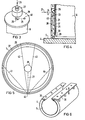
- 1 denotes a device for converting stored image signals. It consists of a light source 2, which is passed via a scanning device 3 onto a film 5 (FIG. 2) fastened in a drum 4 and serving as a storage disk. The light released there then reaches an electron multiplier 6. The signals emitted by the multiplier pass via an amplifier 7, an analog-digital converter 8 into an image processing device 9. The latter has a microprocessor at the input of line 10.1 from the analog-digital converter 8 10 on. This one. is connected via a line 11 to a memory 12, which in turn has a line 13 to a computer 14.
- the image signals go via a line 15 to a television monitor 16 and generate a visible image on its screen 17, which image can be viewed or fixed with a camera 18, for example.
- a 30 mW helium-neon (He-Ne) laser is used as the light source 2. It is located in a mounting tube 20 and emits a beam 21 drawn as a dashed line to an expansion system 22 which expands the beam 21 from 1 mm in diameter to 4 mm. The beam 21 then arrives in a focusing device 23, which focuses the beam 21 on the surface of the film 5 to be scanned. The beam 21 ge then reaches through a cylindrical lens 24, which acts as an asticmatism correction. From there, the beam 21 passes through a cavity 25 of the shaft 26 of a motor 27 through to a deflecting mirror 28 and then through a light guide plate 29 and out of its side wall 29.2 onto the surface to be scanned slide 5.
- He-Ne helium-neon
- the plate 29 represents a compact light guide in which the gaps in a light guide composed of fibers between the fibers are filled, so that it in contrast, has increased effectiveness.
- the multiplier 6 is fixedly connected via its mounting tube 30 and a bracket 31 to the mounting tube 20 of the light source 2, so that a stable assignment is given and a longitudinal displacement of the drum 4 is possible.
- the scanning beam 21 is expanded by the expansion system 22 by means of a spatial filter (not shown separately) from a diameter of 1 mm to 4 mm. Subsequently, the beam 21 in the apparatus 23 is fo-kussiert so that it has a diameter of 30 microns has when impinging on the surface of the film 5 /.
- the scanning beam 21 passes through the cavity 25 in the shaft 26 of the engine (or turbine).
- the motor 27 is coupled to a coordinate transmitter (angle encoder) which specifies the location (pixel number) within the line for the image reading. For this purpose, the synchronization line from the microprocessor 10 to the light distributor 3 is available.
- the deflecting mirror 28 is embedded in a glass cylinder 33 which is glued to the elongated shaft 26 of the motor 27.
- the cylinder 33 is almost the size of that for the deflection of the beam 21 in the plate 29 provided hole.
- an astigmatism of the beam path of the scanning beam is avoided.
- the residual astigmatism remaining through the air gap is corrected by a weakly refractive cylindrical lens 24.
- This lens 24 is located on the entry side of the scanning beam into the cavity 25 of the shaft of the motor. If necessary, this fine correction can also be designed to be displaceable, as indicated by the double arrow 34.
- the mirror need not be precisely adjusted. It is sufficient to cement two bevelled blanks, the bevelled surface of the one being previously polished, mirrored and provided with a protective layer. The blank thus produced is then finished.
- the astigmatism arises from the air gap, since the cylinder curvature of the hole and the mirror cylinder are somewhat different.
- a light guide rod can be used in any holder, the outlet side of which has exactly the curvature of the hole, then an additional correction is unnecessary.
- the light guide plate 29 is preferably made of quartz glass, because the light triggered on the film 5 is guided particularly well through this.
- the distance between the outer surface of the disk 29 and the surface of the film 5 is 0.5 mm.
- the plate 29 has recesses for the mounting angles 35 and 36 (FIG. 6) of the drum 4 on its outer boundary.
- the lateral edge of the plate 29 is at a sufficiently small distance from the surface of the film 5, approximately 90% of the light released in the film enters the plate 29. There the light is completely transmitted through total reflection (refractive index against air greater than 1, 42 as in plexiglass or quartz glass). The missing remaining 10% results from reflection losses on the surface of the plate 29.
- the light is transferred through a light guide at its end to the light receiver, for example an electron multiplier.
- the lateral coupling of the plate 29 to the electron multiplier 6 according to the invention has the effect that the total reflection on the side facing it is eliminated with the match of the refractive index of the adjoining parts. In this way, the light which is triggered on the film 5 reaches the receiver located in the window 30 of the electron multiplier 6 via very short paths, i.e. the photocathode 37 of the electron multiplier 6.
- the light path of the beam 21 is guided through the plate 29. It triggers light on the film 5, which then reaches the photocathode 37 of the electron multiplier 6 via the beam path 38.
- the beam traverses the filter layer 39, which serves to prevent any scattered light from the beam 21 from entering the photocathode 37. Laser light predominantly scattered back from fluorescent material increases the recording signal and is therefore harmless.
- the beam 40 indicates the beam path which leads to the loss of light in unfavorable conditions.
- a 2 mm thick plate made of filter glass BG 3 is cemented, which as a filter 39 causes scattered light of the scanning beam 21 to be absorbed.
- a 3 mm thick filter is used which transmits 70% of the stimulated light of 390 nm triggered on the film 5 (when BaFl (ClBr) is used as storage material).
- the scanning light of 630 nm is absorbed to less than the fraction 10-12.
- the light paths in the filter for the scanning light are longer and vary more.
- FIG. 9 shows a simple embodiment of the light guide plates 29.1.
- the parts which correspond to FIG. 2 are identified by adding .1.
- the laser beam 21.1 is guided over a mirror 28.1 such that it extends outside the plate 29.1 and is guided very close to the outer edge 29.3 of the light guide plate onto the phosphor of the film 5.1.
- Through an angle from about 10 to 20 0 between the laterally deflected beam 21.1 and its selected in the arrangement of Figure 2 deflection by 90 ° it is achieved that in spite of alignment tolerances of focus in the phosphor of the film 5.1, at least not in front of the light guide plate 29.1. This means that at least all light in the half space behind the vertical is received in the light guide 29.1.
- the light guide plate 29.1 With a thickness of the light guide plate 29.1 of 5 mm, a distance of 1 to 2 mm from its lateral boundary is recommended so that the adjustment is not too critical.
- the light guide plate 29.1 need only be well polished on all surfaces and does not need to be of optical quality in the material either. For example, it can be made from quartz glass that contains streaks.
- the light yield in this embodiment is lower than in the arrangements of FIGS. 1 to 5, because approximately half of the light released in the storage plate is lost due to the asymmetrical position of the plate relative to the light exit point.
- the mirror 28.4 is rotated by means of a motor 27.4, which is arranged upstream of the expansion system 22.4 and the focusing device 23.4.
- the motor 27.4 can be stored between the focusing device 23.4 and the electron multiplier 6.4, because the scanning beam 21.4 can be deflected laterally past the motor 27.4.
- FIG. 11 shows an embodiment of the invention with which an X-ray film 5.6 can be converted into a television pulse train.
- the bracket drum 4.6 is made of glass, ie from transparent material.
- the film can also be stretched out in a cylindrical shape without a special holder if it is sufficient has mechanical stability.
- the light falling through the film 4.6 from the beam 21.6 reaches a mirror surface 50.6, which is placed around the outside of the film 4.6, so that it forms a cone cutout which encloses an angle of 45 ° with the axis.
- the light guide 29.6 need not have optical precision.
- the mirror surface 50.6 does not need to be exactly flat either, because light which deviates from the axial direction of the cylinder 29.6 and hits its wall is guided further to the photocathode 37.6 of the electron multiplier 6.6 by total reflection. The same applies with regard to the divergence of the light beam 21.6, depending on the focusing conditions and diffraction phenomena of the laser beam on film grains.
- the mirror surface 50.6 can be replaced by a difus reflecting surface, for example by an application of titanium dioxide (Ti0 2 ), which is bound by epoxy resin.
- Ti0 2 titanium dioxide
- Such a layer causes more than 50% of the light falling on the reflector to be transmitted. Some exits because the critical angle of total reflection is not reached. Further losses due to total reflection, which can occur at the end of the light guide 29.6 facing the electron multiplier 6.6, can be avoided by cementing this end to the entrance window 30.6 of the electron multiplier 6.6. Due to diffuse reflection, the light spreads out sideways and illuminates the photo cathode 37.6 almost evenly. In this way, image artifacts due to local damage (scratches, dust, etc.) of the light guide 29.6 and due to local irregularities in the photocathode 37.6 are avoided.
- FIG. 12 An arrangement is drawn in FIG. 12 in which a small electron multiplier 6.7 is used.
- the light guide 29.7 is closed by a plate 51, which consists of plexiglass.
- the light released in the storage layer 5.7 is directed in the light guide 29.7 via three conical mirror surfaces 50.7, 52, 53 to the electron multiplier 6.7.
- the electron multiplier 6.8 has a hemispherical cathode 37.8. This simplifies the light guide system 29.8, in that only two mirrors 50.8 and 52.8 are required to transmit the triggered light. Similar arrangements are achieved with electron multipliers with so-called side cathodes, i.e. those multipliers in which a flat input window is present, but in which the cathode also occupies parts of the cylindrical side wall of the electron multiplier beyond the input window. In the embodiment according to FIG. 4, two slit diaphragms 54 and 55 are also arranged between the entrance mirror 50.8 and the storage film 5.8 to be triggered. These have the effect that only light coming directly through the film 5.8 enters the light guide 29.8. Stray light, on the other hand, is largely hidden.
- FIG. 14 shows an arrangement in which two mirrors 50.9 and 56 are assigned to the read point.
- the mirror 50.9 is assigned to the light guide 29.9 and the mirror 56 to the light guide 57, both of which lead to the input window 30.9 of the electron multiplier 6.9.
- the two mirrors 50.9 and 56 Through the use of the two mirrors 50.9 and 56, over 80% of the light released in the storage layer 59 by means of the read-out beam 21.9 is collected and is transferred to the electron multiplier 6.9 headed. While the arrangement of the mirror 50.9 is already inclined at 45 ° to FIG. 12, the mirror 56 has a curved shape, which is more clearly expressed in FIG. 15.
- the light guide 57 consists of a 10 mm thick tube made of quartz, which is 1.5 mm away from the film 5.9. The point of incidence 60 of the scanning beam 21.9 is then 5 mm from the input 58 of the light guide 57.
- the mirror 56 consists of a ring made of transparent material, such as glass or plexiglass (surface mirror : gel), which has a passage 57.1 for the read beam 21.9.
- the surface On its side facing the surface to be read out of the film 5.9, the surface is designed in the shape of a part which appears in the form of a circular arc, a part which is flat. The shape is not very critical since all light falling into the light guide is directed.
- the reflection is achieved by means of a layer 62, which in the present example is an aluminum surface mirror of a known type.
- the embodiment according to FIG. 14 with the two light guides 29.9 and 57 permits both reading out of images stored in a phosphorescent layer and reading out film images in transmitted light. Since the If the light of the beam 21.9 penetrating through a film is much greater than the light that can be stimulated in the phosphor of a storage film 5.9, it is expedient to make the scanning beam 21.9 weaker when reading film images. This can be done using a filter, such as gray glass. In the simpler arrangement of a gray glass filter in the beam path of the scanning beam 21.9, the light guide 29.9 is to be covered by a slide when reading out images stored in the phosphorescent substance of a storage film 5.9.
Landscapes
- Engineering & Computer Science (AREA)
- Multimedia (AREA)
- Signal Processing (AREA)
- Physics & Mathematics (AREA)
- General Physics & Mathematics (AREA)
- Facsimile Scanning Arrangements (AREA)
- Conversion Of X-Rays Into Visible Images (AREA)
- Transforming Light Signals Into Electric Signals (AREA)
Applications Claiming Priority (2)
| Application Number | Priority Date | Filing Date | Title |
|---|---|---|---|
| DE3435315 | 1984-09-26 | ||
| DE3435315 | 1984-09-26 |
Publications (2)
| Publication Number | Publication Date |
|---|---|
| EP0179247A1 true EP0179247A1 (fr) | 1986-04-30 |
| EP0179247B1 EP0179247B1 (fr) | 1989-04-26 |
Family
ID=6246409
Family Applications (1)
| Application Number | Title | Priority Date | Filing Date |
|---|---|---|---|
| EP85111422A Expired EP0179247B1 (fr) | 1984-09-26 | 1985-09-10 | Dispositif de conversion des informations d'une image de rayonnement enregistrée sur une cible en une suite de signaux de télévision |
Country Status (4)
| Country | Link |
|---|---|
| US (1) | US4692813A (fr) |
| EP (1) | EP0179247B1 (fr) |
| JP (1) | JPS6184961A (fr) |
| DE (2) | DE8428330U1 (fr) |
Cited By (2)
| Publication number | Priority date | Publication date | Assignee | Title |
|---|---|---|---|---|
| EP0282719A1 (fr) * | 1987-02-17 | 1988-09-21 | Siemens Aktiengesellschaft | Appareil d'analyse pour feuilles lumineuses de stockage |
| DE19601524A1 (de) * | 1996-01-17 | 1997-07-24 | Hell Ag Linotype | Einen gesteuerten Asynchronmotorantrieb für einen Trommelscanner, dessen Rotor als Hohlwelle zur Anordnung der Innenbeleuchtungseinrichtung ausgerichtet ist |
Families Citing this family (12)
| Publication number | Priority date | Publication date | Assignee | Title |
|---|---|---|---|---|
| JP2524512B2 (ja) * | 1988-02-10 | 1996-08-14 | 富士写真フイルム株式会社 | 画像読取方法 |
| US5635728A (en) * | 1995-06-19 | 1997-06-03 | Denoptix, Inc. | Rotating scanner system for reading multiple storage layer radiation screens |
| US5895905A (en) * | 1997-02-25 | 1999-04-20 | Logitech, Inc. | Scanner with an internal motor and a contact image sensor |
| IL122269A (en) * | 1997-11-20 | 2001-03-19 | Digident Ltd | Scanning apparatus |
| US6624438B2 (en) | 1997-11-20 | 2003-09-23 | Orex Computed Radiography Ltd. | Scanning apparatus |
| KR20010110408A (ko) | 1998-11-25 | 2001-12-13 | 추후제출 | 단일 헤드를 갖는 형광 스크린 스캐닝 장치 |
| DE19942211C2 (de) * | 1999-09-03 | 2002-02-07 | Duerr Dental Gmbh Co Kg | Vorrichtung zum Auslesen von biegbaren Speicherfolien |
| DE10044425C2 (de) * | 2000-09-08 | 2003-01-09 | Siemens Ag | Verfahren zur Herstellung einer Leuchstoffschicht |
| US7381980B2 (en) * | 2003-01-09 | 2008-06-03 | Idexx Laboratories, Inc. | Method and apparatus for improving a computed radiography image |
| US20050012057A1 (en) * | 2003-05-08 | 2005-01-20 | Alara, Inc. | Method and apparatus for radiation image erasure |
| US7982202B2 (en) * | 2009-03-27 | 2011-07-19 | Carestream Health, Inc. | Enhanced light detector for computed radiography |
| DE102010064136A1 (de) | 2010-08-25 | 2012-03-01 | Michael Thoms | Verfahren und Vorrichtung zum Auslesen von in einem Speicherleuchtstoff eines Speichermediums gespeicherten Bildinformationen |
Citations (5)
| Publication number | Priority date | Publication date | Assignee | Title |
|---|---|---|---|---|
| DE579826C (de) * | 1927-04-07 | 1933-07-06 | Telefunken Gmbh | Verfahren zur Faksimile-UEbertragung mit Hilfe von zylindrischen Bildtraegern, die zur Aufnahme zusammenhaengender Bildstreifen dienen |
| DE2044606A1 (de) * | 1969-09-11 | 1971-04-29 | Etat Francais, vertreten durch den Mimstre des Armees (Armement), Paris | Optische Bank zur Schraubenlinien förmigen Abtastung einer Vorlage, lnsbe sondere eines Filmnegativs |
| DE2263209A1 (de) * | 1971-12-24 | 1973-07-12 | Nippon Telegraph & Telephone | Photoelektrische einrichtung zur bilduebertragung und bildaufzeichnung |
| US3859527A (en) * | 1973-01-02 | 1975-01-07 | Eastman Kodak Co | Apparatus and method for producing images corresponding to patterns of high energy radiation |
| EP0098574A2 (fr) * | 1982-07-06 | 1984-01-18 | Fuji Photo Film Co., Ltd. | Procédé et appareil pour la lecture d'images de radiation |
Family Cites Families (6)
| Publication number | Priority date | Publication date | Assignee | Title |
|---|---|---|---|---|
| US2800527A (en) * | 1950-05-17 | 1957-07-23 | Rca Corp | Multiple pickup facsimile scanner |
| GB1382124A (en) * | 1972-05-19 | 1975-01-29 | Crosfield Electronics Ltd | Scanners for image reproduction |
| US4131916A (en) * | 1975-12-31 | 1978-12-26 | Logetronics, Inc. | Pneumatically actuated image scanning reader/writer |
| US4346295A (en) * | 1978-12-26 | 1982-08-24 | Fuji Photo Film Co., Ltd. | Radiation image read out device |
| CA1192674A (fr) * | 1981-10-16 | 1985-08-27 | Hisatoyo Kato | Systeme d'enregistrement et de lecture d'images par rayonnement |
| US4479147A (en) * | 1982-06-02 | 1984-10-23 | Crosfield Data Systems, Inc. | Method of and apparatus for feeding and positioning material to be scanned |
-
1984
- 1984-09-26 DE DE8428330U patent/DE8428330U1/de not_active Expired
-
1985
- 1985-09-10 DE DE8585111422T patent/DE3569860D1/de not_active Expired
- 1985-09-10 EP EP85111422A patent/EP0179247B1/fr not_active Expired
- 1985-09-18 US US06/777,438 patent/US4692813A/en not_active Expired - Fee Related
- 1985-09-24 JP JP60210895A patent/JPS6184961A/ja active Pending
Patent Citations (5)
| Publication number | Priority date | Publication date | Assignee | Title |
|---|---|---|---|---|
| DE579826C (de) * | 1927-04-07 | 1933-07-06 | Telefunken Gmbh | Verfahren zur Faksimile-UEbertragung mit Hilfe von zylindrischen Bildtraegern, die zur Aufnahme zusammenhaengender Bildstreifen dienen |
| DE2044606A1 (de) * | 1969-09-11 | 1971-04-29 | Etat Francais, vertreten durch den Mimstre des Armees (Armement), Paris | Optische Bank zur Schraubenlinien förmigen Abtastung einer Vorlage, lnsbe sondere eines Filmnegativs |
| DE2263209A1 (de) * | 1971-12-24 | 1973-07-12 | Nippon Telegraph & Telephone | Photoelektrische einrichtung zur bilduebertragung und bildaufzeichnung |
| US3859527A (en) * | 1973-01-02 | 1975-01-07 | Eastman Kodak Co | Apparatus and method for producing images corresponding to patterns of high energy radiation |
| EP0098574A2 (fr) * | 1982-07-06 | 1984-01-18 | Fuji Photo Film Co., Ltd. | Procédé et appareil pour la lecture d'images de radiation |
Cited By (2)
| Publication number | Priority date | Publication date | Assignee | Title |
|---|---|---|---|---|
| EP0282719A1 (fr) * | 1987-02-17 | 1988-09-21 | Siemens Aktiengesellschaft | Appareil d'analyse pour feuilles lumineuses de stockage |
| DE19601524A1 (de) * | 1996-01-17 | 1997-07-24 | Hell Ag Linotype | Einen gesteuerten Asynchronmotorantrieb für einen Trommelscanner, dessen Rotor als Hohlwelle zur Anordnung der Innenbeleuchtungseinrichtung ausgerichtet ist |
Also Published As
| Publication number | Publication date |
|---|---|
| EP0179247B1 (fr) | 1989-04-26 |
| US4692813A (en) | 1987-09-08 |
| DE8428330U1 (de) | 1986-03-13 |
| DE3569860D1 (en) | 1989-06-01 |
| JPS6184961A (ja) | 1986-04-30 |
Similar Documents
| Publication | Publication Date | Title |
|---|---|---|
| DE2951501C2 (de) | Strahlungsbildlesevorrichtung | |
| EP0213428B1 (fr) | Dispositif d'acquisition d'images rayon X par radiographie numérique | |
| DE19859747C1 (de) | Vorrichtung und Verfahren zum Auslesen von in einer Phosphorschicht abgespeicherten Informationen | |
| EP0179247B1 (fr) | Dispositif de conversion des informations d'une image de rayonnement enregistrée sur une cible en une suite de signaux de télévision | |
| DE2105259A1 (de) | Gerat fur die Röntgenstrahlenfotografie | |
| DE3686849T2 (de) | Bildaufzeichnungs- und auslesegeraet fuer lichtanregbare leuchtstoffe. | |
| DE3874899T2 (de) | Lichtleiterbuendel mit verbessertem endstueck. | |
| DE69409235T2 (de) | Vorrichtung zum Auslesen eines Speicherphosphor-Aufzeichnungsträgers | |
| EP0282719B1 (fr) | Appareil d'analyse pour feuilles lumineuses de stockage | |
| DE2000116A1 (de) | Eingangsschirm fuer Bildvorrichtungen | |
| EP0819965B1 (fr) | Méthode et appareil pour enregistrer une information d'images | |
| DE69615523T2 (de) | Vorrichtung zum Auslesen eines Strahlungsbildes | |
| DE69002229T2 (de) | Telezentrisches abtasten für transparente speicherphosphore. | |
| DE4213556C2 (de) | Einrichtung zur optischen Abtastung eines Aufzeichnungsträgers, insbesondere einer Phosphorspeicherplatte | |
| DE69212823T2 (de) | Lesegerät und lichtempfanger für bildern hergestellt mittels stimulierte radiation | |
| DE3332909A1 (de) | Anordnung zum beleuchten einer zeile eines informationstraegers | |
| DE69309075T2 (de) | Vorrichtung zum Auslesen von Strahlungsbildern durch Photostimulierung | |
| DE69817370T2 (de) | Optische abtastvorrichtung mit einem lesekopf | |
| DE102011016601A1 (de) | Vorrichtung zum Auslesen von Speicherfolien | |
| WO2009146787A1 (fr) | Dispositif permettant de lire des écrans à mémoire pour images de radiographie | |
| EP0970404B1 (fr) | Systeme pour selectionner des substances luminescentes accumulatrices photostimulables | |
| DE19964445B4 (de) | Vorrichtung und Verfahren zum Auslesen von in einer Speicherschicht abgespeicherten Informationen | |
| DE69728461T2 (de) | Verfahren und Apparat zum auslesen von Strahlungsbildern | |
| EP0667540A1 (fr) | Dispositif pour la reproduction d'image dans un écran luminescent stimulable | |
| DE19962774B4 (de) | Vorrichtung und Verfahren zum Auslesen von in einer Speicherschicht abgespeicherten Informationen |
Legal Events
| Date | Code | Title | Description |
|---|---|---|---|
| PUAI | Public reference made under article 153(3) epc to a published international application that has entered the european phase |
Free format text: ORIGINAL CODE: 0009012 |
|
| AK | Designated contracting states |
Kind code of ref document: A1 Designated state(s): DE FR IT |
|
| 17P | Request for examination filed |
Effective date: 19860527 |
|
| 17Q | First examination report despatched |
Effective date: 19880225 |
|
| GRAA | (expected) grant |
Free format text: ORIGINAL CODE: 0009210 |
|
| AK | Designated contracting states |
Kind code of ref document: B1 Designated state(s): DE FR IT |
|
| REF | Corresponds to: |
Ref document number: 3569860 Country of ref document: DE Date of ref document: 19890601 |
|
| ITF | It: translation for a ep patent filed | ||
| ET | Fr: translation filed | ||
| PLBE | No opposition filed within time limit |
Free format text: ORIGINAL CODE: 0009261 |
|
| STAA | Information on the status of an ep patent application or granted ep patent |
Free format text: STATUS: NO OPPOSITION FILED WITHIN TIME LIMIT |
|
| 26N | No opposition filed | ||
| ITTA | It: last paid annual fee | ||
| PGFP | Annual fee paid to national office [announced via postgrant information from national office to epo] |
Ref country code: FR Payment date: 19910917 Year of fee payment: 7 |
|
| PGFP | Annual fee paid to national office [announced via postgrant information from national office to epo] |
Ref country code: DE Payment date: 19911127 Year of fee payment: 7 |
|
| PG25 | Lapsed in a contracting state [announced via postgrant information from national office to epo] |
Ref country code: FR Effective date: 19930528 |
|
| PG25 | Lapsed in a contracting state [announced via postgrant information from national office to epo] |
Ref country code: DE Effective date: 19930602 |
|
| REG | Reference to a national code |
Ref country code: FR Ref legal event code: ST |