EP0179271B1 - Dispositif d'alimentation pour le remplissage d'installations de chauffage fermées - Google Patents
Dispositif d'alimentation pour le remplissage d'installations de chauffage fermées Download PDFInfo
- Publication number
- EP0179271B1 EP0179271B1 EP85111774A EP85111774A EP0179271B1 EP 0179271 B1 EP0179271 B1 EP 0179271B1 EP 85111774 A EP85111774 A EP 85111774A EP 85111774 A EP85111774 A EP 85111774A EP 0179271 B1 EP0179271 B1 EP 0179271B1
- Authority
- EP
- European Patent Office
- Prior art keywords
- pressure
- outlet
- control
- fresh water
- tube
- Prior art date
- Legal status (The legal status is an assumption and is not a legal conclusion. Google has not performed a legal analysis and makes no representation as to the accuracy of the status listed.)
- Expired - Lifetime
Links
- 238000010438 heat treatment Methods 0.000 title claims abstract description 30
- 239000007788 liquid Substances 0.000 title 1
- 239000013505 freshwater Substances 0.000 claims abstract description 23
- 238000000926 separation method Methods 0.000 claims abstract description 18
- 238000011144 upstream manufacturing Methods 0.000 claims abstract description 3
- 238000009434 installation Methods 0.000 claims abstract 8
- 230000000284 resting effect Effects 0.000 claims abstract 7
- 239000003638 chemical reducing agent Substances 0.000 description 38
- 238000007789 sealing Methods 0.000 description 8
- 238000013459 approach Methods 0.000 description 3
- 238000005429 filling process Methods 0.000 description 3
- XLYOFNOQVPJJNP-UHFFFAOYSA-N water Substances O XLYOFNOQVPJJNP-UHFFFAOYSA-N 0.000 description 3
- 230000007423 decrease Effects 0.000 description 2
- 238000011161 development Methods 0.000 description 2
- 230000018109 developmental process Effects 0.000 description 2
- 230000000694 effects Effects 0.000 description 2
- 239000008236 heating water Substances 0.000 description 2
- 238000013022 venting Methods 0.000 description 2
- 230000033228 biological regulation Effects 0.000 description 1
- 230000006835 compression Effects 0.000 description 1
- 238000007906 compression Methods 0.000 description 1
- 238000013461 design Methods 0.000 description 1
- 239000012528 membrane Substances 0.000 description 1
- 238000000034 method Methods 0.000 description 1
- 238000012986 modification Methods 0.000 description 1
- 230000004048 modification Effects 0.000 description 1
- 239000004449 solid propellant Substances 0.000 description 1
- 238000012546 transfer Methods 0.000 description 1
- 238000011179 visual inspection Methods 0.000 description 1
Images
Classifications
-
- F—MECHANICAL ENGINEERING; LIGHTING; HEATING; WEAPONS; BLASTING
- F24—HEATING; RANGES; VENTILATING
- F24D—DOMESTIC- OR SPACE-HEATING SYSTEMS, e.g. CENTRAL HEATING SYSTEMS; DOMESTIC HOT-WATER SUPPLY SYSTEMS; ELEMENTS OR COMPONENTS THEREFOR
- F24D3/00—Hot-water central heating systems
- F24D3/10—Feed-line arrangements, e.g. providing for heat-accumulator tanks, expansion tanks ; Hydraulic components of a central heating system
- F24D3/1083—Filling valves or arrangements for filling
-
- F—MECHANICAL ENGINEERING; LIGHTING; HEATING; WEAPONS; BLASTING
- F24—HEATING; RANGES; VENTILATING
- F24D—DOMESTIC- OR SPACE-HEATING SYSTEMS, e.g. CENTRAL HEATING SYSTEMS; DOMESTIC HOT-WATER SUPPLY SYSTEMS; ELEMENTS OR COMPONENTS THEREFOR
- F24D19/00—Details
- F24D19/10—Arrangement or mounting of control or safety devices
- F24D19/1006—Arrangement or mounting of control or safety devices for water heating systems
- F24D19/1009—Arrangement or mounting of control or safety devices for water heating systems for central heating
- F24D19/1015—Arrangement or mounting of control or safety devices for water heating systems for central heating using a valve or valves
- F24D19/1036—Having differential pressure measurement facilities
-
- F—MECHANICAL ENGINEERING; LIGHTING; HEATING; WEAPONS; BLASTING
- F24—HEATING; RANGES; VENTILATING
- F24D—DOMESTIC- OR SPACE-HEATING SYSTEMS, e.g. CENTRAL HEATING SYSTEMS; DOMESTIC HOT-WATER SUPPLY SYSTEMS; ELEMENTS OR COMPONENTS THEREFOR
- F24D3/00—Hot-water central heating systems
- F24D3/10—Feed-line arrangements, e.g. providing for heat-accumulator tanks, expansion tanks ; Hydraulic components of a central heating system
Definitions
- Pressure reducers of this type are used for filling a closed heating system and serve to fill this system automatically.
- the pressure reducer is set to a predetermined pressure and closes when this pressure is reached, so that the pressure in the closed system cannot exceed a predetermined value.
- the backflow preventer is provided between the outlet side of the pressure reducer and the closed system and prevents the filling medium or water from the closed system from being pushed back into the supply line if the inlet pressure of the pressure reducer drops below the internal pressure of the closed system.
- the known filling device is not constantly connected to the closed system according to existing regulations, but only via a hose line to be removed after the filling process.
- This has a disadvantageous effect, particularly in the case of larger systems, because the venting process of such systems takes a long time, possibly up to 6 months, and during this venting period, filling medium or water must be constantly refilled into the system so that the required pressure within the closed system is maintained. Repeated refilling operations of this type are tedious, and for this reason attempts have been made to automatically fill the closed system, in compliance with the legal provisions, by connecting an unpressurized water tank, which is controlled by a float valve, to the closed system via a booster pump becomes.
- a booster pump must be used, although the pressure in the supply line itself would be sufficient to ensure the necessary filling pressure of the closed system.
- a thermally controlled safety device for boilers in closed heating systems is known from EP-A2-0 041 163.
- a boiler heated with solid fuels is provided.
- the aim is to prevent overpressure from occurring in the event of overtemperature, which leads to the safety valve responding. For this reason, cold fresh water from the supply line is let into the system of the heating system if the temperature is too high, and warm heating water is drained off at the same time via a drain.
- a pipe separator is arranged in the fresh water supply line. The pipe separator disconnects the connection between the fresh water pipe and the heating system, so that an observable separation point is created between them. The separation point is bridged only by a water-carrying, movable link in the form of a sliding sleeve for fresh water supply and the connection between the fresh water line and the heating system is established.
- the pipe separator contains a flow connection with a large cross section and a control connection with a small cross section.
- the flow connection is directly connected to the outlet of a pressure reducer.
- the control connection is controlled by a poppet valve.
- the poppet valve is controlled by the actuator of a temperature sensor that responds to the boiler temperature. At the same time, this actuator controls a "thermal discharge safety device", which causes the discharge of hot heating water.
- the pipe separator contains in the known arrangement as an actuating piston an annular piston which is guided outside in a cylinder and inside on a tube.
- the pipe is connected at one end to the outlet of the pressure reducer and closed at the other end.
- the tube has side outlets.
- a sleeve is connected to the actuating piston, which sleeve is displaceably guided on the tube and, with its end, can be inserted into a receptacle on the heating system in a sealing manner beyond the separation point.
- the inside of the sleeve has an annular recess, via which the cable outlets of the tube come into connection with the bore of the sleeve when the end of the sleeve is inserted into the receptacle in its operating position.
- a backflow preventer is provided on the heating system side of the separation point.
- the invention has for its object a To create automatic filling device of the type mentioned, which can be connected directly to the supply line and allows the pressure in the supply line to be used to automatically fill the closed system.
- the filling device designed according to the invention represents a unitary assembly which uses the pipe separator to establish a connection between the supply line and the closed system.
- This module can always be left in connection with the supply line and the closed system without the risk that the filling medium is pressed back out of the closed system into the supply line.
- the interposition of the pipe separator controlled by the control arrangement brings about a reliable separation of the supply line from the closed system when its predetermined internal pressure has been reached.
- the pipe separator ensures that filling medium is pressed back into the supply line from the filled system if the pressure in the supply line drops below the internal pressure prevailing in the filled system.
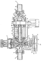
- the illustration shows a longitudinal section through the exemplary embodiment of the filling device.
- This consists of an essentially conventionally constructed pressure reducer, which is generally designated 1.
- This pressure reducer is set to a pressure which is matched to the predetermined internal pressure or filling pressure of the closed system.
- the structure of the pressure reducer 1 and its function and setting are known and are therefore not described in detail.
- the pressure reducer On the input side, the pressure reducer is provided with a connecting piece 2, to which a connecting piece 4 is fastened by means of a union nut 3, by means of which the pressure reducer 1 can be permanently connected to a supply line, not shown.
- a shoulder 5 is fixedly connected to the pressure reducer 1, which receives the pipe separator described below.
- a backflow preventer In the free end 6 of the neck 5, a backflow preventer, generally designated 7, is inserted by means of a connecting part 8.
- the backflow preventer 7 carries at the other end on a connecting piece 9 a union nut 10, through which a connector 11 is held, by means of which the entire filling device can be permanently connected as a uniform fitting to the closed system, not shown.
- the backflow preventer 7 contains a spring-loaded closing body which is held against the seat by the spring load in the closing system and which blocks the backflow preventer 7 against the shoulder 5 and thus against the pressure reducer 1.
- the connecting part 8 of the backflow preventer 7 contains a bypass line 13 which bypasses the closing body 12 and opens into an annular chamber 14, in which the internal pressure of the closed system therefore prevails.
- a separation point 15 is installed, which allows a visual inspection of the space between the pipe separator 20 described below and the check valve 7 and in the usual and therefore not particularly described Is trained.
- a leak drain pipe 16 branches off from the attachment 5 and is connected in a conventional manner to an existing disposal line.
- the pressure reducer 1 also carries on one side a not particularly marked setting device of conventional design for setting an outlet pressure which is matched to the predetermined internal pressure or filling pressure of the closed system. On the opposite side, the pressure reducer 1 carries a control arrangement 40, described in detail below, for controlling the pipe separator 20.
- the approach 5 of the pressure reducer 1 is designed so that it serves as a housing for the pipe separator 20.
- This pipe separator 20 consists of a pipe 21 which is closed on one side and which is inserted in a sealing manner in the attachment 5 on the pressure reducer 1.
- At the closed end of the tube 21 through openings 22 are formed in its side wall, three of which can be seen in the figure.
- An annular piston 23 is displaceable on the tube 21 against the force of a spring 24.
- the head 25 of the annular piston 23 faces the pressure reducer 1; the spring 24 acts on the side of the head 25 facing away from the pressure reducer 1 and is supported on an abutment 26, which in the vicinity of the separation point 15 is held on the approach 5.
- the annular piston 23 also has a recess 27 in its wall and forms an annular gap 28 between the recess 27 and the through openings 22 in the tube 21 which is closed on one side.
- the pipe separator 20 is shown in its closed position in the figure. In this position, the annular piston 23 lies in a sealing manner against the tube 21, which is closed on one side, so that the through openings 22 of the tube 21 are closed.
- the connecting part 8 of the backflow preventer 7 contains, on the side opposite the pipe separator 20, a recess 29 which is adapted to the annular piston 23 of the pipe separator 20 and receives it in its second or open position.
- the recess 29 is provided with sealing means 30, by means of which the annular piston 23 is sealingly inserted into the recess 29 in the second or open position.
- the control arrangement 40 consists essentially of control valves and a differential pressure transmitter for controlling the control valves; the control arrangement 40 is arranged on the pressure regulator 1 on the side opposite the adjusting device.
- the differential pressure transmitter 41 essentially consists of two chambers 42, 43 which are separated from one another by a movable wall 44 in the form of a membrane.
- the chamber 42 facing away from the pressure reducer 1 is connected to the outlet side of the pressure reducer 1 via a connecting line 45 shown in broken lines.
- the chamber 43 is connected to the ring channel 14 in the connecting part 8 of the check valve 7 via a connecting line 46 shown in broken lines.
- the differential pressure sensor 41 is fastened in a sealing manner to a further extension 48 of the pressure reducer 1 by means of a union nut 47.
- the movable wall 44 carries a plate 49 to which a control rod 50 is fastened, which extends sealingly into the interior of the further extension 48 through a sealing body 51.
- a valve seat body 52 is formed in the interior of the pressure reducer 1 on the outlet side thereof in the further extension 48.
- a valve seat 53 of a control valve with a spring-loaded valve body 54 is located on the valve seat body 52 on the side facing away from the pressure difference transmitter 41.
- the valve body 54 is supported by a compression spring which is supported on an opposite part of the pressure reducer 1, in the exemplary embodiment on its single-seat valve. held in closing system on its valve seat 53.
- the valve body 56 is under the action of a tension spring which is arranged on the valve seat body 52 and the valve body 56 in a closed contact with its valve seat 55 holds.
- An axial bore 57 extends through the valve seat body 52, from which a control line 58 branches off between the valve seats 53 and 55, which connects the axial bore 57 and an annular space of the extension 5 and on a side opposite in the head 25 of the annular piston 23 of the pipe separator 20 opens into the annular space 60.
- a relief line 59 extends from the further extension 48, which extends essentially parallel to the control line 58 and extension 5 and extends to the leakage drain pipe 16.
- the control rod 50 of the differential pressure sensor 41 extends sealingly but slidably through the valve body 56 and the valve seat 55 of the relief valve and through the axial bore 57 of the valve seat body 52 and carries at its free end a control body 61 which cooperates with the valve body 54 of the control valve.
- the filling device described above works as follows:
- the figure shows the filling device and the pipe separator 20 in their closed position. Accordingly, the backflow preventer 7 is closed by the closing body 12 against the attachment 5 or the pressure reducing valve 1. Any filling medium escaping from the closing body 12 is drained off through the leakage drain pipe 16.
- the annular piston 23 is brought under the action of the spring 24 into the retracted position in which it closes the through openings 22 of the tube 21 closed on one side in the tube separator 20.
- the internal pressure or filling pressure of the closed system is the same as the outlet pressure of the pressure reducer 1, and therefore the pressures prevailing in the chambers 42 and 43 of the differential pressure sensor 41 are also the same.
- the control rod 51 is thus in its retracted position and the valve body 54 of the control valve on the output side of the pressure reducer 1 is in contact with the valve seat 53.
- the control line 58 and the interior of the extension 5 are depressurized, so that the valve body 56 of the relief valve, the valve seat 55 of which is in close contact.
- the filling medium can then flow out through the axial bore 57 and the valve seat 55 of the relief valve on the valve seat body 52 into the relief line 59 and the spring 24 brings about the resetting of the annular piston 23.
- the valve body 56 After resetting the annular piston 23 and pressure compensation in the control line 58, the valve body 56 the relief valve is brought back into its closing system on its valve seat 55, so that the filling device again assumes the closed position shown in the figure.
- the pipe separator 20 can under certain circumstances also form a part which is separate from the pressure reducer 1 and which is connected to the outlet side of the pressure reducer 1 using conventional connecting means.
- the chamber 43 of the differential pressure sensor 41 can also be connected in any other conceivable way so that the internal pressure or filling pressure prevailing in the closed system is present in this chamber.
- the relief line 59 can also be routed separately from the attachment 5 to the leak drain pipe 16.
- the arrangement of the different lugs and connecting pieces is arbitrary and does not need to be opposite one another in a crosswise manner as in the exemplary embodiment shown.
Landscapes
- Engineering & Computer Science (AREA)
- General Engineering & Computer Science (AREA)
- Chemical & Material Sciences (AREA)
- Thermal Sciences (AREA)
- Combustion & Propulsion (AREA)
- Mechanical Engineering (AREA)
- Physics & Mathematics (AREA)
- Filling Or Discharging Of Gas Storage Vessels (AREA)
- Packaging Of Special Articles (AREA)
- Resistance Heating (AREA)
- Instantaneous Water Boilers, Portable Hot-Water Supply Apparatuses, And Control Of Portable Hot-Water Supply Apparatuses (AREA)
- Thermally Insulated Containers For Foods (AREA)
- Safety Valves (AREA)
- Basic Packing Technique (AREA)
Claims (5)
caractérisé par le fait que
Priority Applications (1)
| Application Number | Priority Date | Filing Date | Title |
|---|---|---|---|
| AT85111774T ATE51955T1 (de) | 1984-09-25 | 1985-09-18 | Fuelleinrichtung zur fuellung von geschlossenen anlagen. |
Applications Claiming Priority (2)
| Application Number | Priority Date | Filing Date | Title |
|---|---|---|---|
| DE19843435127 DE3435127A1 (de) | 1984-09-25 | 1984-09-25 | Fuelleinrichtung zur fuellung von geschlossenen anlagen |
| DE3435127 | 1984-09-25 |
Publications (3)
| Publication Number | Publication Date |
|---|---|
| EP0179271A2 EP0179271A2 (fr) | 1986-04-30 |
| EP0179271A3 EP0179271A3 (en) | 1988-01-07 |
| EP0179271B1 true EP0179271B1 (fr) | 1990-04-11 |
Family
ID=6246291
Family Applications (1)
| Application Number | Title | Priority Date | Filing Date |
|---|---|---|---|
| EP85111774A Expired - Lifetime EP0179271B1 (fr) | 1984-09-25 | 1985-09-18 | Dispositif d'alimentation pour le remplissage d'installations de chauffage fermées |
Country Status (3)
| Country | Link |
|---|---|
| EP (1) | EP0179271B1 (fr) |
| AT (1) | ATE51955T1 (fr) |
| DE (2) | DE3435127A1 (fr) |
Families Citing this family (6)
| Publication number | Priority date | Publication date | Assignee | Title |
|---|---|---|---|---|
| EP0972995A1 (fr) * | 1998-07-16 | 2000-01-19 | Hans Sasserath & Co Kg | Dispositif de remplissage pour remplir un système de chauffage fermé à eau chaude |
| NL1017198C1 (nl) * | 2001-01-26 | 2002-07-29 | Jan Henk Cnossen | Verwarming voor vloeistof. |
| DE10308838A1 (de) * | 2003-02-27 | 2004-09-09 | Hans Sasserath & Co. Kg | Ventilanordnung für einen Rohrtrenner |
| DE102005006790B4 (de) * | 2005-02-14 | 2007-06-06 | Hans Sasserath & Co. Kg | Ventilanordnung mit druckabhängig gesteuertem Ventil |
| GB0607319D0 (en) * | 2006-04-12 | 2006-05-24 | Gledhill Water Storage | Improvements to water heating systems |
| GB2528912A (en) * | 2014-08-02 | 2016-02-10 | Robert Foster | Mechanical filling device 19 |
Family Cites Families (4)
| Publication number | Priority date | Publication date | Assignee | Title |
|---|---|---|---|---|
| DE2018852A1 (de) * | 1970-04-20 | 1971-11-04 | Marx, Heinrich, 6365 Ober-Rosbach; Schubert, Werner, 6376 Oberhöchstadt | Automatische Füllvorrichtung für Heizungs- und Druckanlagen mit doppelter Rückflußverhinderung |
| DE2445200C2 (de) * | 1974-09-21 | 1982-12-23 | Honeywell-Braukmann GmbH, 6950 Mosbach | Füllarmatur, insbesondere für Heizungsanlagen |
| DE3007454A1 (de) * | 1980-02-28 | 1981-09-10 | Hans Sasserath & Co Kg, 4052 Korschenbroich | Armatur zum fuellen von heizungsanlagen |
| DE3020797A1 (de) * | 1980-05-31 | 1981-12-17 | Hans Sasserath & Co Kg, 4052 Korschenbroich | Thermisch gesteuerte sicherheitseinrichtung fuer kessel in geschlossenen heizungsanlagen |
-
1984
- 1984-09-25 DE DE19843435127 patent/DE3435127A1/de not_active Withdrawn
-
1985
- 1985-09-18 AT AT85111774T patent/ATE51955T1/de not_active IP Right Cessation
- 1985-09-18 DE DE8585111774T patent/DE3577136D1/de not_active Expired - Fee Related
- 1985-09-18 EP EP85111774A patent/EP0179271B1/fr not_active Expired - Lifetime
Also Published As
| Publication number | Publication date |
|---|---|
| DE3435127A1 (de) | 1986-04-03 |
| EP0179271A2 (fr) | 1986-04-30 |
| DE3577136D1 (de) | 1990-05-17 |
| ATE51955T1 (de) | 1990-04-15 |
| EP0179271A3 (en) | 1988-01-07 |
Similar Documents
| Publication | Publication Date | Title |
|---|---|---|
| EP1350896B1 (fr) | Arrangement de soupapes pour un disjoncteur hydraulique | |
| EP0038056A2 (fr) | Accouplement à action rapide pour tuyaux souples ou analogues | |
| DE69405286T2 (de) | Wassererhitzer | |
| DE69029322T2 (de) | Universelles steuerventil | |
| EP1681520A2 (fr) | vanne pour de fluide | |
| DE102005051348B4 (de) | Baugruppe zum Zuführen von Wasser zu Heizungsanlagen mit Wassererwärmer | |
| EP0179271B1 (fr) | Dispositif d'alimentation pour le remplissage d'installations de chauffage fermées | |
| DE1600733A1 (de) | Druckminderer | |
| DE102016125734A1 (de) | Regelarmatur | |
| DE202006020891U1 (de) | Sicherheitseinrichtung für Wasserheizsystem | |
| EP1691115A1 (fr) | Ensemble de soupape avec une vanne sensible à la pression | |
| EP1950354B1 (fr) | Séparateur de système | |
| DE102013006051B4 (de) | Adapteranordnung für eine Absperrarmatur | |
| AT502342B1 (de) | Ventil | |
| DE102008056109A1 (de) | Ventil mit einer Einrichtung gegen Wasserschlag | |
| DE202017001847U1 (de) | Druckausgleichsregler | |
| DE19636410B4 (de) | Armatur für Wasserleitungen | |
| DE19650031A1 (de) | Wasserarmatur mit Rückflußverhinderer | |
| DE10235061C1 (de) | Expansionsvorrichtung zur Aufnahme von erwärmtem Trinkwasser | |
| WO1989005382A1 (fr) | Clapet de non-retour, notamment pour conduits d'eau potable | |
| EP0041163B1 (fr) | Dispositif de sécurité commandé thermiquement pour chaudière de chauffage dans des installations de chauffage à circuit hydraulique fermé | |
| EP1193434B1 (fr) | Soupape, en particulier soupape de radiateur | |
| DE102009054583B4 (de) | Anschlussventil und Schlauchbrauseanordnung | |
| CH637854A5 (en) | Frost protection on a high-pressure cleaning device | |
| DE3440588A1 (de) | Temperaturregler fuer waermetauscher |
Legal Events
| Date | Code | Title | Description |
|---|---|---|---|
| PUAI | Public reference made under article 153(3) epc to a published international application that has entered the european phase |
Free format text: ORIGINAL CODE: 0009012 |
|
| AK | Designated contracting states |
Kind code of ref document: A2 Designated state(s): AT CH DE FR LI |
|
| PUAL | Search report despatched |
Free format text: ORIGINAL CODE: 0009013 |
|
| AK | Designated contracting states |
Kind code of ref document: A3 Designated state(s): AT CH DE FR LI |
|
| RHK1 | Main classification (correction) |
Ipc: F24D 3/10 |
|
| 17P | Request for examination filed |
Effective date: 19880407 |
|
| 17Q | First examination report despatched |
Effective date: 19890120 |
|
| GRAA | (expected) grant |
Free format text: ORIGINAL CODE: 0009210 |
|
| AK | Designated contracting states |
Kind code of ref document: B1 Designated state(s): AT CH DE FR LI |
|
| REF | Corresponds to: |
Ref document number: 51955 Country of ref document: AT Date of ref document: 19900415 Kind code of ref document: T |
|
| REF | Corresponds to: |
Ref document number: 3577136 Country of ref document: DE Date of ref document: 19900517 |
|
| ET | Fr: translation filed | ||
| PLBE | No opposition filed within time limit |
Free format text: ORIGINAL CODE: 0009261 |
|
| STAA | Information on the status of an ep patent application or granted ep patent |
Free format text: STATUS: NO OPPOSITION FILED WITHIN TIME LIMIT |
|
| 26N | No opposition filed | ||
| PGFP | Annual fee paid to national office [announced via postgrant information from national office to epo] |
Ref country code: FR Payment date: 19960731 Year of fee payment: 12 |
|
| PGFP | Annual fee paid to national office [announced via postgrant information from national office to epo] |
Ref country code: AT Payment date: 19960913 Year of fee payment: 12 |
|
| PGFP | Annual fee paid to national office [announced via postgrant information from national office to epo] |
Ref country code: CH Payment date: 19961108 Year of fee payment: 12 |
|
| PGFP | Annual fee paid to national office [announced via postgrant information from national office to epo] |
Ref country code: DE Payment date: 19961126 Year of fee payment: 12 |
|
| PG25 | Lapsed in a contracting state [announced via postgrant information from national office to epo] |
Ref country code: AT Free format text: LAPSE BECAUSE OF NON-PAYMENT OF DUE FEES Effective date: 19970918 |
|
| PG25 | Lapsed in a contracting state [announced via postgrant information from national office to epo] |
Ref country code: LI Free format text: LAPSE BECAUSE OF NON-PAYMENT OF DUE FEES Effective date: 19970930 Ref country code: FR Free format text: THE PATENT HAS BEEN ANNULLED BY A DECISION OF A NATIONAL AUTHORITY Effective date: 19970930 Ref country code: CH Free format text: LAPSE BECAUSE OF NON-PAYMENT OF DUE FEES Effective date: 19970930 |
|
| REG | Reference to a national code |
Ref country code: CH Ref legal event code: PL |
|
| PG25 | Lapsed in a contracting state [announced via postgrant information from national office to epo] |
Ref country code: DE Free format text: LAPSE BECAUSE OF NON-PAYMENT OF DUE FEES Effective date: 19980603 |
|
| REG | Reference to a national code |
Ref country code: FR Ref legal event code: ST |