EP0179350A2 - Système de traitement de données - Google Patents
Système de traitement de données Download PDFInfo
- Publication number
- EP0179350A2 EP0179350A2 EP85112744A EP85112744A EP0179350A2 EP 0179350 A2 EP0179350 A2 EP 0179350A2 EP 85112744 A EP85112744 A EP 85112744A EP 85112744 A EP85112744 A EP 85112744A EP 0179350 A2 EP0179350 A2 EP 0179350A2
- Authority
- EP
- European Patent Office
- Prior art keywords
- task
- document
- data
- screen
- tasks
- Prior art date
- Legal status (The legal status is an assumption and is not a legal conclusion. Google has not performed a legal analysis and makes no representation as to the accuracy of the status listed.)
- Withdrawn
Links
Images







Classifications
-
- G—PHYSICS
- G06—COMPUTING OR CALCULATING; COUNTING
- G06F—ELECTRIC DIGITAL DATA PROCESSING
- G06F9/00—Arrangements for program control, e.g. control units
- G06F9/06—Arrangements for program control, e.g. control units using stored programs, i.e. using an internal store of processing equipment to receive or retain programs
- G06F9/46—Multiprogramming arrangements
- G06F9/48—Program initiating; Program switching, e.g. by interrupt
- G06F9/4806—Task transfer initiation or dispatching
- G06F9/4843—Task transfer initiation or dispatching by program, e.g. task dispatcher, supervisor, operating system
- G06F9/4881—Scheduling strategies for dispatcher, e.g. round robin, multi-level priority queues
-
- G—PHYSICS
- G06—COMPUTING OR CALCULATING; COUNTING
- G06F—ELECTRIC DIGITAL DATA PROCESSING
- G06F40/00—Handling natural language data
- G06F40/10—Text processing
- G06F40/103—Formatting, i.e. changing of presentation of documents
- G06F40/117—Tagging; Marking up; Designating a block; Setting of attributes
-
- G—PHYSICS
- G06—COMPUTING OR CALCULATING; COUNTING
- G06F—ELECTRIC DIGITAL DATA PROCESSING
- G06F40/00—Handling natural language data
- G06F40/10—Text processing
- G06F40/12—Use of codes for handling textual entities
- G06F40/123—Storage facilities
-
- G—PHYSICS
- G06—COMPUTING OR CALCULATING; COUNTING
- G06F—ELECTRIC DIGITAL DATA PROCESSING
- G06F40/00—Handling natural language data
- G06F40/10—Text processing
- G06F40/12—Use of codes for handling textual entities
- G06F40/131—Fragmentation of text files, e.g. creating reusable text-blocks; Linking to fragments, e.g. using XInclude; Namespaces
-
- G—PHYSICS
- G06—COMPUTING OR CALCULATING; COUNTING
- G06F—ELECTRIC DIGITAL DATA PROCESSING
- G06F40/00—Handling natural language data
- G06F40/10—Text processing
- G06F40/166—Editing, e.g. inserting or deleting
Definitions
- the present invention relates to a data processing system and, in particular, a system particularly designed for the processing of data in document form.
- Data processing systems of the prior art have generally fallen into one of two classes, the first being general purpose systems designed to perform a wide variety of tasks and the second being specialized systems optimized for a limited range of related tasks.
- a recurring problem with the first class of data processing systems is that many such systems, while having a wide range of applications, may not be as efficient for certain tasks as more specialized system.
- the second class of systems are generally not easily expandable for tasks other than those for which they were originally designed, even when the additional tasks may be related to the original tasks.
- the present invention provides a solution to the above described problems of the prior art, and other problems, by providing a data processing system with features which allows the system to efficiently perform relatively specialized, related tasks, such as document processing, while being readily expandable for other tasks.
- the system incorporates a task control means including a task loader for transferring tasks from a storage means to a system memory means and a task manager responsive to operation of the system for controlling execution of tasks, and a document manager for loading document information in the form of document data structures from the storage means to the system memory and managing access to the document data structures by the tasks.
- the task manager incorporates task control blocks, which are used to manage the execution of tasks, while the document manager incorporates document control blocks which are used to manage access to the document data structures by the tasks.
- each task control block includes an identification field for storing information identifying the corresponding task, a status field for storing information identifying the status of execution of the corresponding task, a priority field for storing information identifying the relative priority of execution of the corresponding task, and a stack pointer field for storing information identifying the location of a stack mechanism usable by the corresponding task.
- the task control blocks reside in a task manager queue mechanism, with the task control blocks being linked by pointers in the preferred sequence of their execution.
- Each document file includes at least one page, and each page including at least one area, wherein each area contains at least one type of information.
- Each area including, in an area containing text information, at least one column for containing text information.
- Each column including at least one line, and each line including a string of at least one text character, a reference to attributes applying to the characters of the string, and references to external data items associated with the line.
- the document file structure includes, for each document file, at least one page block, each page block comprising fields describing the logical dimensions of the page, fields describing the position of a cursor on the page, the cursor position indicating the logical position within the data contained in the page of an operation being performed on the data, a field indicating cursor type, a field describing page layout, and field containing a pointer to an area block.
- Each file structure includes at least one area block, each area block comprising a field for containing a pointer to a next area, fields containing information defining the type of area, fields defining the logical position of the area with the page, fields defining the margins of the area, fields defining the position of text appearing in the area, fields defining the relationship of the area to other areas of the page, and a field for a pointer to a column block.
- the structure further includes at least one column block, comprising a field identifying the format of the text appearing in the area, and at least one field for a pointer to a line block.
- the structure includes at least one line block, each line block comprising at least one field containing a string of at least one text character, a reference to attributes applying to the characters of the string, and references to external data items associated with the line.
- the system also includes a screen manager for creating visual display screens representing data, generally residing in the document structures described above.
- the screen manager includes means responsive to active tasks for creating a screen manager control structure containing information relating each screen to a corresponding task, and, for each screen, information describing certain properties of the screen, and information relating the screen to the data residing in the document structure to be displayed therein.
- the screen manager also includes means responsive to the corresponding tasks and corresponding screen manager control structures to access and display the corresponding data.
- Each screen is described, in the screen manager control structure, by a virtual screen descriptor block and includes at least one viewport onto a portion of the data structure being operated upon by an associated task.
- Each virtual screen descriptor block includes a field identifying the associated screen, a field identifying the associated task, fields describing the associated screen, a field containing a pointer to a first viewport associated with the screen, a field containing an array of numbers identifying all viewports associated with the screen, and a field for containing a pointer to a next virtual screen descriptor block associated with a screen.
- Each viewport is described by a viewport descriptor block including a field containing a pointer to a page containing the data to be displayed within the viewport, fields describing the logical location and dimensions of the viewport relative to the data to be displayed therein, fields describing the location of a cursor within the viewport, the position of the viewport being associated with the operation of the associated task upon the data, and a field for containing a pointer to a next viewport descriptor block of a viewport associated with the screen.
- element 1033 first appears in Fig. 10 and, if it also appears in Fig. 11, will be indicated in Fig. 11 by the reference 1033.
- a block diagram representation of a system incorporating the present invention is shown.
- the system as described further below, is in the present embodiment a single user, multi-tasking system primarily dedicated to the performance of office functions, such as the generation, filing and printing of documents and other related office functions.
- the system includes a Central Processing Unit (CPU) 102 for performing operations upon and related to Document Files (DFs) 104 residing in Memory 106.
- the operations of CPU 102, and other elements of the system, described below, are controlled by sequences of instructions, or routines, also residing in Memory 106.
- These routines are grouped into two broad classes, the first being Operating System (OS) routines 108 which direct the overall operations of the system and control certain commonly used or shared functions.
- OS Operating System
- the second group of routines are comprised of Applications 110, which are routines for controlling particular user operations upon the document files, for example, word processing and mailing list printings.
- Applications 110 reside in Memory 106 as one or more Tasks 112, wherein a Task 112 represents a series of operations to be performed by the system under control or direction of a user of the system.
- Other elements of the system may include a Keyboard (KYBD) 114, through which a user enters instructions, commands and data to the system, and a Display Memory (DSIM) 116 and Display 118 through which the user is provided with visual representations of the system operations.
- KYBD Keyboard
- DSIM Display Memory
- Disc Disc Storage unit
- I/O Input/Output device
- FIG. 2 a diagrammic representation of the physical residence of the Operating System (OS) 108 routines, Applications 110/Task 112 routines and Document Files 104 in the present system is shown.
- OS Operating System
- Applications 110/Task 112 routines and Document Files 104 in the present system is shown.
- the controlling routines and data reside in the system memory space, which is comprised, as indicated in Figs. 1 and 2, of Disc 120 and Memory 106.
- routines include both routines for directing the overall operation of the system and certain functions which are commonly used or shared by the various Tasks 112.
- routines are, after system initialization, permanently resident in Memory 106.
- Common or shared functions include, for example:
- Applications 110 are not permanently resident in Memory 106 but commonly reside in Disc 120 as Applications/load Units 218.
- Applications/Load Units 218 are loaded into Memory 106 as required to perform user selected operations and, when so loaded, become Tasks 112.
- the system is a multi-tasking system and more than one Task 112 may be resident in Memory 106 and executing at a given time.
- Applications/Load Units 218 may include, for example:
- Documents 228 primarily reside in the system in Disc 120 as Document Files 230 in disc file format.
- Document files 230 to be operated upon by the system, or portions thereof, are loaded into Memory 106 and reside therein in a document structure format, described further below, as Document Files 104.
- Document Files 104 the system is a multi-tasking system, more than one Document File 104 may reside in Memory 106 to be operated upon at any given time.
- Disc 120 memory space containing one or more Application/Load Units (A/LUs) 218 and one or more Document Files (DFs) 230 in disc file format. Also indicated is that portion of Memory 106 available for storing Tasks 112 and Document Files (DFs) 104 in document structure to be operated upon.
- A/LUs Application/Load Units
- DFs Document Files
- S/L System/Loader element
- TM Task Manager element
- MM Memory Manager element
- S/L 302 which includes System/Loader Routines (S/IR) 210, is the means by which A/LUs 218 are loaded into Memory 106 to become executable Tasks 112 and operates in conjunction with TM 304 and MM 306 in performing these operations.
- TM 304 and MM 306 include, respectively, the previously described Task Manager Routines (TMR) 214 and Memory Manager Routines (MMR) 212.
- TMR Task Manager Routines
- MMR Memory Manager Routines
- S/L 302 is responsive to either user requests, entered through KYBD 114, or requests resulting from the the operation of an already resident Task 112 to load A/LU 218s into Memory 106. In response to .such request, and as described further below, S/L 302 responds to such requests by providing corresponding requests to MM 306 (not indicated in Fig. 3) to provide Task Node Spaces (TNSs) 308 to contain the new Tasks 112 and to TM 304 to create the control structures necessary to control execution of the newly loaded Tasks 112.
- TMSs Task Node Spaces
- TM 304 being the central management structure for a multi-tasking system, includes both a Task Stack Mechanism (TSM) 310 which contains a Task Stack (TS) 312 for each active Task 112 and a Task Queue (TQ) 314, which is used in determining the sequence of execution of the active Tasks 112.
- TSM Task Stack Mechanism
- TQ Task Queue
- TM 304 also constructs, for each active Task 112, a Task Control Block (TCB) 316, described further below, which identifies and provides information pertinent to the execution of the associated Task 112.
- DM Document Manager element
- DMR Document Manager Routines
- DCB Document C b ntrol Block
- these elements include, of course, KYBD 114 and DSP 118.
- User inputs through KYBD 114 are provided to Input element (Input) 324, which includes keystroke handling routines.
- Input 324 in turn provides outputs to Tasks 112, to effect the execution thereof, to Menu element (Menu) 326, and to SM 322.
- Menu 326 includes the routines necessary to create and provide a menu type interface, displayed through Display 118, through which a user may select and control certain system operations and receive messages and prompts from the system.
- Menu 326 also provides outputs to SM 322 to be displayed through DSP 118.
- SM 322 described in further detail below and in E.P. Patent Serial No. 85 112 175.6 titled “Screen Manager For Data Processing System and filed September 25, 1985, generates screen displays representing the operations of the system and presents such displays to the user through DSP 118 through Rasterizer/Bit Mapped Display Memory (R/BMDM) 328, which includes DSPM 116.
- R/BMDM Rasterizer/Bit Mapped Display Memory
- SM 322 requires access to the information contained in the document structures created as DFs 104 by DM 318, but does so through a SM 322 control structure, described in detail further below, rather than through DM 318 and DCBs 320.
- SM 322 is also provided with access to TM 304 maintained information regarding the status of certain currently active Tasks 112.
- FIG. 4 therein is represented the construction and execution of an A/LU 218.
- the initial structure of an A/LU 218, represented at the top of Fig. 4 is comprised of one or more source code Modules 402 created by a programmer and defining the operations to be preformed by the Task 112, for example, word processing.
- the routines comprising the OS 108 and comnon, shared routines, referred to as "System Primitives" 404, and certain system utility routines.
- System Primitive Routines 404 may be called by an A/LU 218, as a Task 112, as required to perform the operations of the A/LU 218 and may include, for example:
- Object File 416 is an object code A/LU 218 and may be loaded into Memory 106 as a "run" file by S/L 302, as previously described, and all system primitive calls will, as described above, be executed as software interrupts by the Interrupt Vectors 418 resulting from such system primitive calls.
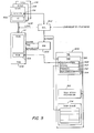
- FIG. 5 therein is represented the loading of an A/LU 218 into the system to become a Task 112, and the associated operations of S/L 302, TM 304 and MM 306. Shown therein are a plurality of A/LUs 218 resident in Disc 122, one of which is to be loaded into Memory 106 as a Task 112.
- the loading of an A/LU 218 into Memory is initiated by a request for such an operation.
- requests may be initiated by a user through KYBD 114 and Input 324, or may be initiated by another active Task 112, and will include a file name identification of the requested A/LU 218.
- Such a request is provided to S/L 302, which identifies the corresponding A/LU 218 by means of a Header 502, containing identification information, associated with the A/LU 218 Task Code (TC) 504, or routines.
- TC Task Code
- S/L 302 first generates a request to MM 306, by means of a M M 306 primitive (Getnode) , for an area of Memory 106 to be assigned as the TNS 308 of the requested A/LU 218/Task 112. MM 306 will respond by assigning such a space and will identify the location of the TNS 308 to S/L 302.
- the TNS 308 associated with a given Task 112 is effectively that Task 112s memory space to be used as required in executing its operations.
- S/L 302 then provides a request to TM 304 for TM 304 to construct the appropriate control structures for the requested A/LU 218.
- TM 304 responds by constructing a TCB 316, as described previously, and returning the TCB Identification (TCDI) 506 of the newly constructed TCB 316 associated with the requested A/LU 218.
- TCDI TCB Identification
- S/L 302 then writes the A/LU 218 into the assigned TNS 308 and the assigned TCDI 506 into an assigned location within the TNS 308.
- the A/LU 218 thereby becomes an executable Task 112 by being assigned an active TNS 308 and by being linked into TM 304 by its' associated TCDI 506, which is effectively an address, or pointer, to its' associated TCB 316 in TM 304.
- each TCB 316 includes a unique Identification 508 identifying that particular TCB 316, Status 510 information describing the state of execution of the associated Task 112, Priority 512 information identifying the relative priority of the associated Task 112, and a Task Stack Pointer 514 identifying the location of the associated Task 112s stack in TM 304's TSM 310.
- Each TCB 316 associated with a Task 112 effectively resides in TM 304's Task Queue 314 wherein the TCBs 316 are linked, or chained, in order of task execution by a series of head pointers and a tail pointer. The order of execution is determined by task priority and status and TM 304 maintains a separate Task Queue 314 for each level of priority.
- MM 306 provides means for a Task 112 to request the assignment of further Memory 106 space to its' TNS 308, specifically through the Getmynode primitive. Further description regarding the structure and operation of TM 304 and MM 306 may be found in the appendant articles titled, respectively, "Appendix A - Task Manager” and “Appendix B - Memory Manager", incorporated herein by reference.
- the structure of Document Files (DFs) 104 may be considered as comprised of two parts, the first being the actual document structure and the second being the file structure through which DM 318 accesses the document structure. These structures will thereby be described below, in that order and with reference to, respectively, Figs. 6 and 7.
- the concept upon which the document structure is based must first be described. Essentially, the concept of the document structure is based upon that of an actual, physical document, which is comprised of one or more pages and wherein each such page may be regarded as comprised of one or more definable areas, each area containing a particular type of information. The information which may appear in such areas may include, for example, single column text, multiple column text, graphics, images, headers or footers, and footnotes.
- a document file is comprised of a group of one or more Pages, wherein each Page is a rectangular, displayable object of general content comprised, for example, of text, graphic and image data.
- a Page may be a Menu, a Status line, a Prompt, or a Document Page.
- a Page should not be confused with a Document Page, which is one form of a Page.
- Each Page contains one or more Areas, an Area being a rectangular portion of a Page which is not sub-divided and which may contain one or more layers.
- a layer is a portion of the contents of an Area and contains a particular type of information, for example, text, graphics or images, and layers may be superimposed to comprise the contents of an Area.
- a Region is a rectangular portion of a Page which is further sub-divided.
- a Window is a rectangular portion of a Page which can be visible, for example to a user.
- a partial illustration of a DF 104 data structure is shown; the data structure is further illustrated in "Appendix C - Document Data Structure".
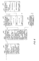
- the first element of the structure is a Page Block 602 containing a pointer to the first Area of the Page, Page size information, Page Cursor information describing the location of a cursor in the Page.
- the cursor position information defines the location within the Page wherein current operations, for example, the insertion of text, will be performed.
- the Page block also contain Path Pointer information pointing to a Path Block which in turn defines, for example, whether the Page contains graphic or free text information and areas to receive overflow text.
- the second element or elements of the data structure are one or more Area Blocks 604, each of which contains information pertaining to an associated Area of the Page.
- An Area Block 604 contains a pointer to the next Area Block 504, if there is more than one, information defining the type of Area, information identifying the locations of the top left and bottom right corners of the Area within the Page, and information regarding the right and left margins of the Area.
- a Text Contents pointer identifies the location of a Column Block 606, described below and identifying the location of text appearing in the Area, and a layer Descriptor identifies the location of a layer Block 608 described further below and identifying the location of graphics or image data appearing in the Area.
- Other fields of an Area Block 604 define the relationships between the edges of the Area and other Areas (ES), the path sequences to previous and next Areas of the Page (Path/Reference, Prev., Next), style information pertaining to text in the Area (Area Style), and information pertaining to positional characteristics of text appearing in the Area (VERTB1, HORTB1).
- the next elements, the C b lumn Blocks contain information pertaining to text appearing in the Area.
- the first information defines the number of lines appearing in a column of text and the vertical spacing of the lines.
- the Format Page field contains a pointer to a block of format information defining the format of the associated column.
- the following fields, Line 1, Line 2, and so on, contain pointers to Line Blocks 610, each containing text appearing in the associated column and information pertaining to that text.
- a Line Block 610 the text appearing in a column is comprised of a series of text strings, each such string having common characteristics, or attributes, such as whether the characters are bold or italic or overscored or underscored.
- a Line Block 610 is comprised of a Line Prefix String containing information pertaining to the following text and one or more Text Strings containing the characters of the text.
- Each Text String is comprised of a String Header containing information regarding the characteristics or attributes of the associated string of text characters, and a string of text characters to which those attributes apply.
- a line may also contain a reference to an external information item which applies or is related to the Line, for example, headers, footers and footnotes, but may include other such items.
- each Layer Block 608 contains a Graphics Descriptor or an Image Descriptor, each being a pointer to an associated body of graphics or image data appearing in the Area.
- the document file structure used by Dt4 318 included an Index Block 702 which includes a Text Page Index field 704 containing pointers identifying the locations of the Page Blocks 602 in the associated DF 104.
- a Page Block 602 of a DF 104 then contains the information necessary to locate the remaining information pertaining to that Page.
- the Index Block 702 further contains an Item Index field 706 identifying the locations of the Item File Blocks 708 in Item File 710.
- the Item File Blocks 708 of Item File 710 may be chained together in the same manner as described above with reference to the document data structure and Item File 710 contains information pertaining to headers, footers and footnotes appearing in the document contained in the associated document structure.
- Index Block 702 further contains a Named Item Index Field 712 which contains pointers identifying the locations of the Named Item Blocks 714 in Named Item File 716.
- Named Item Blocks 714 in Named Item File 716 may again be chained together in the manner described above and essentially contain document data which is identified specifically by names, for example, forms containing blank spaces to be filled in as, for example, described in E.P. Patent Application 85 100 013.3, titled “Electronic Processing With Forms” and filed Jan. 2 , 1985. Further description of the document file structure may be found in the appendant article titled “Appendix D - File Management System", incorporated herein by reference.
- DM 318 is illustrated with respect to the loading, or opening, of a DF 104 and subsequent access to such a DF 104 by a Task 112. Further information regarding DM 318 may be found in the appendant article titled “Appendix E - Document Manager” and is incorporated herein by reference.
- a single DF 230 in disc file format is to be selected from a plurality of such DF 230s in Disc 120 and is to be read into Memory 106 as a DF 104 in document structure format for subsequent access by a Task 112.
- the loading of a DF 230 into Memory 106 may be initiated by means of a request issued by a Task 112, either as a result of a user command to do so or as a result of the operation of the Task 112.
- the Task 112 desiring access to the document is shown as issuing the request.
- Such a request is essentially comprised of an open document request to the appropriate DM 318 OPEN routine, accompanied by the "Name", or file name, of the document requested.
- DM 318 responds to such a request by locating the requested document in Disc 120 through the DM File Structure (DMFS) 802 and by issuing to MM 106 a request for the assignment of Memory 106 space in which to write the requested DF 104.
- MM 106 will respond in the manner described previously with reference to the operation of S/L 302 and the requested DF 230 will be assigned Memory 106 space in which to be written in document structure format as a DF 104. The requested DF 104 will then be actually written into Memory 106 is a separate, subsequent operation.
- DMFS DM File Structure
- DCB Document Control Block
- DCB ADD DCB Address 804
- a DCB contains file information usable by DM 318 in maintaining the DF 104, information locating the document data within the DF 104 data structure, and information used by the Task 112 in operating upon the document data.
- the Task 112 submits a request for such an operation to the DM 318 ACCESS routines.
- a request is comprised of an identification of the access or operation desired, the DCB ADD 804 of the DCB 320 corresponding to the DF 104, and the location within the document structure to which access is desired.
- location information takes the form of the identification of the Page containing the location, and the location within the Page.
- the Task 112 has requested access to Page X of the DF 104.
- DM 318 then, using the access information contained in the corresponding DCB 320 and the document structure previously described with reference to Fig. 6, locates the location, or address, within Memory 106 of the requested Page X and returns this Memory Address (MEM ADD) 806 to a designated location in Task 112.
- Task 112 may then execute the desired operation.
- a DCB 320 is comprised to two major groups of information fields.
- the first, File Fields 902 is comprised of information used by DM 318 and DMFS 802 in maintaining the document record, or file, while the second group of fields, Document Fields 904, contains information used in accessing and operating upon the data contained in the DF 104 data structure.
- the contents and functions of the various fields comprising File Fields 902 are described in detail in the appendant article titled "Appendix D - File Management System" and, being incorporated herein by reference, will not be discussed further at this point.
- the contents and functions of the various fields comprising Document Fields 904 will be described further next below.
- Fig. 6, illustrating the document data structure, and to Appendix C - Document Data Structure.
- Document Fields 904 contain information used, in part, in accessing and operating upon the document data contained in the document structure and, in part, link a Task 112 operating upon such data to the data in the document structure.
- Field 906 Current Page Number
- Field 908 Current Offset
- DM 318 Current Offset
- Fields 910 and 912 respectively Next Offset To Read/Write Data, Last Offset to Read/Write Data, identify the locations of the previous and next Columns containing data which may be operated upon.
- Field 914 last Active Page
- Field 916 Next Area To Operate Upon
- Field 918 Current Format In Effect
- Field 932 Last Format
- Field 920 (Number Of Lines To Process) indicates the number of Lines in the Column currently being operated upon while Field 922 (Next Line To Process) identifies the next of those Lines.
- Field 924 (Lengths Of Blocks Used to Generate Offsets) identifies the lengths of the Blocks in the document.
- Field 926 (Pointer To Page Index For This Document) contains a pointer to the Text Page Index 704 of the Document File Structure (see Fig. 7).
- Field 930 (Pointer To Item Index For This Document) is similar to Field 928 but contains a pointer to Item Index 706.
- Field 928 (Pointer to Bitmap Block) contains a pointer to the Document File Structure field indicated the used/un-used Blocks in the document while Field 934 (Pointer to List of Blocks) similarly contains a pointer to a list of the Blocks in the document.
- SM Screen Manager
- SM 322 operates with R/BMDM 328, under control of Tasks 112 or user command through Input 324, to generate visual displays representing system operations or information, the resulting displays being presented to the user through DSP 118.
- SM 322 defines the information to be displayed, extracts the information from DFs 104 or TM 304, and provides the information to be displayed to R/BMDM 328.
- SM 322 is the only system element which is not required to access DFs 104 through DM 318, although SM 322 utilizes the document structures constructed by DM 318 to access document data for display.
- R/BMDM 328 is comprised of a rasterizer and a bit mapped display memory.
- the rasterizer portion of R/BMLM 328 receives information to be displayed from SM 322, rasterizes the information into bit mapped form, and stores the resulting bit mapped display information in the bit mapped memory portion of R/BMDM 328.
- the display information is then read from the bit mapped display memory and displayed to the user through DSP 118.
- the present system is a multi-tasking system, that is, can execute one task which interacts with the user in the foreground mode while executing one or more tasks not requiring such interaction in the background mode.
- the display provided by SM 322 reflects this system operation in the manner in which it generates a "windowed" display. That is, the screen display is divided into various windows, or areas, each window displaying information regarding a an associated aspect of system operation. As described below, the location, size and information content of each such window is dependent upon the associated aspect of system operation to be displayed therein.
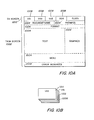
- FIG. 10A A typical display on the physical display screen of DSP 118 is illustrated in Fig. 10A.
- a display from the foreground task is provided on a major portion of the physical display screen indicated as the Task Screen 1002.
- the display on the task screen may be divided into a number of display Viewports 1004, each of which independently displays a different set of information.
- Viewports 1004 are shown separated by broken lines but such lines need not actually be displayed.
- Viewports 1004 are provided to display the document name, prompts, word processing page format, text, graphics, a user menu, and error messages.
- many other types of information can be displayed in different Viewports 1004 and all of the Viewports 1004 shown in Fig. 10A need not be displayed at any one time.
- the viewport technique gives each application task great flexibility in designating the data to be displayed. That flexibility is obtained with little added complication to the application task software because, once established by the application task, it is controlled by SM 322. Once the Viewports 1004 have been established, the application software need only be concerned with completing the task and modifying the data to be displayed as required by the task. As noted above, only the Task 112 with which the user is interacting at any time is permitted to control a display on the physical screen. Although background tasks are not permitted to control DSP 118, SM 322 establishes virtual screens corresponding to background applications.
- Those virtual screens can be considered, as shown in Fig. 10B, to be the logical equivalent of a stack of pages including Virtual Screens 1006 VS1, VS2, VS3 and VS4. Only one of those Virtual Screens 1006 is displayed on the physical screen, that is, as Task Screen 1002. The other Virtual Screens 1006 are held by SM 322 for display when called by the operator.
- SM 322 provides Virtual Screen Identifiers 1008 in a Virtual Screen portion 1010. Each Identifier 1008 may name the associated Virtual Screen 1006, or Task 112, and may also provide an indication as to the status of the associated Task 112.
- the SM 318 Virtual Screen portion 1010 may also include a calendar and clock display.
- the present system further offers windowing at two levels. The first is at the the task level wherein a Virtual Screen 1006 may be associated with a Task 112 and the Virtual Screen 1006 associated with the current foreground Task 112 associated with Task Screen 1002. SM 322 may create as many Virtual Screens 1006 as desired by the system user and may associated more than one Virtual Screen 1006 with a particular Task 112.
- the second level is within the task level, whereby a particular application Task l12 can subdivide its' associated Virtual Screen 1006 into viewport windows, each displaying different information regarding that particular Task 112.
- a Virtual Screen 1006 may be regarded as the visual display for its associated Task 112 and each viewport defined therein may be regarded as a logical display window looking onto a designated area of the document being operated upon the that Task 112.
- a Virtual Screen 1006 will contain at least one viewport, and may contain as many viewports as desired by the system user.
- Each viewport within a Virtual Screen 1006 may be individually defined as regards viewport size and position within the document and, in general, all viewports defined in a Virtual Screen 1006 will appear side by side in Task Screen 1002 whenever the associated Task 112 become the foreground task.
- DM 322 constructs a Virtual Screen Descriptor Block (VSDB) 1102 for each active Task 112, the VSDB 1102 acting, for each such Task 112, to link SM 322 to both the associated Task l12 and the DF 104 being operated upon by the Task 112.
- VSDB Virtual Screen Descriptor Block
- SM 322 will construct a VSDB 1102, and associated viewport descriptor blocks, described below, for each DF 104 being operated upon by the Task 112 with the Task 112 and SM 322 being linked to each such DF 104 through the associated VSDBs 1102.
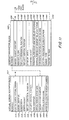
- each VSDB 1102 includes a Screen Identifier (SID) field 1104 identifying the particular Virtual Screen 1006, a Virtual Screen Name (VSN) field 1106 containing a name identification of the corresponding Virtual Screen 1006, and a Task Identifier (TID) field 1108 identifying the Task 112 associated with the corresponding Virtual Screen 1006.
- SID Screen Identifier
- VSN Virtual Screen Name
- TID Task Identifier
- PNVS Pointer To Next Virtual Screen
- SW Screen Width
- SH Screen Height
- TLHP Top Left Horizontal Position
- TLVP Top Left Vertical Position
- VDB Viewport Descriptor Block
- the VDB 1120 in turn being associated with the Virtual Screen 1006's VSDB 1102.
- the VSDB 1102 of a Virtual SCreen 1006 contains a Pointer to First Viewport field 1124, which contain a pointer to the VDB 1122 of the first viewport associated with that Virtual Screen 1006.
- the VSDB 1102 also contains an Array Of Allocated Viewport Numbers field (VPN) 1126, which contains entries identifying the viewports associated with the corresponding Virtual Screen 1006.
- VPN Array Of Allocated Viewport Numbers field
- each VDB 1122 contains a Pointer To Next Viewport field 1128 which identifies the location of the next viewport associated with the corresponding Virtual Screen 1006, thereby chaining together the VDB 1122's associated with a particular Virtual Screen 1006 for location by SM 322.
- the VDB 1122 further includes a Pointer To Page (PTP) field 1130 which identifies the location of the Page upon which the associated viewport is logically positioned.
- PTP Pointer To Page
- the Pointer to Page field 1130 pointer points to the first Page Block 602 of that Page, as previously described with reference to Fig. 6.
- the VDB 1122 further contains Top Left Horizontal Position (TLHP) 1132, Top left Vertical Position (TLVP) 1134, Viewport Width (VW) 1136 and Viewport Height (VH) 1138 fields describing the relative position and dimensions of the viewport in the associated Virtual Screen 1106.
- TLHP Top Left Horizontal Position
- TLVP Top left Vertical Position
- VW Viewport Width
- VH Viewport Height
- the VDB also contains a Horizontal Position Of Viewport Relative To Page (HPVRP) field 1140 and a Vertical Position Of Viewport Relative to Page (VPVRP) field 1142 which describe the relative logical position of the associated viewport upon the Page identified by Pointer To Page field 1130.
- HPVRP Horizontal Position Of Viewport Relative To Page
- VPVRP Vertical Position Of Viewport Relative to Page
- the information contained in the HPVRP 1140 and VPVRP 1142 fields, together with the information contained in the PTP field 1130, may be used by SM 322 to identify and locate the logical position, relative to the data contained therein, of the viewport within the DF 104 data structure being operated upon by the associated Task 112.
- SM 322 may located and identify the data logically contained within the associated viewport. SM 322 may thereby read the data so identified to R/BMDM 328 to be displayed in that area of Task Screen 1002 identified by the information contained in TLHP field 1132, TLVP field 1134, W field 1136 and VH field 1138.
- VDB 1122 includes Cursor Type (CT) field 1144, Horizontal Position Of Cursor On Page (HPCP) field 1146, and Vertical Position Of Cursor On Page (HPCP) field 1148.
- CT field 1144 contains information regarding an peration to be performed at the cursor location or the type of data or information involved or being operated upon.
- HPCP field 1146 and VPCP field 1148 describe the position of a cursor associated with the corresponding viewport and located in the associated Page and within the viewport area in that Page. This cursor is initially located in the upper left corner of the viewport, at the position defined by TLHP field 1132 and TLVP field 1134, and is moved about within the viewport as the associated Task 112 performs operations upon that portion of the data structure corresponding to the viewport area. The cursor essentially defines the location of the data currently being operated upon by the associated Task 112.
- the position of the cursor as defined by HPCP field 1146 and VPCP field 1148 is monitored with regard to the position and area of the viewport as defined by the other fields of the VCB 1122. If the Task l12 operations related to the cursor move outside of the viewport area defined by the VDB 1122 fields, the position of the viewport is moved accordingly by by SM 322 by writing new viewport position information into the appropriate VDB 1122 fields. The viewport associated with a Task 112 thereby remains logically located over the DF 104 data area in which the Task 112 is operating.
- VDB 1122 contains a Viewport Flag field 1150 containing flags describing the viewport to SM 322 and used by SM 322 in maintaining the viewport.
- the creation of a Virtual Screen 1006 or a viewport within an existng Virtual Screen 1006 is generally initiated by a Task 112 in response to a user request, which may be entered by means of input through KYBD 114 and Input 324.
- the Task 112 will respond by providing the appropriate request for the creation of a virtual screen or viewport (C VS/VP) to SM 322, the request including the identity of the requesting Task 112, the DCB ADD 804 referring to the DCB 320 of the DF 104 in which the virtual window or viewport is to appear, and information defining the virtual screen or viewport.
- C VS/VP virtual screen or viewport
- SM 322 will respond to such a request by creating the appropriate VSDB 1102 and a first VDB 1122, or if the request is for an additional viewport, by creating the appropriate VDB 1122.
- SM322 writes a Task Identifier into TID field 1108, providing a link back to the requesting Task 112, and a Pointer to First Viewport into PTFV field 1124 to link the VSDB 1102 to the associated VDB 1122.
- SM 322 writes a viewport number corresponding to the newly created viewport into VPN field 1126. A previously described, this field is used by SM 322 in maintaining and administering the allocated viewports.
- SM 322 writes a Virtual Screen Number 1202 back into a designated location in the Task 112 Task Node Space 308 to be used by the Task 112 in identifying the associated VSDB 1102.
- VDB 1122 will then, if the request was either for a new virtual screen or for new viewport within an existing virtual screen, create a VDB 1122 as described above. If the request was for a new virtual screen, the VDB 1122 will be the first VDB 1122 and is thereby pointed to by PTFV 1124. If the request was for an additional viewport, the new VDB 1122 will chained into the already existing chain of VDB 1122's by means of a pointer written into the PTNV field 1128 of the last previously existing VDB 1122. It should be noted that, in the creation of the VDB 1122, the DCB ADD provided with the initial request is used to create the Pointer to Page field 1130 entry in the VDB 1122.
- the cursor type and position fields of the VDB 1122 are similarly created at this time. Having created the necessary access structure, SM 322 will subsequently use the VSDB 1102 and associated VDBs 1122 to obtain and provide information to be displayed to R/BMDM 328 and DSP 118 whenever the associated Task 112 becomes the current foreground task.
Landscapes
- Engineering & Computer Science (AREA)
- Theoretical Computer Science (AREA)
- Physics & Mathematics (AREA)
- General Engineering & Computer Science (AREA)
- General Physics & Mathematics (AREA)
- Health & Medical Sciences (AREA)
- Artificial Intelligence (AREA)
- Audiology, Speech & Language Pathology (AREA)
- Computational Linguistics (AREA)
- General Health & Medical Sciences (AREA)
- Software Systems (AREA)
- Information Retrieval, Db Structures And Fs Structures Therefor (AREA)
Applications Claiming Priority (10)
| Application Number | Priority Date | Filing Date | Title |
|---|---|---|---|
| US65895384A | 1984-10-09 | 1984-10-09 | |
| US65919284A | 1984-10-09 | 1984-10-09 | |
| US06/658,951 US4658351A (en) | 1984-10-09 | 1984-10-09 | Task control means for a multi-tasking data processing system |
| US06/659,203 US4807142A (en) | 1984-10-09 | 1984-10-09 | Screen manager multiple viewport for a multi-tasking data processing system |
| US06/658,952 US4713754A (en) | 1984-10-09 | 1984-10-09 | Data structure for a document processing system |
| US658953 | 1984-10-09 | ||
| US659203 | 1984-10-09 | ||
| US659192 | 1984-10-09 | ||
| US658952 | 1984-10-09 | ||
| US658951 | 1984-10-09 |
Publications (1)
| Publication Number | Publication Date |
|---|---|
| EP0179350A2 true EP0179350A2 (fr) | 1986-04-30 |
Family
ID=27542046
Family Applications (1)
| Application Number | Title | Priority Date | Filing Date |
|---|---|---|---|
| EP85112744A Withdrawn EP0179350A2 (fr) | 1984-10-09 | 1985-10-08 | Système de traitement de données |
Country Status (2)
| Country | Link |
|---|---|
| EP (1) | EP0179350A2 (fr) |
| AU (1) | AU4717785A (fr) |
Cited By (2)
| Publication number | Priority date | Publication date | Assignee | Title |
|---|---|---|---|---|
| KR101284107B1 (ko) * | 2009-02-09 | 2013-07-10 | 퀄컴 인코포레이티드 | 다중캐리어 고속 업링크 패킷 액세스에서의 폐 루프 전력 제어 |
| KR101284103B1 (ko) * | 2009-02-09 | 2013-07-15 | 퀄컴 인코포레이티드 | 다중반송파 향상된 업링크에서의 전력 할당 |
-
1985
- 1985-09-09 AU AU47177/85A patent/AU4717785A/en not_active Abandoned
- 1985-10-08 EP EP85112744A patent/EP0179350A2/fr not_active Withdrawn
Cited By (2)
| Publication number | Priority date | Publication date | Assignee | Title |
|---|---|---|---|---|
| KR101284107B1 (ko) * | 2009-02-09 | 2013-07-10 | 퀄컴 인코포레이티드 | 다중캐리어 고속 업링크 패킷 액세스에서의 폐 루프 전력 제어 |
| KR101284103B1 (ko) * | 2009-02-09 | 2013-07-15 | 퀄컴 인코포레이티드 | 다중반송파 향상된 업링크에서의 전력 할당 |
Also Published As
| Publication number | Publication date |
|---|---|
| AU4717785A (en) | 1986-04-17 |
Similar Documents
| Publication | Publication Date | Title |
|---|---|---|
| US4713754A (en) | Data structure for a document processing system | |
| US4807142A (en) | Screen manager multiple viewport for a multi-tasking data processing system | |
| US4897780A (en) | Document manager system for allocating storage locations and generating corresponding control blocks for active documents in response to requests from active tasks | |
| US4658351A (en) | Task control means for a multi-tasking data processing system | |
| US4688167A (en) | Screen manager for data processing system | |
| US4633430A (en) | Control structure for a document processing system | |
| US6154756A (en) | Computer system integrating different data types into a single environment | |
| US5819283A (en) | Method and system for the extensibility of objects | |
| US4996662A (en) | Method for generating document using tables storing pointers and indexes | |
| US8230321B2 (en) | System in an electronic spreadsheet for displaying and/or hiding range of cells | |
| US8095867B2 (en) | System and computer program product for copying and pasting displayed elements of a range of cells in an electronic spreadsheet | |
| US4890257A (en) | Multiple window display system having indirectly addressable windows arranged in an ordered list | |
| EP0734552B1 (fr) | Systeme de securite de taches oriente objets | |
| US7275207B2 (en) | System and method in an electronic spreadsheet for displaying and/or hiding range of cells | |
| US7665017B2 (en) | Computer system integrating different data types into a single environment | |
| US5062039A (en) | Sharing of workspaces in interactive processing using workspace name tables for linking of workspaces | |
| US20030188258A1 (en) | System and method in an electronic spreadsheet for displaying and/or hiding range of cells | |
| JPH07182151A (ja) | 対応関係を用いた状態遷移モデルベースのソフトウェア入力・実行装置、及び、対応関係を用いた状態遷移モデルベースのソフトウェアの入力・実行方法 | |
| EP0179350A2 (fr) | Système de traitement de données | |
| CA1232077A (fr) | Dispositif de controle pour systeme de traitement de donnees | |
| Weck | A graphic system utilizing an associative data structure | |
| Anderson et al. | Design of a time-sharing system allowing interactive graphics | |
| Van Hoeve et al. | An object‐oriented approach to application generation | |
| Piattelli et al. | TERESA: a modular multiprocess software architecture for experimental nuclear data handling | |
| PETTERSSON | Application programming of real time displays |
Legal Events
| Date | Code | Title | Description |
|---|---|---|---|
| PUAI | Public reference made under article 153(3) epc to a published international application that has entered the european phase |
Free format text: ORIGINAL CODE: 0009012 |
|
| AK | Designated contracting states |
Kind code of ref document: A2 Designated state(s): BE DE FR GB |
|
| RIN1 | Information on inventor provided before grant (corrected) |
Inventor name: TENG, PETER Y. Inventor name: LAKNESS, DAVID R. Inventor name: KNAPP, SUZANNE C. Inventor name: AGARWAL, ARUN K. |
|
| STAA | Information on the status of an ep patent application or granted ep patent |
Free format text: STATUS: THE APPLICATION HAS BEEN WITHDRAWN |
|
| 18W | Application withdrawn |
Withdrawal date: 19871030 |
|
| RIN1 | Information on inventor provided before grant (corrected) |
Inventor name: TENG, PETER Y. Inventor name: LAKNESS, DAVID R. Inventor name: KNAPP, SUZANNE C. Inventor name: AGARWAL, ARUN K. |