EP0179366A2 - Méthode et système de commande pour surveiller l'introduction, dans un récipient, d'un gaz liquéfié sous pression - Google Patents
Méthode et système de commande pour surveiller l'introduction, dans un récipient, d'un gaz liquéfié sous pression Download PDFInfo
- Publication number
- EP0179366A2 EP0179366A2 EP85112915A EP85112915A EP0179366A2 EP 0179366 A2 EP0179366 A2 EP 0179366A2 EP 85112915 A EP85112915 A EP 85112915A EP 85112915 A EP85112915 A EP 85112915A EP 0179366 A2 EP0179366 A2 EP 0179366A2
- Authority
- EP
- European Patent Office
- Prior art keywords
- control system
- gas
- container
- signal
- valve
- Prior art date
- Legal status (The legal status is an assumption and is not a legal conclusion. Google has not performed a legal analysis and makes no representation as to the accuracy of the status listed.)
- Withdrawn
Links
Images


Classifications
-
- B—PERFORMING OPERATIONS; TRANSPORTING
- B65—CONVEYING; PACKING; STORING; HANDLING THIN OR FILAMENTARY MATERIAL
- B65B—MACHINES, APPARATUS OR DEVICES FOR, OR METHODS OF, PACKAGING ARTICLES OR MATERIALS; UNPACKING
- B65B31/00—Packaging articles or materials under special atmospheric or gaseous conditions; Adding propellants to aerosol containers
-
- B—PERFORMING OPERATIONS; TRANSPORTING
- B65—CONVEYING; PACKING; STORING; HANDLING THIN OR FILAMENTARY MATERIAL
- B65B—MACHINES, APPARATUS OR DEVICES FOR, OR METHODS OF, PACKAGING ARTICLES OR MATERIALS; UNPACKING
- B65B31/00—Packaging articles or materials under special atmospheric or gaseous conditions; Adding propellants to aerosol containers
- B65B31/006—Adding fluids for preventing deformation of filled and closed containers or wrappers
-
- F—MECHANICAL ENGINEERING; LIGHTING; HEATING; WEAPONS; BLASTING
- F17—STORING OR DISTRIBUTING GASES OR LIQUIDS
- F17C—VESSELS FOR CONTAINING OR STORING COMPRESSED, LIQUEFIED OR SOLIDIFIED GASES; FIXED-CAPACITY GAS-HOLDERS; FILLING VESSELS WITH, OR DISCHARGING FROM VESSELS, COMPRESSED, LIQUEFIED, OR SOLIDIFIED GASES
- F17C9/00—Methods or apparatus for discharging liquefied or solidified gases from vessels not under pressure
-
- F—MECHANICAL ENGINEERING; LIGHTING; HEATING; WEAPONS; BLASTING
- F17—STORING OR DISTRIBUTING GASES OR LIQUIDS
- F17C—VESSELS FOR CONTAINING OR STORING COMPRESSED, LIQUEFIED OR SOLIDIFIED GASES; FIXED-CAPACITY GAS-HOLDERS; FILLING VESSELS WITH, OR DISCHARGING FROM VESSELS, COMPRESSED, LIQUEFIED, OR SOLIDIFIED GASES
- F17C2205/00—Vessel construction, in particular mounting arrangements, attachments or identifications means
- F17C2205/03—Fluid connections, filters, valves, closure means or other attachments
- F17C2205/0302—Fittings, valves, filters, or components in connection with the gas storage device
- F17C2205/0323—Valves
- F17C2205/0326—Valves electrically actuated
-
- F—MECHANICAL ENGINEERING; LIGHTING; HEATING; WEAPONS; BLASTING
- F17—STORING OR DISTRIBUTING GASES OR LIQUIDS
- F17C—VESSELS FOR CONTAINING OR STORING COMPRESSED, LIQUEFIED OR SOLIDIFIED GASES; FIXED-CAPACITY GAS-HOLDERS; FILLING VESSELS WITH, OR DISCHARGING FROM VESSELS, COMPRESSED, LIQUEFIED, OR SOLIDIFIED GASES
- F17C2221/00—Handled fluid, in particular type of fluid
- F17C2221/01—Pure fluids
- F17C2221/014—Nitrogen
-
- F—MECHANICAL ENGINEERING; LIGHTING; HEATING; WEAPONS; BLASTING
- F17—STORING OR DISTRIBUTING GASES OR LIQUIDS
- F17C—VESSELS FOR CONTAINING OR STORING COMPRESSED, LIQUEFIED OR SOLIDIFIED GASES; FIXED-CAPACITY GAS-HOLDERS; FILLING VESSELS WITH, OR DISCHARGING FROM VESSELS, COMPRESSED, LIQUEFIED, OR SOLIDIFIED GASES
- F17C2223/00—Handled fluid before transfer, i.e. state of fluid when stored in the vessel or before transfer from the vessel
- F17C2223/01—Handled fluid before transfer, i.e. state of fluid when stored in the vessel or before transfer from the vessel characterised by the phase
- F17C2223/0146—Two-phase
- F17C2223/0153—Liquefied gas, e.g. LPG, GPL
- F17C2223/0161—Liquefied gas, e.g. LPG, GPL cryogenic, e.g. LNG, GNL, PLNG
-
- F—MECHANICAL ENGINEERING; LIGHTING; HEATING; WEAPONS; BLASTING
- F17—STORING OR DISTRIBUTING GASES OR LIQUIDS
- F17C—VESSELS FOR CONTAINING OR STORING COMPRESSED, LIQUEFIED OR SOLIDIFIED GASES; FIXED-CAPACITY GAS-HOLDERS; FILLING VESSELS WITH, OR DISCHARGING FROM VESSELS, COMPRESSED, LIQUEFIED, OR SOLIDIFIED GASES
- F17C2250/00—Accessories; Control means; Indicating, measuring or monitoring of parameters
- F17C2250/03—Control means
- F17C2250/032—Control means using computers
-
- F—MECHANICAL ENGINEERING; LIGHTING; HEATING; WEAPONS; BLASTING
- F17—STORING OR DISTRIBUTING GASES OR LIQUIDS
- F17C—VESSELS FOR CONTAINING OR STORING COMPRESSED, LIQUEFIED OR SOLIDIFIED GASES; FIXED-CAPACITY GAS-HOLDERS; FILLING VESSELS WITH, OR DISCHARGING FROM VESSELS, COMPRESSED, LIQUEFIED, OR SOLIDIFIED GASES
- F17C2250/00—Accessories; Control means; Indicating, measuring or monitoring of parameters
- F17C2250/04—Indicating or measuring of parameters as input values
- F17C2250/0404—Parameters indicated or measured
- F17C2250/0408—Level of content in the vessel
-
- F—MECHANICAL ENGINEERING; LIGHTING; HEATING; WEAPONS; BLASTING
- F17—STORING OR DISTRIBUTING GASES OR LIQUIDS
- F17C—VESSELS FOR CONTAINING OR STORING COMPRESSED, LIQUEFIED OR SOLIDIFIED GASES; FIXED-CAPACITY GAS-HOLDERS; FILLING VESSELS WITH, OR DISCHARGING FROM VESSELS, COMPRESSED, LIQUEFIED, OR SOLIDIFIED GASES
- F17C2250/00—Accessories; Control means; Indicating, measuring or monitoring of parameters
- F17C2250/04—Indicating or measuring of parameters as input values
- F17C2250/0404—Parameters indicated or measured
- F17C2250/043—Pressure
-
- F—MECHANICAL ENGINEERING; LIGHTING; HEATING; WEAPONS; BLASTING
- F17—STORING OR DISTRIBUTING GASES OR LIQUIDS
- F17C—VESSELS FOR CONTAINING OR STORING COMPRESSED, LIQUEFIED OR SOLIDIFIED GASES; FIXED-CAPACITY GAS-HOLDERS; FILLING VESSELS WITH, OR DISCHARGING FROM VESSELS, COMPRESSED, LIQUEFIED, OR SOLIDIFIED GASES
- F17C2250/00—Accessories; Control means; Indicating, measuring or monitoring of parameters
- F17C2250/04—Indicating or measuring of parameters as input values
- F17C2250/0404—Parameters indicated or measured
- F17C2250/0478—Position or presence
-
- F—MECHANICAL ENGINEERING; LIGHTING; HEATING; WEAPONS; BLASTING
- F17—STORING OR DISTRIBUTING GASES OR LIQUIDS
- F17C—VESSELS FOR CONTAINING OR STORING COMPRESSED, LIQUEFIED OR SOLIDIFIED GASES; FIXED-CAPACITY GAS-HOLDERS; FILLING VESSELS WITH, OR DISCHARGING FROM VESSELS, COMPRESSED, LIQUEFIED, OR SOLIDIFIED GASES
- F17C2250/00—Accessories; Control means; Indicating, measuring or monitoring of parameters
- F17C2250/06—Controlling or regulating of parameters as output values
- F17C2250/0605—Parameters
- F17C2250/0621—Volume
-
- F—MECHANICAL ENGINEERING; LIGHTING; HEATING; WEAPONS; BLASTING
- F17—STORING OR DISTRIBUTING GASES OR LIQUIDS
- F17C—VESSELS FOR CONTAINING OR STORING COMPRESSED, LIQUEFIED OR SOLIDIFIED GASES; FIXED-CAPACITY GAS-HOLDERS; FILLING VESSELS WITH, OR DISCHARGING FROM VESSELS, COMPRESSED, LIQUEFIED, OR SOLIDIFIED GASES
- F17C2250/00—Accessories; Control means; Indicating, measuring or monitoring of parameters
- F17C2250/06—Controlling or regulating of parameters as output values
- F17C2250/0605—Parameters
- F17C2250/0636—Flow or movement of content
-
- F—MECHANICAL ENGINEERING; LIGHTING; HEATING; WEAPONS; BLASTING
- F17—STORING OR DISTRIBUTING GASES OR LIQUIDS
- F17C—VESSELS FOR CONTAINING OR STORING COMPRESSED, LIQUEFIED OR SOLIDIFIED GASES; FIXED-CAPACITY GAS-HOLDERS; FILLING VESSELS WITH, OR DISCHARGING FROM VESSELS, COMPRESSED, LIQUEFIED, OR SOLIDIFIED GASES
- F17C2250/00—Accessories; Control means; Indicating, measuring or monitoring of parameters
- F17C2250/07—Actions triggered by measured parameters
- F17C2250/072—Action when predefined value is reached
-
- F—MECHANICAL ENGINEERING; LIGHTING; HEATING; WEAPONS; BLASTING
- F17—STORING OR DISTRIBUTING GASES OR LIQUIDS
- F17C—VESSELS FOR CONTAINING OR STORING COMPRESSED, LIQUEFIED OR SOLIDIFIED GASES; FIXED-CAPACITY GAS-HOLDERS; FILLING VESSELS WITH, OR DISCHARGING FROM VESSELS, COMPRESSED, LIQUEFIED, OR SOLIDIFIED GASES
- F17C2260/00—Purposes of gas storage and gas handling
- F17C2260/02—Improving properties related to fluid or fluid transfer
- F17C2260/024—Improving metering
-
- F—MECHANICAL ENGINEERING; LIGHTING; HEATING; WEAPONS; BLASTING
- F17—STORING OR DISTRIBUTING GASES OR LIQUIDS
- F17C—VESSELS FOR CONTAINING OR STORING COMPRESSED, LIQUEFIED OR SOLIDIFIED GASES; FIXED-CAPACITY GAS-HOLDERS; FILLING VESSELS WITH, OR DISCHARGING FROM VESSELS, COMPRESSED, LIQUEFIED, OR SOLIDIFIED GASES
- F17C2260/00—Purposes of gas storage and gas handling
- F17C2260/04—Reducing risks and environmental impact
- F17C2260/042—Reducing risk of explosion
-
- F—MECHANICAL ENGINEERING; LIGHTING; HEATING; WEAPONS; BLASTING
- F17—STORING OR DISTRIBUTING GASES OR LIQUIDS
- F17C—VESSELS FOR CONTAINING OR STORING COMPRESSED, LIQUEFIED OR SOLIDIFIED GASES; FIXED-CAPACITY GAS-HOLDERS; FILLING VESSELS WITH, OR DISCHARGING FROM VESSELS, COMPRESSED, LIQUEFIED, OR SOLIDIFIED GASES
- F17C2270/00—Applications
- F17C2270/05—Applications for industrial use
- F17C2270/059—Mass bottling, e.g. merry belts
Definitions
- the invention relates generally to the generation of internal pressure in containers and, more particularly, to a control system and control method for controlling the volume of a liquid inert gas that is dispensed into a container to ensure the desired internal pressure in the container after it has been closed.
- a system is known under the trademark TapTone-System (cf. US-PS 38 02 252) to check containers and to determine the extent of the internal pressure of such containers.
- This system can either be based on the profile of the lid in the case of a can, or operate on the sound emitted from the container when the lid is depressed and released.
- the present invention is based on this known system.
- this system not only is it determined whether the pressure within a container is within predetermined limits, but the system can also control the discharge of those containers which have an internal pressure which is too low or too high.
- the system converts the sound emitted by the container into pressure areas, generating separate and different signals for each pressure area. Furthermore, switching means are selectively switched on by the different pressure range signals in order to trigger the ejection device for the container.
- the signals indicating different pressures can also be directed to a recorder which records a running record of the pressure displayed within each container or can being tested.
- Devices have also been developed to control controlled amounts of liquid inert gas, such as hydrogen, in a filled container prior to closing the container to ensure a predetermined internal pressure in the container due to evaporation of the liquid inert gas.
- Pressure detectors and indicators are used downstream of the LPG dispensers to determine whether the correct amount of liquid hydrogen, for example, has been introduced into the container.
- the invention relates to the system described in more detail at the outset and aims to introduce the liquefied gas into the container in a much more economical and precise manner, so that the proportion of containers to be separated out is considerably lower than before.
- control signals obtained in the known control system and derived from pressure data are converted into a control for the valve for dispensing the liquid gas, so that the time during which this valve is open is automatically varied. This results in a precise control of the amount of liquid nitrogen or other inert gas.
- the required amount is derived from the mean pressure values that are determined in relation to the containers examined.
- the control system receives exponential data from the known control system and averages this data every time a container is checked. This provides digital average information which is then converted into an analog output signal. This is featured with a selected set point compared to obtain a control pulse with a width corresponding to that required by the analog output signal. The length of this pulse controls the time during which the valve opens and thus the volume of liquid gas released, such as nitrogen.
- a detector is provided in connection with the gas dispenser, which provides a control signal generated, which corresponds to its length of time according to the time during which a container is in a position to receive the liquid gas emitted.
- This additional pulse is used in conjunction with the valve opening pulse in series so that the container detector functions as a no container / dispensing control and as a final control of the dispensing to prevent liquid nitrogen from being dispensed. after the container has moved too far.
- a new dispensing device for liquid for example liquid nitrogen
- This dispenser has a novel valve, in which escaping gas vapor is advantageously used to shield the working components of the dispensing device against moisture containing air, so as to prevent the device from icing up.
- the device 10 shown in FIG. 1 for filling a container with a product, for introducing a liquefied gas, such as nitrogen, into the head space above the product, for closing the container and for testing the closed container with regard to the internal pressure that corresponds Has stations.
- the arrangement thus shows a filling station 12, a dispensing device 14 for liquid gas, a conventional container closing machine 16, a removal conveyor 18, and a test station 20 for determining the internal pressure.
- the container is a can C, the upper end of which is open and which is closed in the closing machine 16 by the use of a lid which is hermetically connected to the container body to produce a double seam.
- the filling station 12 and the dispensing station 14 for liquid gas are arranged in alignment one behind the other and are assigned to a common conveyor belt 22 which conveys the cans from the input end "a" into the closing machine, the cans C being arranged on the conveyor belt at uniform intervals.
- the cans C are filled with the desired product using a conventional filling device 24. In many cases this is in the canned product is a hot product.
- the cans After the cans have been filled, they will pass under the dispenser 26 for a liquefied gas, such as nitrogen, on the conveyor 22.
- a liquefied gas such as nitrogen
- the dispenser is controlled in timing with the placement of a can beneath the dispenser 26, with the amount of liquefied gas dispensed being closely monitored in a manner described below.
- the cans enter the closing machine 16 and are hermetically sealed.
- the closed cans then leave the sealing machine 16 and arrive on the conveyor belt 28 of the removal device 18.
- the internal pressure of the closed cans is tested and determined by a pressure detector and a pressure indicator, which belong to the monitoring station 20. The distance is chosen so that there is sufficient time for the liquid gas to evaporate completely within the closed container, so. that normal pressure conditions have arisen which are still maintained within the closed container.
- the pressure monitoring station corresponds to the system described at the beginning. However, in accordance with the invention, a feedback signal is passed from the unit 20 to a control device 30 which controls the liquid gas dispenser 26.
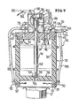
- the dispensing device 26 for liquid gas comprises a liquid gas tank 32, which preferably consists of a foamed plastic material, since it has sufficient surface tightness to prevent the liquid gas from flowing out.
- the tank 32 has a cylindrical body 34 with a bottom wall 36.
- the fuselage 34 preferably has a downwardly projecting apron section 37 which extends downward beyond the bottom wall 36.
- the tank 34 further includes an upper lid 38 with a centrally hanging plug portion 40 which engages tightly in the fuselage opening 34 and seals the upper end of the tank.
- the lid 38 is connected to the fuselage 34 by means of relatively weak screws 42, which form a predetermined breaking point when undesirable pressures arise within the tank 32, so that a tank explosion is prevented in this way.
- the tank 32 is filled with liquid nitrogen or an equivalent inert liquid gas up to a predetermined liquid level, through which a sufficient head space for vaporized gas remains in the tank 32 above the liquid.
- the tank 32 is provided with a filling device 44 which is carried by the cover 38 and is open into the tank via a filling channel 46.
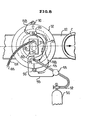
- the liquid gas reaches the filling device 44 via a feed line 46 (FIG. 8), the flow being controlled by a valve 48.
- the liquefied gas reaches the valve 48 from a supply 50 via the feed line 52.
- a fill level monitoring device 54 protrudes into the tank 32 from the cover 38 and has a control line 56 which is led to the valve 48 in order to ensure an automatic closing of the valve 48 when the liquid level of the liquid gas in the tank 32 reaches the desired level.
- the valve mainly includes a large diameter bore 58 on the underside of the bottom 36 which extends only partially through the bottom 36.
- the large bore 58 communicates with the interior of the tank 32 via a flow channel, which is generally formed by a conical valve seat 60.
- a movable valve member 62 is provided in the form of an elongated plastic rod, the lower end of which carries a generally conical valve member 64 which mates with and cooperates with the valve seat 60 to normally close the passage from the interior of the tank 32 into the bore 58 shut down.
- valve member 62 extends through a sleeve 66 of the cover 38 and projects into the lower end of a housing 68 in which an electromagnetic winding 70 is arranged.
- the upper end of the valve member 62 is provided with a metal extension 72 which projects into the winding 70 as an armature core.
- a metal sleeve 74 can be provided, which, however, only acts as a weight to force the rod downward into the closed position.
- a spring 76 can also be provided which constantly biases the valve member 62 downward.
- the electromagnetic coil 70 when the electromagnetic coil 70 is turned on, the armature 72 is pulled up to a central position in the coil 70 so that the valve element 64 is released from the valve seat 60 and the liquid nitrogen exits through the bottom of the tank enables.
- the amount of LPG specified each time the valve is opened depends mainly on the opening time of the valve.
- an adjustment device for the adjustment of the valve element 64 relative to the valve seat 60 can be provided, e.g. by vertically adjusting the winding 70.
- a mounting plate 78 for the electromagnetic winding 70 is suspended from an upper wall of the housing 68 by means of threaded support elements 80 which protrude through a nut or similar element 82 which in turn passes through the Support plate 78 are worn.
- a spring 84 surrounds the fastener 80 so that the electromagnetic winding is fixed in each position.
- the feed line 46 is surrounded by a corresponding cladding tube 86 or the like.
- Steam lines 88 are also connected to fittings 90 carried by the skirt portion 36 to direct the steam into the area under the floor 36 into the space surrounding the skirt portion through holes 92 in the skirt portion.
- the cover 38 is provided with a gas vent hole 94, which is provided with a connector 96 outside the cover. To these lines 88 and 98 are coupled, which steam supplies the connector 100 and the pipe jacket 86.
- the tank 32 is mounted above the conveyor belt 22 with the aid of a corresponding support device 108, which is carried by the holder 110. It can also be seen that the support 108 carries a holder 112, on which a proximity sensor 114 is provided, which detects when a can C has reached a control position below the tank 32.
- control device 30 is arranged in a corresponding housing 116 which is mounted near the tank 32 and the proximity sensor 114.
- Control lines 106 for the winding 70 lead to the housing 116.
- Further control lines 118 lead to the proximity sensor 114.
- a feed line 120 and control lines 122 are provided, which lead to the control unit 20 of the known control system.
- the unit 20, i.e. the pressure sensor and indicator comprises a fastening device 124, by which a test head 126 is held in a position overlying the conveyor belt 28.
- the test head 126 uses induced magnetic forces to exert a downward force on the can lid in order to bend it down. If this force is suddenly interrupted, the can lid can jump out again with an audible click.
- the tone of this click is an indication of the amount of internal pressure inside the can.
- the unit 20 generates a signal as a function of the determined pressure with the aid of a control device arranged in a housing 128.
- the control device in the housing 128 is connected to a voltage source by line g.
- each signal differing from the adjacent signal corresponding to a pressure difference of, for example, 0.35 kg / cm 2 .
- a display panel 130 of the unit 128 is shown, on which a plurality of display lamps 132 are provided. Each indicator lamp is assigned to one of the ten detectable pressure ranges. Each lamp 132 is associated with a control switch 134 which can be selectively closed in order to connect the pressure indication signal to an ejection device 136 according to FIG. 1, which ejects cans C whose pressure is below or above a preselected standard. If, for example, the internal pressure in a tested can is below a pressure of 0.70 kg / cm 2 or above a pressure of 3.16 kg / cm 2 , this can can be expelled from the transport line as faulty. This is achieved by closing switch 134 via test circuits 1, 2 and 10.
- the pressure test data is used to control the length of time that the LPG discharge valve is open, thereby controlling the volume of the quantity of LPG discharged from the tank 32.
- a new control system 138 receives the pressure test data from the unit 20. These signals pass into an acceptable data filter 140 which filters out erroneous data and feeds well-found data 142 in exponential form to a unit 144 which averages and stores the exponential data and which generates a continuous signal that averages the data indicates that are received by the unit 20. For example, one test result may be 6, the next 5, then 6, then 7, and the like with an average of these test results in the range of 6. Units 140 and 144 together form a data logger "d".
- the average data is then fed to a memory circuit and a DC / AC converter 146, which converts the digital average signal into an analog output signal.
- the analog output signal is continuously fed to a control system "e", which has a comparator 148 to which an adjustable setting point 150 is assigned. In the example shown, this would be set to size "6".
- the output of comparator 48 is then fed to an analog / pulse width converter 152, the length of which is varied inversely in proportion to the difference in the compared data. For example, if the internal pressure for a can C is to be an average of 6 and the average date is 7, the pulse rate will decrease while if the average date is 5, the pulse width would increase. As shown below, the pulse width, which is the output of transducer 152, will control the length of time that the valve of dispenser 26 is open.
- the previously described proximity sensor 114 shown in FIG. 2 as a container response detector, also generates a control signal and the control signals from transducer 152 and container detector 114 are in series and provide a signal 154 to winding 10, around them To effect switching on, and that for a predetermined selected period of time.
- the container detector 114 generates a pulse P1 that has a constant predetermined length. Pulse P1 determines the length of time that a can of Cin can be in alignment with tank 32 to receive liquefied petroleum gas from the tank. Thus, the pulse P1 controls the time during which the valve of the tank 32 can be opened if a can is located below the valve.
- the pulse P1 has a trailing edge 158 which determines the point in time at which the dispensing of the liquid nitrogen into a container C underneath must be interrupted in order to ensure that the dispensed liquid gas also gets fully into the can.
- the pulse P2 is timed so that its trailing edge 160 coincides with the trailing edge 158 of the pulse P1, so that the discharge of the liquid gas is always interrupted at the point in time which is determined by the pulse P1.
- the pulse P1 is always longer in length than the pulse P2 and has a starting edge 162 which is assigned to a point in time at which the dispensing process for the liquid nitrogen can begin.
- the width of the pulse P2, as determined above, is controlled in accordance with the test results by the unit 20 so as to ensure delivery of the liquefied gas with a volume which provides the desired internal pressure within the can.
- the start edge 164 of pulse P2 will vary, but will always fall within the width of pulse P1.
- the winding 70 is only switched on when both pulses P1 and P2 are active. If a socket is thus not detected by the proximity sensor 114, the pulse P1 remains. Even if the pulse P2 requests the winding / 0 to be switched on, this switching cannot take place, so that the pulse P1 acts as a control in the sense: no D 1 se / no delivery.
- a liquid gas such as liquid nitrogen
- the product to be packaged is a hot fill product
- the air present in the head space above the product is heated at the time the can is closed. When the heated air is on Cooling down to room temperature results in a vacuum. Cans that are normally used cannot currently withstand this vacuum. It is therefore necessary to provide means to provide the can with an internal pressure to compensate for this vacuum effect.
- liquid nitrogen or the like is to make it possible to use thinner metals in the manufacture of such cans, especially for the can bodies. If a can is pressurized on the inside, it has greater stack strength by partially supporting the can body by the internal pressure. This allows the use of lighter sheet thicknesses for the manufacture of can bodies.
Landscapes
- Engineering & Computer Science (AREA)
- Mechanical Engineering (AREA)
- Chemical & Material Sciences (AREA)
- Dispersion Chemistry (AREA)
- General Engineering & Computer Science (AREA)
- Vacuum Packaging (AREA)
- Filling Or Discharging Of Gas Storage Vessels (AREA)
- Control Of Fluid Pressure (AREA)
Applications Claiming Priority (2)
| Application Number | Priority Date | Filing Date | Title |
|---|---|---|---|
| US660614 | 1984-10-12 | ||
| US06/660,614 US4662154A (en) | 1984-10-12 | 1984-10-12 | Liquid inert gas dispenser and control |
Publications (2)
| Publication Number | Publication Date |
|---|---|
| EP0179366A2 true EP0179366A2 (fr) | 1986-04-30 |
| EP0179366A3 EP0179366A3 (fr) | 1987-08-19 |
Family
ID=24650237
Family Applications (1)
| Application Number | Title | Priority Date | Filing Date |
|---|---|---|---|
| EP85112915A Withdrawn EP0179366A3 (fr) | 1984-10-12 | 1985-10-11 | Méthode et système de commande pour surveiller l'introduction, dans un récipient, d'un gaz liquéfié sous pression |
Country Status (3)
| Country | Link |
|---|---|
| US (1) | US4662154A (fr) |
| EP (1) | EP0179366A3 (fr) |
| JP (1) | JPS6197719A (fr) |
Cited By (3)
| Publication number | Priority date | Publication date | Assignee | Title |
|---|---|---|---|---|
| EP0413172A1 (fr) * | 1989-08-17 | 1991-02-20 | Robert Bosch Gmbh | Procédé de régulation d'une pression à l'aide d'une soupape magnétique. |
| EP0421597A1 (fr) * | 1989-09-04 | 1991-04-10 | ARTHUR GUINNESS SON & COMPANY (DUBLIN) LIMITED | Système de distribution de liquide et dispositif d'emballage comprenant le système |
| CN109051103A (zh) * | 2018-06-28 | 2018-12-21 | 苏州优康网络电子商务有限公司 | 一种基于等离子体的食品加工包装系统 |
Families Citing this family (29)
| Publication number | Priority date | Publication date | Assignee | Title |
|---|---|---|---|---|
| SE457750B (sv) * | 1986-07-21 | 1989-01-23 | Aga Ab | Apparat foer dosering av smaa maengder kondenserad gas |
| DE3625081A1 (de) * | 1986-07-24 | 1988-02-04 | Lieder Maschinenbau Gmbh & Co | Verfahren und vorrichtung zur konservierung von in einem behaelter eingeschlossener ware |
| US4865088A (en) * | 1986-09-29 | 1989-09-12 | Vacuum Barrier Corporation | Controller cryogenic liquid delivery |
| DE3638601A1 (de) * | 1986-11-12 | 1988-05-26 | Seitz Enzinger Noll Masch | Aufschaeumvorrichtung zum verdraengen des restluftvolumens aus mit einem aufschaeumbaren fluessigen fuellgut gefuellten behaeltern, insbesondere flaschen |
| JP2601649B2 (ja) * | 1986-12-10 | 1997-04-16 | 大和製衡 株式会社 | 金属検出器付き計量包装装置 |
| NL8603176A (nl) * | 1986-12-12 | 1988-07-01 | Calumatic Bv | Werkwijze en inrichting voor het verlagen van de hoeveelheid zuurstof in de ruimte boven de vulling binnen een houder. |
| US4947650A (en) * | 1989-09-08 | 1990-08-14 | Vacuum Barrier Corporation | Method and apparatus for liquid cryogen pressurization of containers of particulates |
| US5033254A (en) * | 1990-04-19 | 1991-07-23 | American National Can Company | Head-space calibrated liquified gas dispensing system |
| US5251424A (en) * | 1991-01-11 | 1993-10-12 | American National Can Company | Method of packaging products in plastic containers |
| FR2696152B1 (fr) * | 1992-09-29 | 1994-10-28 | Air Liquide | Procédé et dispositif de distribution de doses de liquide, notamment de gaz liquéfié. |
| GB9309637D0 (en) * | 1993-05-11 | 1993-06-23 | Boc Group Plc | Cryogenic liquid dispensers |
| US5385025A (en) * | 1994-03-04 | 1995-01-31 | Mg Industries | Apparatus and method for dispensing droplets of a cryogenic liquid |
| DE19502452A1 (de) * | 1995-01-26 | 1996-08-01 | Kronseder Maschf Krones | Verfahren und Vorrichtung zum Behandeln von Gefäßen |
| FR2736041B1 (fr) * | 1995-06-30 | 1997-08-29 | Deep | Procede de remplissage de bouteille, notamment en matiere plastique, avec un liquide et dispositif associe |
| US5846621A (en) * | 1995-09-15 | 1998-12-08 | Minnesota Mining And Manufacturing Company | Component carrier tape having static dissipative properties |
| DE19538216A1 (de) * | 1995-10-13 | 1997-04-17 | Schmalbach Lubeca | Verfahren zum Herstellen von mit Bier befüllten Dosen |
| US6523328B1 (en) * | 1999-09-13 | 2003-02-25 | Gilbert L. De Cardenas | System and apparatus for an automated container filling production line |
| US6393802B1 (en) | 1999-12-22 | 2002-05-28 | Sunrise Medical Hhg, Inc. | Cylinder filler for use with an oxygen concentrator |
| NZ521694A (en) | 2002-09-30 | 2005-05-27 | Co2 Pac Ltd | Container structure for removal of vacuum pressure |
| US6502369B1 (en) | 2000-10-25 | 2003-01-07 | Amcor Twinpak-North America Inc. | Method of supporting plastic containers during product filling and packaging when exposed to elevated temperatures and internal pressure variations |
| WO2005047760A2 (fr) * | 2003-11-10 | 2005-05-26 | Inflate, Llc | Procede et dispositif pour mettre en pression des contenants |
| US7717294B2 (en) | 2005-06-20 | 2010-05-18 | South-Tek Systems | Beverage dispensing gas consumption detection with alarm and backup operation |
| US7780025B2 (en) * | 2005-11-14 | 2010-08-24 | Graham Packaging Company, L.P. | Plastic container base structure and method for hot filling a plastic container |
| DE102007016159B4 (de) * | 2007-04-02 | 2018-11-22 | Khs Corpoplast Gmbh | Verfahren und Vorrichtung zum sterilen Abfüllen |
| TWI472459B (zh) | 2008-05-19 | 2015-02-11 | Melrose David | 移除真空壓力之頂部空間改性方法及其裝置 |
| US8365946B2 (en) | 2008-11-20 | 2013-02-05 | Inoflate, Llc | Device with expandable chamber for pressurizing containers |
| US9051098B2 (en) * | 2009-10-19 | 2015-06-09 | Inoflate, Llc | Method for pressurizing containers with nitrogen |
| CN104843226A (zh) * | 2015-04-10 | 2015-08-19 | 刘佳 | 用于谷物生产线的谷物包装方法及设备 |
| CN115363017B (zh) * | 2022-08-29 | 2025-11-28 | 浙江绿蔻生物技术有限公司 | 一种液氮梯度降温仪 |
Family Cites Families (14)
| Publication number | Priority date | Publication date | Assignee | Title |
|---|---|---|---|---|
| GB690324A (en) * | 1951-11-01 | 1953-04-15 | Pneumatic Scale Corp | A volumetric filling machine |
| US3515860A (en) * | 1967-11-06 | 1970-06-02 | Industrial Nucleonics Corp | Process controller with dynamic set-point adjustment responsive to the statistical variance of the controlled property |
| DE2162448A1 (de) * | 1971-12-16 | 1973-06-20 | Hesser Ag Maschf | Verpackungsanlage, die mehrere, mit fernsteuerbaren verstelleinrichtungen versehene abmessgeraete aufweist |
| US3802252A (en) * | 1972-06-09 | 1974-04-09 | Benthos Inc | Pressure and vacuum monitoring apparatus |
| US3881095A (en) * | 1973-04-03 | 1975-04-29 | Velcon Filters | System for evaluating sailboat performance |
| JPS53125095A (en) * | 1977-04-08 | 1978-11-01 | Oki Electric Ind Co Ltd | Airtightness detector of hermetic vessels |
| US4162689A (en) * | 1977-07-14 | 1979-07-31 | Hoffmann-La Roche Inc. | Time division flow control |
| US4316490A (en) * | 1979-10-02 | 1982-02-23 | Meyer Jerome K | Ice cream making and packaging system and method |
| US4320463A (en) * | 1980-02-25 | 1982-03-16 | S. Himmelstein And Company | Production control system |
| GB2089191B (en) * | 1980-12-10 | 1985-03-20 | Toyo Seikan Kaisha Ltd | Method and apparatus for making a hermetically sealed food container |
| US4407340A (en) * | 1980-12-18 | 1983-10-04 | Reynolds Metals Company | Container pressurization system |
| US4489767A (en) * | 1981-09-08 | 1984-12-25 | Toyo Seikan Kaisha, Ltd. | Apparatus for dropping liquefied gases |
| JPS58137698A (ja) * | 1981-11-11 | 1983-08-16 | Hokkai Can Co Ltd | 液化ガス定量注入装置 |
| US4494582A (en) * | 1983-04-05 | 1985-01-22 | Safeway Stores, Incorporated | Ice cream making and packaging system and method |
-
1984
- 1984-10-12 US US06/660,614 patent/US4662154A/en not_active Expired - Fee Related
-
1985
- 1985-10-11 JP JP60226653A patent/JPS6197719A/ja active Granted
- 1985-10-11 EP EP85112915A patent/EP0179366A3/fr not_active Withdrawn
Cited By (3)
| Publication number | Priority date | Publication date | Assignee | Title |
|---|---|---|---|---|
| EP0413172A1 (fr) * | 1989-08-17 | 1991-02-20 | Robert Bosch Gmbh | Procédé de régulation d'une pression à l'aide d'une soupape magnétique. |
| EP0421597A1 (fr) * | 1989-09-04 | 1991-04-10 | ARTHUR GUINNESS SON & COMPANY (DUBLIN) LIMITED | Système de distribution de liquide et dispositif d'emballage comprenant le système |
| CN109051103A (zh) * | 2018-06-28 | 2018-12-21 | 苏州优康网络电子商务有限公司 | 一种基于等离子体的食品加工包装系统 |
Also Published As
| Publication number | Publication date |
|---|---|
| EP0179366A3 (fr) | 1987-08-19 |
| JPS6197719A (ja) | 1986-05-16 |
| US4662154A (en) | 1987-05-05 |
| JPH0448243B2 (fr) | 1992-08-06 |
Similar Documents
| Publication | Publication Date | Title |
|---|---|---|
| EP0179366A2 (fr) | Méthode et système de commande pour surveiller l'introduction, dans un récipient, d'un gaz liquéfié sous pression | |
| DE1548199C3 (de) | Elektrische Einrichtung zum berührungsfreien Prüfen des Vakuumzustandes von verschlossenen Verpackungsbehältern | |
| CH691476A5 (de) | Vorrichtung zum Füllen einer Kanne mit Faserband. | |
| EP3108968A1 (fr) | Dispositif de determination du niveau de colle fondue dans un recipient | |
| DE69301887T2 (de) | Verfahren und Apparat zur dosierten Abgabe von Flüssigkeiten, insbesondere von Flüssiggas | |
| EP0483191B1 (fr) | Procede et dispositif pour commander et reguler la vitesse de remplissage du moule et la pression de coulee d'une machine de coulee en coquille a basse pression | |
| DE2616430A1 (de) | Verfahren und vorrichtung zum austreiben von schuettgut aus einem innendruckbelastbaren silobehaelter | |
| EP0425866A2 (fr) | Procédé et dispositif pour déposer de petites quantités d'une masse pâteuse sur une plaque de circuit | |
| DE3903768C2 (de) | Verfahren zum Füllen von Behältern, insbesondere Flaschen, mit einem vorzugsweise unter Umgebungsdruck stehenden flüssigen Füllgut sowie Füllmaschine zum Durchführen dieses Verfahrens | |
| DE69101052T2 (de) | Verfahren zum Abfüllen nicht mischbarer Flüssigkeiten in Fässer und dessen Anwendungen, insbesondere für die Abfüllung von weissem Phosphor. | |
| DE1558161A1 (de) | Ofen zum Beliefern einer oder mehrerer Giessvorrichtungen mit verschiedenen Mengen geschmolzenen Metalls | |
| EP1342505B1 (fr) | Dispositif pour le revêtement en poudre des objets | |
| DE3629074A1 (de) | Tabakschleuse | |
| CH631560A5 (en) | Metering device for liquids | |
| DE1698110B2 (de) | Pruefgeraet fuer die vakuumpruefung von behaeltern | |
| EP2105207B1 (fr) | Récipient pour produits pulvérulents, dispositif de transport de produits pulvérulents et procédé d'exploitation de celui-ci | |
| DE69206664T2 (de) | Automatische Anlage zum Fördern und Wiegen von mit einer radioaktiven Flüssigkeit gefüllten Flaschen zwischen einer Entnahmevorrichtung und einer Analysevorrichtung | |
| DE2053573A1 (de) | Verfahren zum automatischen Steuern der Atmosphäre in einem abgeschlossenen Speicher und Vorrichtung insbesondere zur Durchfuhrung des Verfahrens | |
| EP0271031A2 (fr) | Dispositif pour doser des gaz liquéfiés à bas point d'ébullition | |
| DE1598996B2 (de) | Einrichtung zum automatischen vergleich der oktanzahl eines pruefkraftstoffes mit derjenigen eines bezugskraftstoffes | |
| DE4007430A1 (de) | Verfahren zum foerdern von portionen aus koernigem oder pulvrigem schuettgut sowie vorrichtung zur durchfuehrung des verfahrens | |
| DE3801651C2 (fr) | ||
| EP0053322B1 (fr) | Dispositif de prise d'échantillons représentatifs d'huile brute | |
| DE3039608C2 (fr) | ||
| DE9106949U1 (de) | Einrichtung zum Abpacken von Flüssigkeiten in Behälter mittels eines Füllrüssels |
Legal Events
| Date | Code | Title | Description |
|---|---|---|---|
| PUAI | Public reference made under article 153(3) epc to a published international application that has entered the european phase |
Free format text: ORIGINAL CODE: 0009012 |
|
| AK | Designated contracting states |
Kind code of ref document: A2 Designated state(s): AT CH DE LI |
|
| PUAL | Search report despatched |
Free format text: ORIGINAL CODE: 0009013 |
|
| AK | Designated contracting states |
Kind code of ref document: A3 Designated state(s): AT CH DE LI |
|
| STAA | Information on the status of an ep patent application or granted ep patent |
Free format text: STATUS: THE APPLICATION IS DEEMED TO BE WITHDRAWN |
|
| 18D | Application deemed to be withdrawn |
Effective date: 19880219 |
|
| RIN1 | Information on inventor provided before grant (corrected) |
Inventor name: HAYWARD, GARY G. |