EP0179427A1 - Appareil pour extraire de l'énergie à partir de vapeur surchauffée - Google Patents
Appareil pour extraire de l'énergie à partir de vapeur surchauffée Download PDFInfo
- Publication number
- EP0179427A1 EP0179427A1 EP85113333A EP85113333A EP0179427A1 EP 0179427 A1 EP0179427 A1 EP 0179427A1 EP 85113333 A EP85113333 A EP 85113333A EP 85113333 A EP85113333 A EP 85113333A EP 0179427 A1 EP0179427 A1 EP 0179427A1
- Authority
- EP
- European Patent Office
- Prior art keywords
- piston
- cylinder
- high pressure
- low pressure
- generating device
- Prior art date
- Legal status (The legal status is an assumption and is not a legal conclusion. Google has not performed a legal analysis and makes no representation as to the accuracy of the status listed.)
- Granted
Links
- 239000012530 fluid Substances 0.000 claims abstract description 68
- 230000000712 assembly Effects 0.000 claims abstract description 10
- 238000000429 assembly Methods 0.000 claims abstract description 10
- 238000000034 method Methods 0.000 claims abstract description 5
- 238000004891 communication Methods 0.000 claims description 28
- 229920006395 saturated elastomer Polymers 0.000 claims description 9
- 230000007423 decrease Effects 0.000 claims description 4
- 230000008569 process Effects 0.000 claims description 3
- 230000015572 biosynthetic process Effects 0.000 claims description 2
- 238000002347 injection Methods 0.000 claims 6
- 239000007924 injection Substances 0.000 claims 6
- 238000013459 approach Methods 0.000 claims 1
- 238000010521 absorption reaction Methods 0.000 abstract description 5
- 238000006073 displacement reaction Methods 0.000 abstract 1
- 238000004064 recycling Methods 0.000 abstract 1
- XLYOFNOQVPJJNP-UHFFFAOYSA-N water Substances O XLYOFNOQVPJJNP-UHFFFAOYSA-N 0.000 description 4
- 239000012809 cooling fluid Substances 0.000 description 3
- 230000001105 regulatory effect Effects 0.000 description 3
- 230000003213 activating effect Effects 0.000 description 2
- 230000008859 change Effects 0.000 description 2
- 239000012071 phase Substances 0.000 description 2
- 239000002699 waste material Substances 0.000 description 2
- 230000009471 action Effects 0.000 description 1
- 230000004913 activation Effects 0.000 description 1
- 238000009835 boiling Methods 0.000 description 1
- 230000009849 deactivation Effects 0.000 description 1
- 230000003247 decreasing effect Effects 0.000 description 1
- 238000007599 discharging Methods 0.000 description 1
- 238000005755 formation reaction Methods 0.000 description 1
- 239000000446 fuel Substances 0.000 description 1
- 239000007789 gas Substances 0.000 description 1
- 239000013529 heat transfer fluid Substances 0.000 description 1
- 238000010438 heat treatment Methods 0.000 description 1
- 239000011810 insulating material Substances 0.000 description 1
- 239000007788 liquid Substances 0.000 description 1
- 230000013011 mating Effects 0.000 description 1
- 230000004048 modification Effects 0.000 description 1
- 238000012986 modification Methods 0.000 description 1
- 230000007935 neutral effect Effects 0.000 description 1
- 238000003303 reheating Methods 0.000 description 1
- 238000007789 sealing Methods 0.000 description 1
- 239000012808 vapor phase Substances 0.000 description 1
Images




Classifications
-
- F—MECHANICAL ENGINEERING; LIGHTING; HEATING; WEAPONS; BLASTING
- F01—MACHINES OR ENGINES IN GENERAL; ENGINE PLANTS IN GENERAL; STEAM ENGINES
- F01B—MACHINES OR ENGINES, IN GENERAL OR OF POSITIVE-DISPLACEMENT TYPE, e.g. STEAM ENGINES
- F01B17/00—Reciprocating-piston machines or engines characterised by use of uniflow principle
-
- F—MECHANICAL ENGINEERING; LIGHTING; HEATING; WEAPONS; BLASTING
- F01—MACHINES OR ENGINES IN GENERAL; ENGINE PLANTS IN GENERAL; STEAM ENGINES
- F01K—STEAM ENGINE PLANTS; STEAM ACCUMULATORS; ENGINE PLANTS NOT OTHERWISE PROVIDED FOR; ENGINES USING SPECIAL WORKING FLUIDS OR CYCLES
- F01K11/00—Plants characterised by the engines being structurally combined with boilers or condensers
-
- F—MECHANICAL ENGINEERING; LIGHTING; HEATING; WEAPONS; BLASTING
- F02—COMBUSTION ENGINES; HOT-GAS OR COMBUSTION-PRODUCT ENGINE PLANTS
- F02B—INTERNAL-COMBUSTION PISTON ENGINES; COMBUSTION ENGINES IN GENERAL
- F02B1/00—Engines characterised by fuel-air mixture compression
- F02B1/02—Engines characterised by fuel-air mixture compression with positive ignition
- F02B1/04—Engines characterised by fuel-air mixture compression with positive ignition with fuel-air mixture admission into cylinder
Definitions
- Superheated vapor actuated power generating devices in the past have extracted the energy of a working fluid which had been sufficiently heated to generate the superheated vapor phase of the working fluid by sequentially expanding the superheated vapor, isentropically discharging the vapor to a condenser for liquefaction, converting the extracted energy to useful work such as rotational output, and utilizing a portion of the rotational output to transfer the liquefied working fluid to means for reheating the working fluid and repeating the cycle.
- a major object of the present invention is to provide a mechanical structure which minimizes or eliminates inherent inefficiencies of the prior art and enhances the method of extracting and converting the useful work output of vapor actuated power generating device.
- the present superheated vapor power generating device consists of a high pressure vessel and one or more low pressure vessels each of which contain one or more reciprocating piston and cylinder assemblies which extract energy associated with a superheated working fluid.
- the high pressure vessel stores superheated vapor of a working fluid at a constant pressure by a supply of superheated vapor from a generating cell of conventional means into the high pressure vessel the flow of which is regulated by means of a conventional pressure and temperature sensitive throttling valve.
- the high pressure vessel contains one or more high pressure cylinder and piston assemblies and a rotational output shaft with connection means from the high pressure pistons.
- the bottom face of each high pressure cylinder is directly exposed to the constant high pressure of the superheated vapor within the high pressure vessel volume.
- the aggregate internal volume of the high pressure cylinders within the high pressure vessel is greatly exceeded by the total volume of the high pressure vessel which allows the high pressure to be maintained within the high pressure volume.
- Slide valves on the outside periphery of the high pressure cylinders permit the volume contiguous to the top face of the high pressure pistons to selectively be in direct communication with the high pressure volume, be isolated, or be discharged to a lower pressure volume being created by the sweep of a larger diameter low pressure piston which is axially connected to the high pressure piston by a common connecting rod causing it to move in synchronization with the high pressure piston.
- the pressure on each face of the high pressure piston is equalized resulting in intake of the high pressure superheated vapor with a minimum of negative work being performed.
- Adiabetic isentropic expansion of the superheated vapor is accomplished by isolating the volume contiguous to the high pressure piston at say 145 degrees of rotation from top dead center of the high pressure pistons travel by activating the slide valve to a closed position.
- the arrangement of the present invention allows the adiabatic isentropic expansion of the superheated vapor to occur in the isolated cylinder volume contiguous to the top piston face in such a manner as to not overload the adiabatic isentropic expansion process with more heat energy than it can efficiently utilize.
- the high pressure piston, low pressure piston and injector piston are rigidly connected by a common connecting rod.
- the low pressure piston and cylinder assemblies being located within one of the low pressure vessel volumes which also serves as a system condenser, the top face of the low pressure pistons are subjected to the lowest pressure of the power generating device's closed system. Due to the direct connection of the high and low pressure pistons, the pressure differential from the bottom face of the high pressure piston to the top face of the low pressure is maximized allowing maximum forces to be exerted on the work producing pistons and thereby maximizing efficiency and avoiding unnecessary energy waste needlessly introduced in prior art embodiments.
- the volume contiguous to the bottom face of the low pressure piston can be selectively isolated, in direct communication with the discharge of the top volume contiguous to the face of the high pressure piston, or exhausted directly to the low pressure vessel volume/ condenser with the use of a similar slide valve as used on the high pressure pistons.
- a similar slide valve as used on the high pressure pistons.
- the flow of the vapor from the volume contiguous to the top face of the high pressure piston is caused to expand rapidly within the volume contiguous to the bottom face of the low pressure cylinder as a result of a unique swirl chamber consisting of concave formations of the low pressure piston's bottom face and the low pressure cylinder's end wall thereby also efficiently utilizing the kinetic forces of the vapor flow.
- the slide valve is actuated so as to allow the expanded vapor contiguous to the bottom face of the low pressure cylinder to be exhausted directly to the low pressure vessel/condenser volume and liquefaction of the expanded working vapor is affected by the removal of heat by the condenser.
- the pressure differential across the low pressure piston is equalized and discharge of the expanded vapor is to the power generating device's lowest pressure which again minimizes wasted energy.
- the injector pistons are also located within one of the low pressure vessel/condenser volume and axially connected to the low pressure piston by the common connecting rod of the high and low pressure pistons.
- the injector piston draws from the liquefied working fluid reservoir and positively displaces the working fluid to a reservoir with a heat source.
- low grade heat sources such as waste or cogenerated, solar, or other similar low grade heat sources can be used singularly or in combination to cause the liquefied working fluid to undergo another phase change to a saturated vapor.
- a second reservoir and heat source could be used to superheat the saturated vapor with conventional means and controls being used to provide such heat as necessary to provide superheated vapor in sufficient amount and at desired temperature and pressure to maintain operating temperature and pressures within the high pressure volume of the superheated vapor power generating device at optimum levels as determined by working fluid used and quality of available energy.
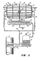
- a low grade heat source such as an exhaust stack 2 has placed within a heat absorption coil 4 of a closed loop heat transfer means containing a fluid such as water which absorbs a portion of the heat from the heat source when flowed through coil 4 then pumped through line 5 by pump 6 into the heat exchange coils 7 of a saturated vapor generating cell 10 of conventional means equipped with a pressure relief valve 12 and containing a quantity of liquefied working fluid 13 such as Freon which is heated sufficiently by regulating flow rates of pump 6 by conventional means to cause the liquefied working fluid to undergo a phase change to saturated vapor.
- the heat transfer fluid having given up its heat is recycled to heat source 2 through conduit 8.
- the saturated vapor of the working fluid flows through conduit 14 into the superheated vapor generating cell 16 equipped with a pressure relief valve 24 and which introduces additional heat supplied and controlled by conventional means such as burners 18, fueled by a fuel source and line 20, and regulated by conventional pressure and temperature controls.
- the working fluid passes through heating coils 22 picking up sufficient additional heat to become a superheated vapor and pass through throttling valve 26 through conduit 28 into high pressure fitting 30 in the outer shell 32 of the superheated vapor actuated power generating device 32 equipped with a pressure relief valve 44 and rotational power output shaft 46.
- Exiting from both ends of the low pressure vessel 94 of the superheated vapor actuated power generating device are cooling fluid inlet lines 118 and discharge lines 120. Liquefied working fluid is discharged through pressure fittings 112 into discharge lines 114 into tee fitting 121 and then through conduit 122 into the liquid reservoir of the saturated vapor generating cell 10, completing the closed loop of the working fluid.
- FIG. 2 illustrates the preferred embodiment of the superheated vapor actuated power generating device which comprises an inner cylindrical high pressure vessel formed by left and right walls 34 joined at 36 and sealed by conventional means 40 by seating in a notch 37 formed at the mating surfaces of the right and left sections of the outer shell 32 and mechanically compressed by a plurality of mechanical connections 38 around the exterior of the outer shell.
- the volume between the outer shell walls 32 and the high pressure vessel walls 34 is filled with a conventional structural and insulating material.
- Rotational output shaft 46 is journal at bearing 47 and connected to the yoke assembly 49 at the end of piston rod 48.
- Piston rod 50 is connected at the yoke assembly 49 by means of pin 52.
- High pressure piston 54 of bank A is connected to piston rod 48 and high pressure piston 54' of bank B is connected to piston rod 50 by means of pins 56. Except for the differences in the yoke connection ends of piston rods 48 and 50, the left bank A of the superheated vapor actuated power generating device and right bank B are mirror images of the other so the description of components apply to either bank. High pressure piston 54 is surrounded by rings 58 within cylinder sleeve 60.
- the volume 73 contiguous to the top face of high pressure piston 54 is either an isolated volume when communicating port 66 of electromagnetic valve 59 is in its central or closed position, in direct communication with the high pressure volume 35 by the radial alignment of communicating port 66 with the high pressure cylinder sleeve intake ports 65 and valve body ports 67, or in communication with high pressure cylinder discharge conduit 68 by the radial alignment of communicating port 66 with the high pressure cylinder discharge ports 62 and high pressure cylinder discharge conduits 68.
- the end wall of the high pressure cylinder is formed by the elongated cylindrical structure 74.
- Connecting rods 57 are attached to the top face of high pressure piston 54 and to the low pressure piston 76 with seals 75 and guides 77 surrounding the connecting rods 57.
- Exhaust gases from high pressure cylinder volume 73 are evacuated into the varying low pressure cylinder volume 81 contiguous to the bottom face of low pressure piston 76 determined by travel of low pressure piston 76 and caused to swirl within the low pressure cylinder volume 81 by the concave configuration 80 on the bottom face of low pressure piston 76 and the complimentary concave configuration 82 at the end wall of low pressure cylinders 87.
- the volume 81 contiguous to the bottom face of low pressure piston 76 being increased at a greater rate than the decreasing volume 73 contiguous to the top face of high pressure piston 54 plus the volume of conduits 68 causes a lower pressure resulting in a rapid expansion of working fluid into low pressure cylinder volume 81 resulting in near total evacuation of working fluid from high pressure cylinder volume 73 and the impartation of work on the bottom face of low pressure piston 76 in the form of expansion of the vapor and kinetic energy of the working fluid molecules while the top face of low pressure piston 76 is exposed to the lowest system pressure that occurs within the working fluid system in low pressure vessel volume/condenser 86.
- Porting into the low pressure cylinder volumes 81 is performed by an electromagnetic valves 79 mechanically similar to electromagnetic valves 59.
- the volume 83 contiguous to the top face of low pressure piston 76 is directly communicated with low pressure vessel volume/condenser 86 through a plurality of ports 84 in structure 85 which provides structural support for low pressure cylinder sleeve 105 and cylinder sleeve 89 of injector piston 90 with a plurality of piston rings 91.
- Low pressure vessel wall 94 equipped with pressure relief valve 95 is mechanically attached by conventional means 96 and conventional sealing means 99 at a plurality of flanges to end wall 92 and high pressure vessel outer shell 32.
- Injector piston 90 is directly connected by axial connecting rod 57 to low pressure piston 76 and high pressure piston 54.
- injector piston 90 As injector piston 90, low pressure piston 76, and high pressure piston 54 travel from top dead center to bottom dead center the vacuum caused by the increasing volume 93 causes check valve 92 to unseat and draw liquefied working fluid 103 through suction tube 100 and into injector volume 93.
- the increased pressure causes check valve 92 to seat and check valve 106 to unseat causing liquefied working fluid to be forced through pressure fitting 110 through the end wall of low pressure vessel 94 and secured by pressure fitting 112 and through working fluid discharge line 114.
- Working fluid exhausted into low pressure vessel volume/condenser 86 is cooled and liquefied by heat absorption through condenser tubes 88 by running a sufficient quantity of cooling fluid such as water through condenser tubes 88. Liquefaction of the working fluid decreases pressure to the lowest point in the closed working fluid loop allowing the greatest pressure differential to occur between the bottom face of high pressure piston 54 and the directly linked top face of low pressure piston 76 resulting in working forces applied parallel to the axis of piston movement.
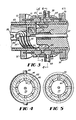
- FIG. 3 shows a double action electromagnetic valve assembly 59 which is mechanically similar to electromagnetic valve assembly 79 consisting of coils 70 and 70' encapsulated spring return assemblies 71 and slide valve bumpers 72.
- spring return assemblies 71 positions communicating ports 66 in their neutral or closed position.
- the slide body 102 moves to the right as illustrated in FIG. 3 which radially aligns communicating port 66 with cylinder discharge ports 62 with exhaust manifold 64 which in turn is connected to exhaust conduit 68 when the valve assembly is used in conjunction with high pressure cylinder 54 or to low pressure vessel volume/condenser 86 when used in conjunction with low pressure cylinder 105.
- Deactivation of coil 70 causes the slide body 102 to return to its closed position by forces exerted by spring return assemblies 71.
- the slide body 102 moves to the left as illustrated in FIG. 3 and radially aligns communicating ports 66 with cylinder intake ports 65 and valve body discharge ports 67 which communicates with high pressure vessel volume 35 when used in conjunction with high pressure cylinder 54 or to high pressure discharge conduit 68 when used in conjunction with low pressure cylinder 105.
- FIGS. 6 and 7 depict an alternate embodiment of the invention wherein manifold 136 collects exhaust from high pressure cylinder 60 through manifold 136 and transfers by conduit 138 through the end wall of low pressure vessel 94 through pressure fitting 140 through conduit 144 to reheater 146 containing heat element 148 and returned to the low pressure vessel end wall 94 through pressure fitting 152 through conduit 154 into collection manifold 156 which distributes reheated vapor to the intake port of low pressure cylinder 105. Also shown is alternate heat absorption means 155 being air-water heat absorption coil.
- FIG. 8 shows a modification wherein conduit 144 is routed through superheat vapor generating cell 16 and heat transfer tubes 160 returning to the end wall of low pressure vessel 94 through conduit 150. Also shown is an alternate heat source, which is a flow through hot water conduit 162.
Landscapes
- Engineering & Computer Science (AREA)
- Mechanical Engineering (AREA)
- General Engineering & Computer Science (AREA)
- Chemical & Material Sciences (AREA)
- Combustion & Propulsion (AREA)
- Engine Equipment That Uses Special Cycles (AREA)
- Physical Or Chemical Processes And Apparatus (AREA)
- Extraction Or Liquid Replacement (AREA)
- Compressors, Vaccum Pumps And Other Relevant Systems (AREA)
Priority Applications (1)
| Application Number | Priority Date | Filing Date | Title |
|---|---|---|---|
| AT85113333T ATE44799T1 (de) | 1984-10-25 | 1985-10-21 | Apparat fuer die umwandlung in mechanische energie von ueberhitztem dampf. |
Applications Claiming Priority (2)
| Application Number | Priority Date | Filing Date | Title |
|---|---|---|---|
| US664792 | 1984-10-25 | ||
| US06/664,792 US4603554A (en) | 1984-10-25 | 1984-10-25 | Method and apparatus for extracting useful energy from a superheated vapor actuated power generating device |
Publications (2)
| Publication Number | Publication Date |
|---|---|
| EP0179427A1 true EP0179427A1 (fr) | 1986-04-30 |
| EP0179427B1 EP0179427B1 (fr) | 1989-07-19 |
Family
ID=24667457
Family Applications (1)
| Application Number | Title | Priority Date | Filing Date |
|---|---|---|---|
| EP85113333A Expired EP0179427B1 (fr) | 1984-10-25 | 1985-10-21 | Appareil pour extraire de l'énergie à partir de vapeur surchauffée |
Country Status (8)
| Country | Link |
|---|---|
| US (1) | US4603554A (fr) |
| EP (1) | EP0179427B1 (fr) |
| JP (1) | JPS61108813A (fr) |
| AT (1) | ATE44799T1 (fr) |
| AU (2) | AU4896885A (fr) |
| CA (1) | CA1234293A (fr) |
| DE (1) | DE3571668D1 (fr) |
| MX (1) | MX162332A (fr) |
Cited By (3)
| Publication number | Priority date | Publication date | Assignee | Title |
|---|---|---|---|---|
| WO1998055734A1 (fr) * | 1997-06-06 | 1998-12-10 | Sobolewski, Walter | Moteur a vapeur haute pression |
| EP1942255A1 (fr) * | 2007-01-08 | 2008-07-09 | Huseyin Bayir | Moteur à énergie recyclable |
| WO2016032992A1 (fr) | 2014-08-27 | 2016-03-03 | The Procter & Gamble Company | Composition de détergent comprenant un polymère cationique |
Families Citing this family (5)
| Publication number | Priority date | Publication date | Assignee | Title |
|---|---|---|---|---|
| US4693087A (en) * | 1984-10-25 | 1987-09-15 | Thermal Engine Technology, Inc. | Method of generating power from a vapor |
| US4864826A (en) * | 1984-10-25 | 1989-09-12 | Lagow Ralph J | Method and apparatus for generating power from a vapor |
| US10018078B2 (en) * | 2009-05-21 | 2018-07-10 | Richard E. Aho | Apparatus for recovering energy from water |
| US8237299B2 (en) * | 2009-06-26 | 2012-08-07 | Larry Andrews | Power generation systems, processes for generating energy at an industrial mine site, water heating systems, and processes of heating water |
| US9574765B2 (en) | 2011-12-13 | 2017-02-21 | Richard E. Aho | Generation of steam by impact heating |
Citations (6)
| Publication number | Priority date | Publication date | Assignee | Title |
|---|---|---|---|---|
| DE46619C (de) * | CH. H. BENTON in London, 47 Upper Bedford Place | Dampfmaschine | ||
| DE51433C (de) * | A. F. barth in Grossenhain | Verbund-Dampfmaschine mit einseitigem Dampfeintritt | ||
| DE20771C (de) * | E. D. FARCOT in Paris | Neuerungen an Compound-Dampfmaschinen | ||
| DE41477C (de) * | J. ERICSSON in New-York, 262 Broadway | Neuerung an Verbunddampfmaschinen | ||
| GB140063A (en) * | 1919-03-08 | 1920-10-07 | Henry Benjamin Ford | Steam engine |
| CH132091A (de) * | 1927-12-06 | 1929-03-31 | Geka Ges Fuer Kaelteanlagen Mi | Einrichtung zur Erzielung eines stossfreien Ganges von Kolbenmaschinen. |
Family Cites Families (20)
| Publication number | Priority date | Publication date | Assignee | Title |
|---|---|---|---|---|
| US514573A (en) * | 1894-02-13 | de busini | ||
| US451342A (en) * | 1891-04-28 | Paul de susini | ||
| US670829A (en) * | 1900-05-12 | 1901-03-26 | Franz Windhausen Jr | Generator. |
| US756785A (en) * | 1900-10-12 | 1904-04-05 | Elizabeth S Galbraith | Apparatus for producing motive power from liquid gas. |
| US982449A (en) * | 1910-07-07 | 1911-01-24 | Joseph Timmins | Vapor-engine. |
| US3287901A (en) * | 1963-11-22 | 1966-11-29 | Atmospheric Energy Ltd | Closed cycle power generating apparatus |
| US3531933A (en) * | 1968-07-01 | 1970-10-06 | Oscar Conrad Baldwin | Isothermal expansion closed circuit power unit,using refrigerant superheated gas as the prime mover |
| US4109468A (en) * | 1973-04-18 | 1978-08-29 | Heath Willie L | Heat engine |
| FR2233871A5 (fr) * | 1973-06-14 | 1975-01-10 | Mengin Ets Pierre | |
| ZA747279B (en) * | 1973-11-15 | 1976-07-28 | C Kelsey | Solar driven power unit |
| US3950949A (en) * | 1974-03-26 | 1976-04-20 | Energy Technology Incorporated | Method of converting low-grade heat energy to useful mechanical power |
| US4018581A (en) * | 1974-12-17 | 1977-04-19 | John Denis Ruff | Solar heating system |
| US4033136A (en) * | 1975-11-20 | 1977-07-05 | Stewart Robert C | Vapor actuated power generating device |
| US4106581A (en) * | 1976-03-05 | 1978-08-15 | West Curtis W | Vehicle utilizing cryogenic fuel |
| US4102133A (en) * | 1977-04-21 | 1978-07-25 | James Hilbert Anderson | Multiple well dual fluid geothermal power cycle |
| US4209992A (en) * | 1977-11-04 | 1980-07-01 | Chih Kang Shao | Power generating method and apparatus |
| US4156343A (en) * | 1977-11-07 | 1979-05-29 | Stewart Robert C | Power generating assembly |
| US4285201A (en) * | 1977-11-07 | 1981-08-25 | Stewart Robert C | Vapor powered engine assembly |
| US4354565A (en) * | 1978-11-06 | 1982-10-19 | R & D Associates | Engine system using liquid air and combustible fuel |
| US4424678A (en) * | 1981-09-28 | 1984-01-10 | Kizziah Terrel A | Heat powered apparatus |
-
1984
- 1984-10-25 US US06/664,792 patent/US4603554A/en not_active Expired - Lifetime
-
1985
- 1985-10-17 CA CA000493170A patent/CA1234293A/fr not_active Expired
- 1985-10-21 EP EP85113333A patent/EP0179427B1/fr not_active Expired
- 1985-10-21 DE DE8585113333T patent/DE3571668D1/de not_active Expired
- 1985-10-21 AT AT85113333T patent/ATE44799T1/de active
- 1985-10-23 AU AU48968/85A patent/AU4896885A/en not_active Abandoned
- 1985-10-24 MX MX384A patent/MX162332A/es unknown
- 1985-10-25 JP JP60239274A patent/JPS61108813A/ja active Granted
-
1990
- 1990-02-19 AU AU49948/90A patent/AU628132B2/en not_active Ceased
Patent Citations (6)
| Publication number | Priority date | Publication date | Assignee | Title |
|---|---|---|---|---|
| DE46619C (de) * | CH. H. BENTON in London, 47 Upper Bedford Place | Dampfmaschine | ||
| DE51433C (de) * | A. F. barth in Grossenhain | Verbund-Dampfmaschine mit einseitigem Dampfeintritt | ||
| DE20771C (de) * | E. D. FARCOT in Paris | Neuerungen an Compound-Dampfmaschinen | ||
| DE41477C (de) * | J. ERICSSON in New-York, 262 Broadway | Neuerung an Verbunddampfmaschinen | ||
| GB140063A (en) * | 1919-03-08 | 1920-10-07 | Henry Benjamin Ford | Steam engine |
| CH132091A (de) * | 1927-12-06 | 1929-03-31 | Geka Ges Fuer Kaelteanlagen Mi | Einrichtung zur Erzielung eines stossfreien Ganges von Kolbenmaschinen. |
Cited By (3)
| Publication number | Priority date | Publication date | Assignee | Title |
|---|---|---|---|---|
| WO1998055734A1 (fr) * | 1997-06-06 | 1998-12-10 | Sobolewski, Walter | Moteur a vapeur haute pression |
| EP1942255A1 (fr) * | 2007-01-08 | 2008-07-09 | Huseyin Bayir | Moteur à énergie recyclable |
| WO2016032992A1 (fr) | 2014-08-27 | 2016-03-03 | The Procter & Gamble Company | Composition de détergent comprenant un polymère cationique |
Also Published As
| Publication number | Publication date |
|---|---|
| AU628132B2 (en) | 1992-09-10 |
| AU4994890A (en) | 1990-06-14 |
| DE3571668D1 (en) | 1989-08-24 |
| US4603554A (en) | 1986-08-05 |
| JPH0442523B2 (fr) | 1992-07-13 |
| CA1234293A (fr) | 1988-03-22 |
| AU4896885A (en) | 1986-05-01 |
| JPS61108813A (ja) | 1986-05-27 |
| ATE44799T1 (de) | 1989-08-15 |
| MX162332A (es) | 1991-04-26 |
| EP0179427B1 (fr) | 1989-07-19 |
Similar Documents
| Publication | Publication Date | Title |
|---|---|---|
| US4747271A (en) | Hydraulic external heat source engine | |
| US4077214A (en) | Condensing vapor heat engine with constant volume superheating and evaporating | |
| US4426847A (en) | Reciprocating heat engine | |
| US4555307A (en) | Sea water distillation system | |
| US4068476A (en) | Solar driven power unit | |
| US4864826A (en) | Method and apparatus for generating power from a vapor | |
| US4209982A (en) | Low temperature fluid energy conversion system | |
| US20120240897A1 (en) | Heat engine improvements | |
| US4603554A (en) | Method and apparatus for extracting useful energy from a superheated vapor actuated power generating device | |
| US20100186405A1 (en) | Heat engine and method of operation | |
| US20230102894A1 (en) | Vapor-powered liquid-driven turbine | |
| US4552514A (en) | Wave driven work extracting device | |
| US4693087A (en) | Method of generating power from a vapor | |
| JP2020525710A (ja) | 熱サイクルを実現するように構成された熱機械及びかかる熱機械によって熱サイクルを実現する方法 | |
| JPH11107856A (ja) | 単段および多段膨張スターリングエンジンエキスパンダ並 びにスターリングクーラ | |
| EP0061897B1 (fr) | Procédé et dispositif pour transformer l'énergie interne d'un fluide en énergie mécanique | |
| US4209992A (en) | Power generating method and apparatus | |
| RU2075599C1 (ru) | Способ преобразования теплоты в механическую работу и силовая установка для его осуществления | |
| US20050047935A1 (en) | Steam powered free piston pump | |
| WO2009055928A1 (fr) | Moteur hybride | |
| US4424678A (en) | Heat powered apparatus | |
| US11499501B2 (en) | Stirling engine design and assembly | |
| SU1539391A1 (ru) | Тепловой двигатель | |
| MX2010008098A (es) | Bomba de fluido para motor térmico, motor térmico, sistema térmico y metodo. | |
| GB2082683A (en) | External combustion reciprocating heat engine |
Legal Events
| Date | Code | Title | Description |
|---|---|---|---|
| PUAI | Public reference made under article 153(3) epc to a published international application that has entered the european phase |
Free format text: ORIGINAL CODE: 0009012 |
|
| AK | Designated contracting states |
Kind code of ref document: A1 Designated state(s): AT BE CH DE FR GB IT LI LU NL SE |
|
| 17P | Request for examination filed |
Effective date: 19860807 |
|
| 17Q | First examination report despatched |
Effective date: 19870429 |
|
| GRAA | (expected) grant |
Free format text: ORIGINAL CODE: 0009210 |
|
| AK | Designated contracting states |
Kind code of ref document: B1 Designated state(s): AT BE CH DE FR GB IT LI LU NL SE |
|
| REF | Corresponds to: |
Ref document number: 44799 Country of ref document: AT Date of ref document: 19890815 Kind code of ref document: T |
|
| ITF | It: translation for a ep patent filed | ||
| REF | Corresponds to: |
Ref document number: 3571668 Country of ref document: DE Date of ref document: 19890824 |
|
| ET | Fr: translation filed | ||
| PLBE | No opposition filed within time limit |
Free format text: ORIGINAL CODE: 0009261 |
|
| STAA | Information on the status of an ep patent application or granted ep patent |
Free format text: STATUS: NO OPPOSITION FILED WITHIN TIME LIMIT |
|
| 26N | No opposition filed | ||
| ITTA | It: last paid annual fee | ||
| PGFP | Annual fee paid to national office [announced via postgrant information from national office to epo] |
Ref country code: NL Payment date: 19921031 Year of fee payment: 8 |
|
| PGFP | Annual fee paid to national office [announced via postgrant information from national office to epo] |
Ref country code: SE Payment date: 19930426 Year of fee payment: 8 Ref country code: AT Payment date: 19930426 Year of fee payment: 8 |
|
| PGFP | Annual fee paid to national office [announced via postgrant information from national office to epo] |
Ref country code: CH Payment date: 19930427 Year of fee payment: 8 |
|
| PGFP | Annual fee paid to national office [announced via postgrant information from national office to epo] |
Ref country code: LU Payment date: 19930428 Year of fee payment: 8 |
|
| PGFP | Annual fee paid to national office [announced via postgrant information from national office to epo] |
Ref country code: FR Payment date: 19930429 Year of fee payment: 8 Ref country code: DE Payment date: 19930429 Year of fee payment: 8 Ref country code: BE Payment date: 19930429 Year of fee payment: 8 |
|
| EPTA | Lu: last paid annual fee | ||
| PG25 | Lapsed in a contracting state [announced via postgrant information from national office to epo] |
Ref country code: LU Free format text: LAPSE BECAUSE OF NON-PAYMENT OF DUE FEES Effective date: 19931021 Ref country code: AT Effective date: 19931021 |
|
| PG25 | Lapsed in a contracting state [announced via postgrant information from national office to epo] |
Ref country code: SE Effective date: 19931022 |
|
| PG25 | Lapsed in a contracting state [announced via postgrant information from national office to epo] |
Ref country code: LI Effective date: 19931031 Ref country code: CH Effective date: 19931031 Ref country code: BE Effective date: 19931031 |
|
| PGFP | Annual fee paid to national office [announced via postgrant information from national office to epo] |
Ref country code: GB Payment date: 19940421 Year of fee payment: 9 |
|
| BERE | Be: lapsed |
Owner name: THERMAL ENGINE TECHNOLOGY INC. Effective date: 19931031 |
|
| PG25 | Lapsed in a contracting state [announced via postgrant information from national office to epo] |
Ref country code: NL Effective date: 19940501 |
|
| NLV4 | Nl: lapsed or anulled due to non-payment of the annual fee | ||
| PG25 | Lapsed in a contracting state [announced via postgrant information from national office to epo] |
Ref country code: FR Effective date: 19940630 |
|
| REG | Reference to a national code |
Ref country code: CH Ref legal event code: PL |
|
| PG25 | Lapsed in a contracting state [announced via postgrant information from national office to epo] |
Ref country code: DE Effective date: 19940701 |
|
| REG | Reference to a national code |
Ref country code: FR Ref legal event code: ST |
|
| PG25 | Lapsed in a contracting state [announced via postgrant information from national office to epo] |
Ref country code: GB Effective date: 19941021 |
|
| EUG | Se: european patent has lapsed |
Ref document number: 85113333.0 Effective date: 19940510 |
|
| GBPC | Gb: european patent ceased through non-payment of renewal fee |
Effective date: 19941021 |