EP0179462A2 - Monture de lunettes et méthode d'assemblage - Google Patents
Monture de lunettes et méthode d'assemblage Download PDFInfo
- Publication number
- EP0179462A2 EP0179462A2 EP85113471A EP85113471A EP0179462A2 EP 0179462 A2 EP0179462 A2 EP 0179462A2 EP 85113471 A EP85113471 A EP 85113471A EP 85113471 A EP85113471 A EP 85113471A EP 0179462 A2 EP0179462 A2 EP 0179462A2
- Authority
- EP
- European Patent Office
- Prior art keywords
- temple
- pin
- receiving member
- eyeglass frame
- extension
- Prior art date
- Legal status (The legal status is an assumption and is not a legal conclusion. Google has not performed a legal analysis and makes no representation as to the accuracy of the status listed.)
- Granted
Links
Images
Classifications
-
- G—PHYSICS
- G02—OPTICS
- G02C—SPECTACLES; SUNGLASSES OR GOGGLES INSOFAR AS THEY HAVE THE SAME FEATURES AS SPECTACLES; CONTACT LENSES
- G02C5/00—Constructions of non-optical parts
- G02C5/22—Hinges
- G02C5/2209—Pivot bearings and hinge bolts other than screws
Definitions
- This invention relates to eyeglass frames, and a method of assembling same. More particularly, the invention is in the field of eyeglass frames which are easily and quickly assembled.
- the majority of eyeglass frames manufactured today include a lens supporting structure to which two temples are pivotably attached by means of a hinge assembly.
- the hinges can be metal or plastic, and a pin secures the hinge of the lens support to the hinge of the temple.
- the hinges are glued, screwed or fastened by sane other means to the lens support and tenple. Assembly of such frames utilizing metal or plastic hinges with a screw or pin assembly requires a number of manufacturing steps which complicates the assembly process.
- Eyeglass frames are also manufactured using other known pivoting connecting assemblies which provide free movement of the temples from the lens supporting structure.
- the basic requirement for any pivoting connector assembly is that the temple movement be made easily and the pivoting assembly be strong and reliable.
- the principal problem with all known assemblies, as in the case of the hinge assemblies described above, is that the assemblies are rather complex. This complexity results in added hardware costs as well as added assembly costs. In addition, sane of these assemblies provide inadequate strenght and reliability.
- a further object of the invention is to provide an easy and quick method of assembling an eyeglass frame. This object is solved according to claim 12. Further advantageous features of this method are evident from subclaim 13.
- the present invention allows production of an eyeglass frame the components of which can be inexpensively manufactured.
- the present invention also provides an eyeglass frame which is strong and reliable.
- an eyeglass frame and a method of assembling such a fram- in which the temple of the eyeglass frame includes a first extension portion projecting from the temple.
- This first extension portion includes a means to support a pin around which the temple pivots.
- a temple receiving member of a lens supporting structure includes upper and lower walls, the facing surfaces of which include a ramped slot. The first extension portion of the temple with the pin inserted in the pin support is aligned with the temple receiving member so that the pin slides through the ramped slots.
- the upper and lower walls of the temple receiving member separate until the pin -falls into a pin capturing hole in the temple receiving member where it locks thereby pivotably securing the temple to the supporting structure.
- a spring loaded pin is employed, at least one end of which depresses to allow the pin to pass through the slots.
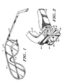
- the eyeglass frame 10, shown in Fig. 1 includes a lens supporting structure 12 and two temples 14,14'.
- An integral temple receiving member 13 extends in a generally perpendicular direction from each end of the lens supporting structure 12, and a temple 14 is pivotably connected to each of the temple receiving members 13.
- the temples 14, 14' pivot between an open position which enables a user to wear the eyeglasses and support the temples with his ears and a closed position which allows the eyeglasses to be stored.
- temple 14 is in a closed position and temple 14' is in an open position.
- the frame hinge assembly of the present invention enables a temple 14 to be easily and quickly secured to the lens supporting structure 12.
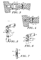
- Extending from this first extension portion 16 is a second extension portion 22 which is designed to fit within a second slot created between upper 24 and lower 26 outer walls of the temple receiving member 13.
- the first slot has a smaller depth than the temple 14 and the second slot has a depth smaller than the first slot.
- the temple 14 is fabricated so that the first extension portion 16 includes a pin receiving hole in which a pin 28 is inserted. This hole runs from the upper surface 30 of the first extension portion 16 to the lower surface 32 of the first extension portion 16 so that a pin may extend from both the upper and lower surfaces 30, 32 of the first extension portion 16.
- the interior upper 34 and lower 36 surfaces of the temple receiving member 13 include a ramped slot 34', 36', with the distance between opposed, ramped surfaces of the slots 34', 36' decreasing from the end 13a of temple receiving member 13 furthest from the position where a lens is supported to the pin-receiving hole 40 of the temple receiving member 13.
- the ramped surfaces are separated from each other a distance greater than the length of pin 28.
- the pin 28 is positioned so that the top end of the pin 28 slides into the upper slot 34' and the lower portion of the pin 28 slides into lower slot 36'.
- the temple 14, held in an open position as shown in a solid line in Fig. 5, is pushed towards the lens supporting structure l2 thereby forcing the upper and lower surfaces 34, 36 of the temple receiving member 13 apart from each other.
- surfaces 34, 36 continue to be separated from each other until the pin 28 falls into pin-receiving hole 40 at which point the surfaces 34, 36 collapse to substantially meet the surfaces 30, 32 of the first extension portion 16 of the temple 14.
- the pin 28 is then locked in hole 40.
- the temple 14 may be pivoted into contact with temple angular position limiting wall 19 once the temple 14 has been partially inserted into the temple receiving member 13. As shown in phantom in Fig. 5, this pivoting action forces the pin 28 towards the pin-receiving hole 40. With the pin locked in hole 40, the frame of the present invention provides a very strong hinge since the temple can only be separated from the lens supporting structure 12 by forcing apart the upper and lower surfaces 34, 36 of the temple receiving member 13. Under normal use, such a forcing apart is virtually impossible.
- the temple angular position limiting wall 19 integrally positioned between the upper and lower outside walls 24, 26 operates to limit the movement of the temple 14 in both the open and closed position. As shown in Fig. 6 the temple 14 pivots from an open to closed position making contact in both the open and closed position with temple limiting wall 19.
- the lens supporting structure 12 and the temples 14 are preferably fabricated from a polymer, particularly cellulose acetate propionate.
- the lens supporting structure 12 and/or the temples 14 may, however, be metal parts.
- the metal should be such that it will flex under the force of the pin 28 so as to allow the forcing apart of the upper and lower surfaces 34, 36 of the temple 14. It is also possible, however, to utilize a "stiffer" metal.
- Such a frame utilizes a pin 42 having at least one spring loaded insert 44 which depresses the spring 46 when the temple 14 is urged through the temple receiving member 13.
- the spring 46 forces the inserts 44 outwardly from the pin housing 48 thereby locking the pin in the pin receiving hole 40.
- the length of pin 42 must be greater than the closest distance.between the upper and lower surfaces 34, 36 of the temple receiving member 13.
- the eyeglass frame and assembly method taught by the present invention provides a sturdy and reliable eyeglass frame which is easily and quickly produced without a complex hinge assembly. As a result, both manufacturing and assembling costs are kept to a minimum thereby making the eyeglass frame a very appealing alternative to prior art eyeglass frame structures.
- the eyeglass frame of the present invention can be produced without the extension portions 16 and 22 of the temples being recessed.
- the frame can be manufactured from any material which will allow the upper and lower walls of the temple receiving member to spread apart upon impact of the force of the pin 28 being urged in the slot towards the lens supporting structure.
Landscapes
- Physics & Mathematics (AREA)
- Health & Medical Sciences (AREA)
- General Physics & Mathematics (AREA)
- Ophthalmology & Optometry (AREA)
- Optics & Photonics (AREA)
- Eyeglasses (AREA)
- Mirrors, Picture Frames, Photograph Stands, And Related Fastening Devices (AREA)
- Diaphragms For Electromechanical Transducers (AREA)
- Automobile Manufacture Line, Endless Track Vehicle, Trailer (AREA)
Priority Applications (1)
| Application Number | Priority Date | Filing Date | Title |
|---|---|---|---|
| AT85113471T ATE74446T1 (de) | 1984-10-23 | 1985-10-23 | Brillengestell und verfahren zum zusammenbau desselben. |
Applications Claiming Priority (2)
| Application Number | Priority Date | Filing Date | Title |
|---|---|---|---|
| US66386984A | 1984-10-23 | 1984-10-23 | |
| US663869 | 1984-10-23 |
Publications (3)
| Publication Number | Publication Date |
|---|---|
| EP0179462A2 true EP0179462A2 (fr) | 1986-04-30 |
| EP0179462A3 EP0179462A3 (en) | 1988-11-23 |
| EP0179462B1 EP0179462B1 (fr) | 1992-04-01 |
Family
ID=24663572
Family Applications (1)
| Application Number | Title | Priority Date | Filing Date |
|---|---|---|---|
| EP85113471A Expired - Lifetime EP0179462B1 (fr) | 1984-10-23 | 1985-10-23 | Monture de lunettes et méthode d'assemblage |
Country Status (5)
| Country | Link |
|---|---|
| EP (1) | EP0179462B1 (fr) |
| AT (1) | ATE74446T1 (fr) |
| BR (1) | BR8505175A (fr) |
| CA (1) | CA1290963C (fr) |
| DE (1) | DE3585771D1 (fr) |
Cited By (6)
| Publication number | Priority date | Publication date | Assignee | Title |
|---|---|---|---|---|
| DE3727861C1 (de) * | 1987-08-20 | 1988-06-16 | Simro Ag | Gelenk zum Verbinden eines Buegelschaftes mit einem Gelenkstueck einer Brille sowie Verfahren zur Herstellung eines solchen Gelenks |
| DE4132900A1 (de) * | 1991-10-04 | 1993-04-08 | Dieter Ammer | Brille |
| CN102573688A (zh) * | 2009-08-21 | 2012-07-11 | 爱尔康研究有限公司 | 具有可调目标的固定式光学系统 |
| EP2485080A1 (fr) * | 2011-02-07 | 2012-08-08 | Redtenbacher Präzisionsteile Ges. M.B.H. | Charnière à ressort pour lunettes |
| CN103907046A (zh) * | 2011-08-02 | 2014-07-02 | 张力 | 眼镜框,眼镜铰接件,以及眼镜框铰接件的装配方法 |
| US10114231B1 (en) * | 2015-03-27 | 2018-10-30 | Eric William Armstrong | Eyewear with detachable temples |
Families Citing this family (2)
| Publication number | Priority date | Publication date | Assignee | Title |
|---|---|---|---|---|
| AT401828B (de) * | 1993-01-15 | 1996-12-27 | Silhouette Int Gmbh | Scharniergelenk zwischen einem bügel und einem bügelbacken eines brillengestells |
| AT404193B (de) * | 1997-02-28 | 1998-09-25 | Redtenbacher Praezisionsteile | Scharniergelenk zwischen einem bügel und einem bügelbacken einer brille |
Family Cites Families (7)
| Publication number | Priority date | Publication date | Assignee | Title |
|---|---|---|---|---|
| GB638379A (en) * | 1940-01-04 | 1950-06-07 | American Optical Corp | Improvements in ophthalmic mountings |
| DE6801195U (de) * | 1967-10-31 | 1969-01-30 | Mazzucchelli Celluloids S P A | Scharnier zur verbindung der buegel mit dem gestell einer brille |
| JPS5511446Y2 (fr) * | 1975-02-28 | 1980-03-12 | ||
| FR2305751A1 (fr) * | 1975-03-25 | 1976-10-22 | Plastinax | Monture de lunettes |
| US4145124A (en) * | 1976-03-15 | 1979-03-20 | Weisgerber William C | Screw for eye glass frames |
| US4084889A (en) * | 1976-07-28 | 1978-04-18 | Vischer Optics, Inc. | Eyeglass frame |
| FR2363807A1 (fr) * | 1976-09-02 | 1978-03-31 | Jeunet Jean Pierre | Perfectionnements aux charnieres pour montures de lunettes |
-
1985
- 1985-09-06 CA CA000490124A patent/CA1290963C/fr not_active Expired - Fee Related
- 1985-10-17 BR BR8505175A patent/BR8505175A/pt not_active IP Right Cessation
- 1985-10-23 EP EP85113471A patent/EP0179462B1/fr not_active Expired - Lifetime
- 1985-10-23 DE DE8585113471T patent/DE3585771D1/de not_active Expired - Fee Related
- 1985-10-23 AT AT85113471T patent/ATE74446T1/de not_active IP Right Cessation
Cited By (8)
| Publication number | Priority date | Publication date | Assignee | Title |
|---|---|---|---|---|
| DE3727861C1 (de) * | 1987-08-20 | 1988-06-16 | Simro Ag | Gelenk zum Verbinden eines Buegelschaftes mit einem Gelenkstueck einer Brille sowie Verfahren zur Herstellung eines solchen Gelenks |
| DE4132900A1 (de) * | 1991-10-04 | 1993-04-08 | Dieter Ammer | Brille |
| CN102573688A (zh) * | 2009-08-21 | 2012-07-11 | 爱尔康研究有限公司 | 具有可调目标的固定式光学系统 |
| CN102573688B (zh) * | 2009-08-21 | 2015-07-29 | 爱尔康研究有限公司 | 具有可调目标的固定式光学系统 |
| EP2485080A1 (fr) * | 2011-02-07 | 2012-08-08 | Redtenbacher Präzisionsteile Ges. M.B.H. | Charnière à ressort pour lunettes |
| CN103907046A (zh) * | 2011-08-02 | 2014-07-02 | 张力 | 眼镜框,眼镜铰接件,以及眼镜框铰接件的装配方法 |
| CN103907046B (zh) * | 2011-08-02 | 2015-11-25 | 张力 | 眼镜框,眼镜铰接件,以及眼镜框铰接件的装配方法 |
| US10114231B1 (en) * | 2015-03-27 | 2018-10-30 | Eric William Armstrong | Eyewear with detachable temples |
Also Published As
| Publication number | Publication date |
|---|---|
| DE3585771D1 (de) | 1992-05-07 |
| ATE74446T1 (de) | 1992-04-15 |
| EP0179462B1 (fr) | 1992-04-01 |
| CA1290963C (fr) | 1991-10-22 |
| EP0179462A3 (en) | 1988-11-23 |
| BR8505175A (pt) | 1986-07-29 |
Similar Documents
| Publication | Publication Date | Title |
|---|---|---|
| US4968129A (en) | Eyeglass frame structures and method of assembling same | |
| US5818567A (en) | Frame structure for eyeglasses having a spring-hinge | |
| CA1267800A (fr) | Monture de lunettes, et son assemblage | |
| US4832478A (en) | Spectacle hinge assembly | |
| US5722121A (en) | Enclosure hinge | |
| US4978209A (en) | Hinge for spectacle frame | |
| CN102216831B (zh) | 用于眼镜框的弹性铰链元件 | |
| US7380935B2 (en) | Mechanical universal hinge | |
| US4832479A (en) | Spectacle frame with resilient hinges | |
| US6353965B1 (en) | Guiding sheath assembly for a hinge of an eyeglass frame | |
| KR100217496B1 (ko) | 스프링 힌지를 구비한 안경테 | |
| JPH0254214A (ja) | ヒンジ | |
| EP0179462A2 (fr) | Monture de lunettes et méthode d'assemblage | |
| EP0926530A1 (fr) | Structure de liaison entre verre et branche de lunettes | |
| US5984472A (en) | pair of eyeglasses and frames thereof | |
| CN1276065A (zh) | 眼镜架、眼镜及制造眼镜架的方法 | |
| US20050157253A1 (en) | Spectacle frame | |
| EP1646906B2 (fr) | Charniere montee en retrait et destinee a rendre elastiques les branches de lunettes | |
| US7178200B2 (en) | Hinge structure | |
| EP0877278A1 (fr) | Monture de lunettes avec charnières sans vis | |
| EP0596265B1 (fr) | Charnière élastique pour lunettes | |
| KR20000068576A (ko) | 신축성을 갖는 안경테 측면부의 경첩 | |
| US6247810B1 (en) | Hinge for eyeglasses | |
| US3243248A (en) | Spring loaded spectacle frame hinge | |
| JP2517271Y2 (ja) | めがね蝶番 |
Legal Events
| Date | Code | Title | Description |
|---|---|---|---|
| PUAI | Public reference made under article 153(3) epc to a published international application that has entered the european phase |
Free format text: ORIGINAL CODE: 0009012 |
|
| AK | Designated contracting states |
Kind code of ref document: A2 Designated state(s): AT BE CH DE FR GB IT LI LU NL SE |
|
| PUAL | Search report despatched |
Free format text: ORIGINAL CODE: 0009013 |
|
| AK | Designated contracting states |
Kind code of ref document: A3 Designated state(s): AT BE CH DE FR GB IT LI LU NL SE |
|
| 17P | Request for examination filed |
Effective date: 19890519 |
|
| 17Q | First examination report despatched |
Effective date: 19901102 |
|
| GRAA | (expected) grant |
Free format text: ORIGINAL CODE: 0009210 |
|
| ITF | It: translation for a ep patent filed | ||
| AK | Designated contracting states |
Kind code of ref document: B1 Designated state(s): AT BE CH DE FR GB IT LI LU NL SE |
|
| REF | Corresponds to: |
Ref document number: 74446 Country of ref document: AT Date of ref document: 19920415 Kind code of ref document: T |
|
| REF | Corresponds to: |
Ref document number: 3585771 Country of ref document: DE Date of ref document: 19920507 |
|
| ET | Fr: translation filed | ||
| ITTA | It: last paid annual fee | ||
| PLBE | No opposition filed within time limit |
Free format text: ORIGINAL CODE: 0009261 |
|
| STAA | Information on the status of an ep patent application or granted ep patent |
Free format text: STATUS: NO OPPOSITION FILED WITHIN TIME LIMIT |
|
| 26N | No opposition filed | ||
| REG | Reference to a national code |
Ref country code: FR Ref legal event code: TP |
|
| REG | Reference to a national code |
Ref country code: CH Ref legal event code: PUE Owner name: CABOT SAFETY CORPORATION |
|
| NLS | Nl: assignments of ep-patents |
Owner name: CABOT SAFETY CORPORATION TE SOUTHBRIDGE, MASSACHUS |
|
| REG | Reference to a national code |
Ref country code: GB Ref legal event code: 732E |
|
| ITPR | It: changes in ownership of a european patent |
Owner name: CESSIONE;CABOT SAFETY CORPORATION |
|
| EPTA | Lu: last paid annual fee | ||
| EAL | Se: european patent in force in sweden |
Ref document number: 85113471.8 |
|
| REG | Reference to a national code |
Ref country code: GB Ref legal event code: 732E |
|
| PGFP | Annual fee paid to national office [announced via postgrant information from national office to epo] |
Ref country code: LU Payment date: 19960901 Year of fee payment: 12 |
|
| PGFP | Annual fee paid to national office [announced via postgrant information from national office to epo] |
Ref country code: SE Payment date: 19960916 Year of fee payment: 12 Ref country code: NL Payment date: 19960916 Year of fee payment: 12 |
|
| PGFP | Annual fee paid to national office [announced via postgrant information from national office to epo] |
Ref country code: AT Payment date: 19960918 Year of fee payment: 12 |
|
| PGFP | Annual fee paid to national office [announced via postgrant information from national office to epo] |
Ref country code: CH Payment date: 19960924 Year of fee payment: 12 |
|
| PGFP | Annual fee paid to national office [announced via postgrant information from national office to epo] |
Ref country code: BE Payment date: 19960927 Year of fee payment: 12 |
|
| REG | Reference to a national code |
Ref country code: CH Ref legal event code: PUE Owner name: CABOT SAFETY CORPORATION TRANSFER- CABOT SAFETY IN Ref country code: CH Ref legal event code: NV Representative=s name: KIRKER & CIE SA |
|
| PG25 | Lapsed in a contracting state [announced via postgrant information from national office to epo] |
Ref country code: LU Free format text: LAPSE BECAUSE OF NON-PAYMENT OF DUE FEES Effective date: 19971023 Ref country code: AT Free format text: LAPSE BECAUSE OF NON-PAYMENT OF DUE FEES Effective date: 19971023 |
|
| PG25 | Lapsed in a contracting state [announced via postgrant information from national office to epo] |
Ref country code: SE Free format text: LAPSE BECAUSE OF NON-PAYMENT OF DUE FEES Effective date: 19971024 |
|
| PG25 | Lapsed in a contracting state [announced via postgrant information from national office to epo] |
Ref country code: LI Free format text: LAPSE BECAUSE OF NON-PAYMENT OF DUE FEES Effective date: 19971031 Ref country code: CH Free format text: LAPSE BECAUSE OF NON-PAYMENT OF DUE FEES Effective date: 19971031 Ref country code: BE Free format text: LAPSE BECAUSE OF NON-PAYMENT OF DUE FEES Effective date: 19971031 |
|
| BERE | Be: lapsed |
Owner name: CABOT SAFETY CORP. Effective date: 19971031 |
|
| PG25 | Lapsed in a contracting state [announced via postgrant information from national office to epo] |
Ref country code: NL Free format text: LAPSE BECAUSE OF NON-PAYMENT OF DUE FEES Effective date: 19980501 |
|
| REG | Reference to a national code |
Ref country code: CH Ref legal event code: PL |
|
| NLV4 | Nl: lapsed or anulled due to non-payment of the annual fee |
Effective date: 19980501 |
|
| EUG | Se: european patent has lapsed |
Ref document number: 85113471.8 |
|
| PGFP | Annual fee paid to national office [announced via postgrant information from national office to epo] |
Ref country code: FR Payment date: 19990930 Year of fee payment: 15 |
|
| PGFP | Annual fee paid to national office [announced via postgrant information from national office to epo] |
Ref country code: GB Payment date: 19991001 Year of fee payment: 15 Ref country code: DE Payment date: 19991001 Year of fee payment: 15 |
|
| PG25 | Lapsed in a contracting state [announced via postgrant information from national office to epo] |
Ref country code: GB Free format text: LAPSE BECAUSE OF NON-PAYMENT OF DUE FEES Effective date: 20001023 |
|
| GBPC | Gb: european patent ceased through non-payment of renewal fee |
Effective date: 20001023 |
|
| PG25 | Lapsed in a contracting state [announced via postgrant information from national office to epo] |
Ref country code: FR Free format text: LAPSE BECAUSE OF NON-PAYMENT OF DUE FEES Effective date: 20010629 |
|
| PG25 | Lapsed in a contracting state [announced via postgrant information from national office to epo] |
Ref country code: DE Free format text: LAPSE BECAUSE OF NON-PAYMENT OF DUE FEES Effective date: 20010703 |
|
| REG | Reference to a national code |
Ref country code: FR Ref legal event code: ST |