EP0179472A2 - Lampe à décharge à vapeur de mercure à basse pression à culot unique - Google Patents
Lampe à décharge à vapeur de mercure à basse pression à culot unique Download PDFInfo
- Publication number
- EP0179472A2 EP0179472A2 EP85113528A EP85113528A EP0179472A2 EP 0179472 A2 EP0179472 A2 EP 0179472A2 EP 85113528 A EP85113528 A EP 85113528A EP 85113528 A EP85113528 A EP 85113528A EP 0179472 A2 EP0179472 A2 EP 0179472A2
- Authority
- EP
- European Patent Office
- Prior art keywords
- base
- base body
- power supply
- discharge vessel
- discharge lamp
- Prior art date
- Legal status (The legal status is an assumption and is not a legal conclusion. Google has not performed a legal analysis and makes no representation as to the accuracy of the status listed.)
- Withdrawn
Links
Images
Classifications
-
- G—PHYSICS
- G11—INFORMATION STORAGE
- G11C—STATIC STORES
- G11C17/00—Read-only memories programmable only once; Semi-permanent stores, e.g. manually-replaceable information cards
-
- H—ELECTRICITY
- H01—ELECTRIC ELEMENTS
- H01J—ELECTRIC DISCHARGE TUBES OR DISCHARGE LAMPS
- H01J5/00—Details relating to vessels or to leading-in conductors common to two or more basic types of discharge tubes or lamps
- H01J5/50—Means forming part of the tube or lamps for the purpose of providing electrical connection to it
- H01J5/54—Means forming part of the tube or lamps for the purpose of providing electrical connection to it supported by a separate part, e.g. base
- H01J5/56—Shape of the separate part
-
- Y—GENERAL TAGGING OF NEW TECHNOLOGICAL DEVELOPMENTS; GENERAL TAGGING OF CROSS-SECTIONAL TECHNOLOGIES SPANNING OVER SEVERAL SECTIONS OF THE IPC; TECHNICAL SUBJECTS COVERED BY FORMER USPC CROSS-REFERENCE ART COLLECTIONS [XRACs] AND DIGESTS
- Y02—TECHNOLOGIES OR APPLICATIONS FOR MITIGATION OR ADAPTATION AGAINST CLIMATE CHANGE
- Y02B—CLIMATE CHANGE MITIGATION TECHNOLOGIES RELATED TO BUILDINGS, e.g. HOUSING, HOUSE APPLIANCES OR RELATED END-USER APPLICATIONS
- Y02B20/00—Energy efficient lighting technologies, e.g. halogen lamps or gas discharge lamps
Definitions
- the invention relates to a mercury vapor low-pressure discharge lamp with a base on one side, consisting of one or more discharge vessels, at the ends of which current leads are led out, and to a base body which at least surrounds the ends of the discharge vessel and is non-detachably connected thereto and to the part of which is used for incandescent lamps and is remote from the discharge vessel , wherein the base body contains a ballast and ignition device provided with current leads and current leads of the discharge vessel and / or the ballast and ignition device are fastened to the base.
- Lamps of this type are known as compact fluorescent lamps from the patent literature in various embodiments.
- the contact elements of the base sleeve here consist of a threaded sleeve and a ground contact.
- One power supply each of the discharge vessel and the ballast and ignition device is electrically conductively connected to the threaded sleeve or to the base contact of the base.
- the connection itself is usually made using soft soldering.
- the object of the invention is to design the structure of the socket body in such a way that even in the case of masahial assembly, the preliminary soldering does not occur here as side soldering,
- the contact between the base and at least one power supply means that this is fixed immovably between the soaksl and the part of the soccobody facing away from the discharge vessel by wedging.
- the sockwl body is provided on its part facing away from the discharge vessel for fixing the power supply with a groove in which the power supply is arranged.
- the groove is preferably provided in the end face of the otherwise hollow-cylindrical design tone, that part of the base body which faces away from the Eatladuags vessel.
- the groove can, however, also be arranged in the outer surface of the base of the base body facing away from the feed charge.
- the base is preferably fastened to the part of the base body facing away from the discharge vessel by punching, as a result of which the power supply is clamped on the soookal body from the inner wall of the soakal.
- the hollow cylindrical part of the base body facing away from the discharge vessel can also be provided with a thread corresponding to the base, so that the base is screwed on and the power supply is thereby fixed in the groove.
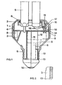
- the base body 1 is made of plastic and is composed of an upper part 2 and a lower part 3, which are mechanically non-detachably connected by means of a snap connection 4.
- the curved discharge vessel 5, which is coated with phosphor, is fastened to the upper part 2 with the aid of a temperature-hardenable cement 6.
- the discharge vessel 5 has an approximately U-shaped shape. However, two discharge vessels 5 of this type can also be connected, so that twice the discharge length results. In this case, the four straight legs are parallel to each other and arranged in a square. Furthermore, a plurality of two-leg discharge vessels 5 can also be fastened in the base body 1.
- a mounting plate 7 is attached, on which a ballast and ignition device 8 is mounted.
- An inductive ballast with starter or an electronic ballast is equally suitable for this.
- the mounting plate 7 is a printed circuit board on which the components of a high-frequency ballast are arranged. This offers the advantages of a higher luminous efficacy of the lamp as well as the significantly reduced weight compared to a conventional ballast.
- a base 9 is fastened, as is usually used for incandescent lamps. The base 9 enables the compact lamp to be directly connected to the socket of a lamp intended for incandescent lamps.
- a first power supply 11 is soldered to the ground contact 10 of the base 9 and leads through the cavity in the lower region of the base body 1 to the mounting plate 7.
- a second power supply 12 also leads from the mounting plate 7 through the cavity in the lower region of the lower part 3, is then further bent outwards at its lower edge and lies there in contact with the sleeve of the base 9.
- the lower part 3 is provided with an end groove 13 in which the power supply 12 is arranged and, after the base 9 has been fastened, it is absolutely secured by punching and fixed by clamping (FIG. 2). This creates a secure electrical connection between the second power supply 12 and the sleeve of the base 9.
- the electrical connection between the upper part 2 holding the discharge vessel 5 and the lower part 3 receiving the ballast and ignition device 8 takes place via the contact pins 14.
- plate 7 is pressed or soldered and are in electrical contact with the ballast and ignition device 8 via the conductor tracks of the mounting plate 7.
- Sockets 15 are formed on the upper part 2 and are provided with an insertion funnel 16 at the opening. It facilitates the mechanical insertion of the contact pins 14 into the blind hole arranged concentrically with the socket 15.
- the bushing 15 has a slot 17 tangent to this blind hole, which is provided with an insertion bevel 18 on the side facing the lower part 3. It facilitates the mechanical insertion of the power supply lines 19 into the slot 17.
- the power supply lines 19 of the discharge vessel 5 are inserted into the slots 17 of the sockets 15.
- the contact pins 14 have previously been connected to the mounting plate 7 as indicated above.
- the contact pins 14 are pressed into the blind holes in the sockets 15, the current leads 19 arranged in the slots 17 being fixed and contacted at the same time.
- the assembly process carried out here applies in the same way to all four existing contact pins 14 and power supply lines 19, of which only two have been shown in the drawing.
Landscapes
- Common Detailed Techniques For Electron Tubes Or Discharge Tubes (AREA)
- Fastening Of Light Sources Or Lamp Holders (AREA)
Applications Claiming Priority (2)
| Application Number | Priority Date | Filing Date | Title |
|---|---|---|---|
| DE19843439171 DE3439171A1 (de) | 1984-10-25 | 1984-10-25 | Einseitig gesockelte quecksilberdampfniederdruckentladungslampe |
| DE3439171 | 1984-10-25 |
Publications (2)
| Publication Number | Publication Date |
|---|---|
| EP0179472A2 true EP0179472A2 (fr) | 1986-04-30 |
| EP0179472A3 EP0179472A3 (fr) | 1988-10-05 |
Family
ID=6248782
Family Applications (1)
| Application Number | Title | Priority Date | Filing Date |
|---|---|---|---|
| EP85113528A Withdrawn EP0179472A3 (fr) | 1984-10-25 | 1985-10-24 | Lampe à décharge à vapeur de mercure à basse pression à culot unique |
Country Status (4)
| Country | Link |
|---|---|
| US (1) | US4695767A (fr) |
| EP (1) | EP0179472A3 (fr) |
| KR (1) | KR860003646A (fr) |
| DE (1) | DE3439171A1 (fr) |
Cited By (1)
| Publication number | Priority date | Publication date | Assignee | Title |
|---|---|---|---|---|
| EP0538799A1 (fr) * | 1991-10-25 | 1993-04-28 | TUNGSRAM Részvénytársaság | Lampe de décharge à basse pression fixée d'un côté |
Families Citing this family (15)
| Publication number | Priority date | Publication date | Assignee | Title |
|---|---|---|---|---|
| US4794301A (en) * | 1986-08-19 | 1988-12-27 | Kabushiki Kaisha Toshiba | Fluorescent lamp having a convoluted discharge passage and fluorescent lamp apparatus incorporating the same |
| FR2632774B1 (fr) * | 1988-06-13 | 1990-10-05 | Muessli Daniel | Lampe a decharge comportant un culot normalise |
| DE68912002T2 (de) * | 1988-07-01 | 1994-07-07 | Philips Nv | Elektrische Lampe. |
| AU106615S (en) | 1988-12-16 | 1990-02-01 | Combinova A B | Lamp adapter |
| USD321502S (en) | 1988-12-16 | 1991-11-12 | Combinova Ab | Adapter for compact discharge lamp |
| DE4012684A1 (de) * | 1990-04-20 | 1991-10-24 | Patent Treuhand Ges Fuer Elektrische Gluehlampen Mbh | Kompakte niederdruckentladungslampe |
| US5086249A (en) * | 1991-03-04 | 1992-02-04 | Gte Products Corporation | Compact discharge lamp unit and method for manufacturing same |
| HU214536B (hu) * | 1994-07-20 | 1998-03-30 | Ge Lighting Tungsram Rt. | Egyoldalon fejelt kisülőlámpa |
| US5772310A (en) * | 1995-07-05 | 1998-06-30 | General Electric Company | Discharge lamp cap and method for fixing the discharge tube |
| US5751105A (en) * | 1995-12-15 | 1998-05-12 | General Electric Company | Assembly arrangement for a compact fluorescent lamp |
| US5834884A (en) * | 1996-12-23 | 1998-11-10 | General Electric Company | Systematic configuration of compact fluorescent lamps for operation in a single-type ballast |
| JP3293601B2 (ja) | 1999-09-03 | 2002-06-17 | 松下電器産業株式会社 | 管球およびその製造方法 |
| CN1203522C (zh) * | 2000-03-21 | 2005-05-25 | 皇家菲利浦电子有限公司 | 放电灯 |
| US6445131B1 (en) | 2000-05-17 | 2002-09-03 | General Electric Company | Compact fluorescent lamp with built-in operating circuit |
| US7794282B1 (en) * | 2009-06-09 | 2010-09-14 | John Edward Barger | Lamp socket adapter/converter |
Family Cites Families (10)
| Publication number | Priority date | Publication date | Assignee | Title |
|---|---|---|---|---|
| US2736874A (en) * | 1951-12-26 | 1956-02-28 | Gen Electric | Electric lamp |
| GB73866A (fr) * | 1951-12-26 | |||
| DE944325C (de) * | 1953-03-20 | 1956-06-14 | Patra Patent Treuhand | Sockelbefestigung fuer elektrische Lampen und Entladungsgefaesse |
| NL6808365A (fr) * | 1967-06-26 | 1968-12-27 | ||
| NL7710409A (nl) * | 1977-09-23 | 1979-03-27 | Philips Nv | Werkwijze voor het vervaardigen van een elektrische lamp. |
| US4270071A (en) * | 1979-11-26 | 1981-05-26 | Westinghouse Electric Corp. | Composite base and ballast member for compact single-ended fluorescent lamp |
| US4456854A (en) * | 1980-07-15 | 1984-06-26 | Tokyo Shibaura Denki Kabushiki Kaisha | Compact fluorescent lamp |
| US4375607A (en) * | 1981-03-23 | 1983-03-01 | Westinghouse Electric Corp. | Compact lamp unit having plug-in fluorescent lamp and module components |
| JPS5960962A (ja) * | 1982-09-30 | 1984-04-07 | 株式会社東芝 | 管球 |
| US4547704A (en) * | 1983-08-01 | 1985-10-15 | General Electric Company | Higher efficiency incandescent lighting units |
-
1984
- 1984-10-25 DE DE19843439171 patent/DE3439171A1/de not_active Withdrawn
-
1985
- 1985-10-21 US US06/789,638 patent/US4695767A/en not_active Expired - Fee Related
- 1985-10-24 EP EP85113528A patent/EP0179472A3/fr not_active Withdrawn
- 1985-10-24 KR KR1019850007845A patent/KR860003646A/ko not_active Withdrawn
Cited By (1)
| Publication number | Priority date | Publication date | Assignee | Title |
|---|---|---|---|---|
| EP0538799A1 (fr) * | 1991-10-25 | 1993-04-28 | TUNGSRAM Részvénytársaság | Lampe de décharge à basse pression fixée d'un côté |
Also Published As
| Publication number | Publication date |
|---|---|
| EP0179472A3 (fr) | 1988-10-05 |
| KR860003646A (ko) | 1986-05-28 |
| US4695767A (en) | 1987-09-22 |
| DE3439171A1 (de) | 1986-05-07 |
Similar Documents
| Publication | Publication Date | Title |
|---|---|---|
| EP0247662A1 (fr) | Connexion de traversée pour signaux HF | |
| DE3439171A1 (de) | Einseitig gesockelte quecksilberdampfniederdruckentladungslampe | |
| EP0179473B1 (fr) | Adaptateur pour une lampe à décharge à basse pression à culot unique | |
| DE19857802A1 (de) | Kompakte Leuchtstofflampe mit internen Verbindungen | |
| EP0854497B1 (fr) | Lampe compacte à décharge basse pression | |
| DE10048986A1 (de) | Dielektrische Barrieren-Entladungslampe | |
| DE4201779A1 (de) | Niederdruckentladungslampe | |
| EP0923105B1 (fr) | Lampe à décharge à basse pression de type compact | |
| DE3439137A1 (de) | Einseitig gesockelte quecksilberdampfniederdruckentladungslampe | |
| DE60034284T2 (de) | Lampe mit Schraubsockel und im Sockelgehäuse enthaltene Elektronik, sowie Verfahren zur deren Herstellung | |
| DE8431416U1 (de) | Einseitig gesockelte Quecksilberdampfniederdruckentladungslampe | |
| EP0179251A2 (fr) | Lampe à décharge à vapeur de mercure à basse pression avec culot unique | |
| EP3435488B1 (fr) | Agencement d'appareils | |
| EP0508395B1 (fr) | Dispositif pour mise à la terre | |
| DE8430109U1 (de) | Kontaktelement | |
| DE10042133A1 (de) | Semileuchte zum Umrüsten von induktiven Leuchten auf elektronische T5-Leuchtstofflampen | |
| DE19509112A1 (de) | Kompaktleuchtstofflampe mit kreisrundem Gasentladungsgefäß | |
| EP1329932B1 (fr) | Lampe compacte à décharge à basse pression | |
| EP0459170B1 (fr) | Douille pour une ampoule miniature | |
| DE4220690A1 (de) | Anordnung der Bauelemente elektronischer Vorschaltgeräte für einseitig gesockelte Kompakt-Leuchtstofflampen | |
| WO1995020238A1 (fr) | Lampe compacte avec adaptateur | |
| WO2002073746A1 (fr) | Connecteur de lignes | |
| DE69703453T2 (de) | Vorrichtung zur herstellung eines kontakts mit einem sockelteil,insbesondere einer gasentladungslampe | |
| DE3439122A1 (de) | Einseitig gesockelte quecksilberdampfniederdruckentladungslampe | |
| EP0615660A1 (fr) | Borne pour un systeme d'allumage. |
Legal Events
| Date | Code | Title | Description |
|---|---|---|---|
| PUAI | Public reference made under article 153(3) epc to a published international application that has entered the european phase |
Free format text: ORIGINAL CODE: 0009012 |
|
| AK | Designated contracting states |
Kind code of ref document: A2 Designated state(s): DE FR GB IT |
|
| PUAL | Search report despatched |
Free format text: ORIGINAL CODE: 0009013 |
|
| RHK1 | Main classification (correction) |
Ipc: H01J 61/32 |
|
| AK | Designated contracting states |
Kind code of ref document: A3 Designated state(s): DE FR GB IT |
|
| 17P | Request for examination filed |
Effective date: 19881026 |
|
| 17Q | First examination report despatched |
Effective date: 19890206 |
|
| STAA | Information on the status of an ep patent application or granted ep patent |
Free format text: STATUS: THE APPLICATION HAS BEEN WITHDRAWN |
|
| 18W | Application withdrawn |
Withdrawal date: 19890410 |
|
| RIN1 | Information on inventor provided before grant (corrected) |
Inventor name: WITTMANN, HORST, DIPL.-ING. (FH) |