EP0179520A1 - Unité automatique d'application d'une bande adhésive avec système pour retirer les rouleaux applicateurs de bande pour machines de fermeture de boîtes - Google Patents
Unité automatique d'application d'une bande adhésive avec système pour retirer les rouleaux applicateurs de bande pour machines de fermeture de boîtes Download PDFInfo
- Publication number
- EP0179520A1 EP0179520A1 EP85201628A EP85201628A EP0179520A1 EP 0179520 A1 EP0179520 A1 EP 0179520A1 EP 85201628 A EP85201628 A EP 85201628A EP 85201628 A EP85201628 A EP 85201628A EP 0179520 A1 EP0179520 A1 EP 0179520A1
- Authority
- EP
- European Patent Office
- Prior art keywords
- roller
- carton
- inlet
- outlet
- tape
- Prior art date
- Legal status (The legal status is an assumption and is not a legal conclusion. Google has not performed a legal analysis and makes no representation as to the accuracy of the status listed.)
- Granted
Links
Images



Classifications
-
- B—PERFORMING OPERATIONS; TRANSPORTING
- B65—CONVEYING; PACKING; STORING; HANDLING THIN OR FILAMENTARY MATERIAL
- B65B—MACHINES, APPARATUS OR DEVICES FOR, OR METHODS OF, PACKAGING ARTICLES OR MATERIALS; UNPACKING
- B65B51/00—Devices for, or methods of, sealing or securing package folds or closures; Devices for gathering or twisting wrappers, or necks of bags
- B65B51/04—Applying separate sealing or securing members, e.g. clips
- B65B51/06—Applying adhesive tape
- B65B51/067—Applying adhesive tape to the closure flaps of boxes
Definitions
- the present invention relates to an automatic taping unit with improved system of withdrawal of the tape applying rollers for carton sealing machines.
- the above said machines employ automatic taping units arranged one below and the other above the advancement path of the cartons along a resting plane and suitably designed to allow the same carton to cause automatically the drawing, the cutting and the application of the correct length of tape.
- Conventional taping units include two rubber-like applying rollers arranged one at the inlet and the other at the outlet of the taping unit and elastically urged to project from the outline of the casing of the taping unit and in the carton advancement path, but, on the other hand, capable of returning within the same outline during the passage of the cartons.
- a cutting blade is also arranged between the two said rollers with similar features of return and projection with respect to the casing of the taping unit.
- the inlet roller has the function of causing an initial tape length to adhere to the front wall of the carton and then, once forced by the carton to return into the outline of the casing of the taping unit, of accompanying the following tape length, pulled by the carton, along the adiacent horizontal wall (top or bottom) of the carton and up to the rear wall of the latter.
- the outlet roller once overcome by the carton and thus let project from the outline of the casing of the taping unit, has in its turn the function of causing a final tape length to adhere to the rear wall of the carton.
- the cutting blade still after its overcoming by the advancing carton, has finally the function of carrying out the cutting of the tape between one carton and another, thereby fixing the length of said final tape length and that of the successive initial length for the following carton.
- a problem of these taping units is connected to the withdrawal and coming out movement of the tape applying rollers, which movement should be such as to allow the perfect adhesion of the initial and final tape length to the front and rear walls of the carton and, at the same time, to avoid possible jamming and damages of the carton.
- the object of the present invention is to realize an automatic taping unit for carton sealing machines, which includes withdrawal and coming-out mechanisms for the two taping applying rollers, which mechanisms allow to satisfy the above said requirements.
- the taping unit comprising a casing adapted to be fixed to a sealing machine along the carton advancement path, an inlet applying roller and an outlet applying roller elastically urged to project from said casing to be engaged and forced to return into said casing by the front of an advancing carton, an adhesive taping supply arranged to put, at rest, a free end of the tape in contact with said inlet roller in order to be engaged and adhesively drawn forward by the carton front and further realized in such a way as to allow subsequently said tape to follow the drawing of said free end and to slide on said inlet roller to extend adhesively along the adjacent horizontal wall of the carton, and a cutting blade arranged between said inlet and outlet rollers and provided with actuating means capable of causing it to return into the outline of said casing before being reached by the carton front and to project from said outline for cutting the tape between said inlet and outlet rollers after having been overcome by the rear wall of the carton and before said horizontal wall of the carton abandons said outlet roller, is mainly characterized in that said
- the inlet applying roller after an initial withdrawal movement with high vertical component which allows it the correct application of an initial tape length to the front wall of the carton and a successive progressive withdrawal movement with greater horizontal component, completes its return movement with a substantially vertical displacement which allows it to pass over the separation corner between the front wall and the adjacent horizontal wall of the carton without giving rise to jamming problems with said corner and to consequent possible damages for the carton.
- a possible swelling of the carton bottom is left without effect.
- Another feature included in the taping unit according to the invention is in its turn represented by the fact that said pair of support arms for the inlet applying roller is kinematically connected to a pair of support lever arms for the outlet applying roller, so that the withdrawal movement of the inlet applying roller under the thrust of the advancing carton and with the guide of said shaped windows is accompanied by a simultaneous withdrawal movement of the outlet applying roller through rotation of said pair of lever arms about a fixed fulcrum and the successive coming-out movement of the inlet applying roller for its return to the projected position is made dependent on a simultaneous coming-out movement of the outlet applying roller after its abandonment by said horizontal wall of the carton.
- the position of the fixed fulcrum about which the rotation of the outlet applying roller occurs is moreover chosen in such a way as to give said outlet roller a coming-out rotation with predominant horizontal component, which allows the same roller to carry out the correct application of the final tape section to the rear wall of the carton, while following the advancement movement of the same carton.
- the adhesive tape supply includes, upstream of the inlet applying roller, a succession of tape guiding and tensioning rollers, at least one of which is carried by movable support means associated to said blade actuating means in such a way as to cause tensioning of the adhesive tape when the cutting blade returns into the casing outline and to cause loosening of the tape tension when said actuating means control the subsequent coming out of the cutting blade for cutting the adhesive tape.
- the tape is correctly tensioned at the cutting time, but the tension is loosened immediately after, thereby avoiding possible problems of repositioning of the tape end, as due to excessive tension of the tape once the cutting has been executed.
- said succession of guiding rollers includes, downstream of said guiding roller carried by movable support means, an unidirectional roller arranged in such a position as to be progressively approached by said inlet applying roller during its withdrawal movement.
- the free end of the adhesive tape is always positioned in the same point of the inlet applying roller so as to ensure identical initial tape length for all the cartons.
- the use of adhesive tapes of different elasticity may produce different lenghtenings of the tape when in working tension for its application to the carton and such different lengthenings may produce, with tension loosened again, different locations of the free end of the tape on the inlet applying roller.
- said unidirectional guide roller is rotatably mounted on a support pivot, which is in its turn provided with an eccentric pivot and means are provided to change the angular position of said support pivot and of the respective guide roller with respect to said eccetric pivot.
- the distance, at rest, between said guide roller and the inlet applying roller may be changed so as to take into account and to compensate the different lengthening capacities of the several types of tape which may be used.
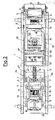
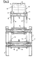
- the taping unit shown in the drawings comprises a casing 1 formed by two parallel walls 2 (connected by cross-members 47), between which the several members and operating mechanism of the unit are housed and supported.
- One of such members is a rubber-like applying inlet roller 3, which is rotatably mounted on pivot 4 arranged on a projecting end 5 of a pair of parallel arms 6, connected by cross-members 46 and having shaped windows 21 engaged with the fixed pivot 22.
- Another end of the arms 6 is hinged at 7 with a cooperating end of a pair of T-shaped levers 8 with fixed fulcrum 9 extending from one to another of the two sidewalls 2 of the casing 1.
- Another end of the T-shaped lever 8 in its turn is provided with a pin 10 with rollers 11 slidingly inserted in rectilinear windows 12 of a pair of lever arms 13, which carry a support pivot 14 for a rubber-like applying outlet roller 15.
- the lever arms 13 have a fixed fulcrum 16, on which there are also mounted integrally with the lever arms 13 two adjacent crank arms 17, to which there is attached at 18 a spring 19 adjustably drawn by a screw clamp 20.
- the above said mechanism keeps the two inlet and outlet rollers 3 and 15 projecting from the outline of the- casing- 1, at the same time allowing both rollers to return into the same outline under the thrust of an advancing carton 59, the first roller following a path, firstly inclined with great slope, then inclined with less slope, then almost wertical, which is defined by corresponding lower, intermediate and upper portions 23, 24 and 25 of the shaped windows 21 and the second roller following a curved path with great radius, which is defined by the rotation of the lever arms 13 about the fixed fulcrum 16.
- Two brushes 26 and 27 are fixed to the end 5 of the parallel arms 6 and to the T-shaped levers 8 for the purposes which will be described later.
- a brush 28 mounted on a resilient blade 29 extending from a bracket 30 fixed to the casing 1.
- a pair of wire springs 38 with elastic load adjustable by means of a clamp 39 engageable with either one or the other of a plurality of selectable holes 40 extends along the sidewalls 2 of the casing 1 up to engage a horizontal pin 41 (Fig. 4) to urge upwards resiliently the pair of levers 34 and consequently, through the pivot 13, the other pair of levers 32.
- an adhesive tape supplying system which has the function of unwinding progressively an adhesive tape 48 from a roll 49 rotatably carried by an arm 50 extending downwards from the casing 1 (Fig. 1).
- a pick-up and centering roller 51 (provided with sidewalls 71), which is rotatably carried by a lever arm 52 fulcrued at 53 on the casing 1 and subjected to the elastic stress of a spring 54.
- the tape 48 passes around the pick-up and centering roller 51, thereby inverting its direction movement, and then arrives with its free end at the inlet roller 3, progressively passing around guide rollers 55, 56, 57 and 58.
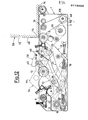
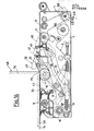
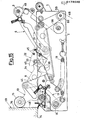
- the guide roller 55 is provided with sidewalls 72 for tape centering purposes and is rotatably mounted on the pair of levers 32 in such a way as to be movable along a circular path having its center on the axis of the pivot 31, as evidenced in Figs. 12, 13 and 14. The purpose and the result of this arrangement will be explained later.
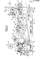
- the guide roller 56 of the one-way clutch type, is in its turn more advanced than the inlet roller 3 in the direction of advancement of the cartons to be sealed (arrow F in Fig. 11) and both the following guide rollers (57 and 58) are carried by the same lever arms 6 which carry the inlet roller 3 also.
- this allows the inlet roller 3 to approach progressively the guide roller 56 during its movement of return into the outline of the casing 1 under the thrust of an advancing carton 59, thereby loosening the tape length between the rollers 56 and 3 up to the time of the complete disappearing of the inlet roller 3 (Fig. 12).
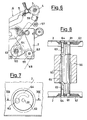
- the guide roller 56 has also the feature of being supported, through a free-wheel mechanism 65, by a support pivot 60 (Fig. 8), which is eccentrically mounted through trunnions 61 on the sidewalls 2 and at the center of rotatable disks 62, which are also fastened to the same pivot 60 by means of eccentric screws 63 passing through arcuated window 64 of the sidewalls 2 Fig. 7).
- the guide roller 56 may thus be selectively positioned in the position indicated in solid line in Fig. 6 or in that indicated in dash-dot line in the same Figure or further in several intermediate positions between the two above said. The purpose of this adjustment of position will be made clear later. Of course, similar results may be obtained through a translation, rather than an eccentric rotation of the pivot 60.
- taping unit illustrated in the drawings is provided with a cutting device which allows the cutting and the initial arrangement of the free end of the tape in an exact position in contact with the roller 3.
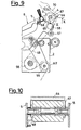
- said cutting device comprises a cutting blade 66 supported by an inversed-U frame 67, which is rotatably supported by the same rotation pin 4 of the inlet roller 3.
- a projection 68 of the frame 67 is able to engage a stationary abutment 69 supported by the end 5 of one of the two lever arms 6 to define the cutting position of the blade 66, shown in Fig. 9.
- the rest position is the diametrally opposed one of Fig. 1.
- the cartons to be sealed reach the taping unit by advancing, as known, on a resting plane coplanar with the top of the casing 1. At the inlet of the taping unit the cartons further rest on a support roller 71 supported by the casing (Fig. 11) and then prosecute (Figs. 12-14) along the top of the sidewalls 2.
- the several mechanisms of the taping unit start operation when the front wall 72 of the first carton 59 reaches the inlet roller 3. At that point, the free end of the adhesive tape 48 adheres with its adhesive face to said wall of the carton, using to this end the resistance of the inlet roller to the advancement of the carton.
- the withdrawal movement of the inlet roller 3 causes a certain approachment of the same roller to the unidirectional guide roller 56, the result being that the length of adhesive tape interposed between the rollers 3 and 56 takes a loose condition which avoids any necessity for the advancing carton to win the resistance and therefore to suffer the stresses of a tensioned tape. A possible damage for the carton is thus avoided, as well as a possible sliding of the tape along the carton wall.
- the carton draws the adhesive tape 48, retrieving the tape excess which caused the loose condition of Fig. 11 and tensioning the same tape.
- the further advancement of the carton causes the progressive unwinding of the tape from the roll 49 due to the drawing exerted by the same carton.
- a longer and longer length of tape thus adheres to the lower or bottom wall of the carton (really constituted by four inwardly bent flaps to define a longitudinal center slit along which the sealing tape 48 is applied), suitably pressed by the outlet and inlet rollers 15 and 13, on which it slides freely and is further smoothed by the brushes 28, 27 and 26.
- the engagement of the carton bottom with the actuating portions 43 and 44 of the two pairs of levers 32 and 34 further causes in this step the complete withdrawal of said pairs of levers into the outline of the casing. This situation is illustrated in Fig. 13 and, due to the increased distance between the roller 55 supported by the pair of levers 32 and the stationary roller 56, results into a suitable tensioning of the tape 48 in the area between the inlet and the outlet rollers 3 and 15.
- the cutting blade 37 carries out a sudden composed movement of rotation about the two pivots 31 and 33, that is with two lever arms which add to one another and produce double speed, and passing through the protecting bars 45 comes out of the outline of the casing 1 and of that of the pair of levers 32 to reach and cut the adhesive tape 48 between the two inlet and outlet rollers 3 and 15, thereby defining a final length of tape of prefixed length, equal to the distance between the actuating portion 43 and cutting blade 37.
- a tape length which a suitable choice of the position of the blade 37 makes equal to that of the initial length of tape defined between the guide roller 56 and the inlet roller in the rest position of Fig.
Landscapes
- Engineering & Computer Science (AREA)
- Mechanical Engineering (AREA)
- Package Closures (AREA)
- Making Paper Articles (AREA)
- Adhesive Tape Dispensing Devices (AREA)
- Manufacturing Cores, Coils, And Magnets (AREA)
- Diaphragms For Electromechanical Transducers (AREA)
- Manufacture Of Motors, Generators (AREA)
- Auxiliary Devices For And Details Of Packaging Control (AREA)
- Packages (AREA)
Priority Applications (1)
| Application Number | Priority Date | Filing Date | Title |
|---|---|---|---|
| AT85201628T ATE39453T1 (de) | 1984-10-17 | 1985-10-08 | Automatische klebestreifenanbringeinheit mit system zum zurueckziehen der streifenandruckrollen fuer kartonverschliessmaschinen. |
Applications Claiming Priority (2)
| Application Number | Priority Date | Filing Date | Title |
|---|---|---|---|
| IT2319284 | 1984-10-17 | ||
| IT23192/84A IT1176999B (it) | 1984-10-17 | 1984-10-17 | Unita' nastrante automatica con perfezionato sistema di rientro dei rulli applicatori per macchine per la sigillaturadi scatole di cartone |
Related Child Applications (1)
| Application Number | Title | Priority Date | Filing Date |
|---|---|---|---|
| EP87201651.4 Division-Into | 1987-08-31 |
Publications (2)
| Publication Number | Publication Date |
|---|---|
| EP0179520A1 true EP0179520A1 (fr) | 1986-04-30 |
| EP0179520B1 EP0179520B1 (fr) | 1988-12-28 |
Family
ID=11204738
Family Applications (2)
| Application Number | Title | Priority Date | Filing Date |
|---|---|---|---|
| EP87201651A Expired - Lifetime EP0251420B1 (fr) | 1984-10-17 | 1985-10-08 | Unité automatique d'application de ruban munie de moyens d'ajustement de ruban |
| EP85201628A Expired EP0179520B1 (fr) | 1984-10-17 | 1985-10-08 | Unité automatique d'application d'une bande adhésive avec système pour retirer les rouleaux applicateurs de bande pour machines de fermeture de boîtes |
Family Applications Before (1)
| Application Number | Title | Priority Date | Filing Date |
|---|---|---|---|
| EP87201651A Expired - Lifetime EP0251420B1 (fr) | 1984-10-17 | 1985-10-08 | Unité automatique d'application de ruban munie de moyens d'ajustement de ruban |
Country Status (10)
| Country | Link |
|---|---|
| US (2) | US4592188A (fr) |
| EP (2) | EP0251420B1 (fr) |
| JP (1) | JPS61104926A (fr) |
| AT (2) | ATE39453T1 (fr) |
| BR (1) | BR8505138A (fr) |
| CA (1) | CA1223235A (fr) |
| DE (2) | DE3582332D1 (fr) |
| DK (1) | DK157334C (fr) |
| ES (1) | ES8609119A1 (fr) |
| IT (1) | IT1176999B (fr) |
Cited By (3)
| Publication number | Priority date | Publication date | Assignee | Title |
|---|---|---|---|---|
| EP0369501A1 (fr) * | 1988-11-04 | 1990-05-23 | Augusto Marchetti | Unité d'application d'une bande adhésive pour machines d'application d'une bande adhésive sur des cartons avec un mouvement modifié pour le retour du rouleau applicateur d'entrée |
| US5374326A (en) * | 1992-07-17 | 1994-12-20 | Marchetti; Augusto | Sealing machine with two superimposed sealing units for parallelepiped boxes with down-turned flaps with simplified access to the lower sealing unit |
| WO2002002411A1 (fr) | 2000-07-06 | 2002-01-10 | Comarme Marchetti F.A. S.P.A. | Unite de rubanage pour une rubaneuse |
Families Citing this family (14)
| Publication number | Priority date | Publication date | Assignee | Title |
|---|---|---|---|---|
| US4991787A (en) * | 1989-03-15 | 1991-02-12 | Minnesota Mining And Manufacturing Company | Pivoting guide for web conveying apparatus |
| DE3938410A1 (de) * | 1989-11-18 | 1991-05-23 | Focke & Co | Vorrichtung zum anbringen eines klebestreifens an einem faltkarton oder dergleichen |
| US5228943A (en) * | 1990-06-04 | 1993-07-20 | Minnesota Mining And Manufacturing Company | Low impact tape applying device |
| US5286332A (en) * | 1990-09-10 | 1994-02-15 | Minnesota Mining And Manufacturing Company | Apparatus for applying an L clip tape to a cartridge |
| CA2117504A1 (fr) * | 1993-09-20 | 1995-03-21 | Karl M. Kropp | Scelleuse de boites equipee d'un systeme de detection servant a guider et a controler l'application du ruban adhesif |
| US6135937A (en) * | 1998-10-30 | 2000-10-24 | Ballos, Iii; Pete | Moveable tape head for erecting machine |
| US6615890B1 (en) | 2000-06-09 | 2003-09-09 | Venture Tape Corp. | Tape applicator for glazing applications |
| DE102009003550A1 (de) * | 2009-02-27 | 2010-09-09 | Reis Gmbh & Co. Kg Maschinenfabrik | Verfahren und Vorrichtung zum Bekleben eines Rands eines flächigen Objekts |
| US8327902B2 (en) * | 2010-06-04 | 2012-12-11 | Lamus Enterprises Inc | Tape delivery system for a tape applicator |
| TW201247401A (en) * | 2011-05-24 | 2012-12-01 | Yan-Cheng Ye | Shaping base of dual-rail packing machine |
| US9975724B2 (en) * | 2011-08-25 | 2018-05-22 | Lamus Enterprises Inc. | Tape applicator |
| US9457923B2 (en) | 2014-10-09 | 2016-10-04 | Lamus Enterprises Inc. | Tape applicator tab length control |
| CN108528845B (zh) * | 2018-06-13 | 2021-03-30 | 苏州全新机械配件有限公司 | 高效高速封箱机的机芯及其使用方法 |
| US12005651B2 (en) | 2020-11-20 | 2024-06-11 | Intertape Polymer Corp. | Tape applicator with split wiper |
Citations (3)
| Publication number | Priority date | Publication date | Assignee | Title |
|---|---|---|---|---|
| FR1384612A (fr) * | 1963-07-17 | 1965-01-08 | Fama | Machine à poser une bande adhésive sur un colis |
| US4061526A (en) * | 1976-07-13 | 1977-12-06 | The Loveshaw Corporation | Carton sealing machine having releasable latching means to hold retracted tape applying means while any carton travels therepast |
| FR2459757A1 (fr) * | 1979-06-27 | 1981-01-16 | Savoye | Machine a banderoler des emballages avec une bande adhesive |
Family Cites Families (9)
| Publication number | Priority date | Publication date | Assignee | Title |
|---|---|---|---|---|
| US2873039A (en) * | 1955-04-29 | 1959-02-10 | Adams Powel Equipment Ltd | Packing |
| US2799419A (en) * | 1955-07-28 | 1957-07-16 | Clybourn Machine Corp | Carton taping machine |
| US2861403A (en) * | 1956-02-27 | 1958-11-25 | Modern Coffees Inc | Infusion package with tab and method and apparatus for manufacture thereof |
| US2940233A (en) * | 1957-10-18 | 1960-06-14 | Package Machinery Co | Coupon attaching mechanism for bag forming machines |
| US3491657A (en) * | 1966-04-04 | 1970-01-27 | Closure Corp | Container closing device |
| US3466843A (en) * | 1967-03-24 | 1969-09-16 | George J Mumper | Carton closing and taping machine |
| US4120741A (en) * | 1976-11-12 | 1978-10-17 | Ab Akerlund & Rausing | Carton sealing strip applicator |
| US4227955A (en) * | 1979-01-08 | 1980-10-14 | Fmc Corporation | Article taping system |
| JPS5786437A (en) * | 1980-11-18 | 1982-05-29 | Showa Boueki Kk | Device for pasting tape |
-
1984
- 1984-10-17 IT IT23192/84A patent/IT1176999B/it active
-
1985
- 1985-10-08 AT AT85201628T patent/ATE39453T1/de not_active IP Right Cessation
- 1985-10-08 EP EP87201651A patent/EP0251420B1/fr not_active Expired - Lifetime
- 1985-10-08 AT AT87201651T patent/ATE61982T1/de active
- 1985-10-08 DE DE8787201651T patent/DE3582332D1/de not_active Expired - Lifetime
- 1985-10-08 DE DE8585201628T patent/DE3566996D1/de not_active Expired
- 1985-10-08 EP EP85201628A patent/EP0179520B1/fr not_active Expired
- 1985-10-11 CA CA000492813A patent/CA1223235A/fr not_active Expired
- 1985-10-16 US US06/788,223 patent/US4592188A/en not_active Expired - Lifetime
- 1985-10-16 JP JP60228989A patent/JPS61104926A/ja active Granted
- 1985-10-16 BR BR8505138A patent/BR8505138A/pt not_active IP Right Cessation
- 1985-10-17 ES ES547958A patent/ES8609119A1/es not_active Expired
- 1985-10-17 DK DK475885A patent/DK157334C/da not_active IP Right Cessation
-
1986
- 1986-06-02 US US06/869,561 patent/US4738075A/en not_active Expired - Lifetime
Patent Citations (3)
| Publication number | Priority date | Publication date | Assignee | Title |
|---|---|---|---|---|
| FR1384612A (fr) * | 1963-07-17 | 1965-01-08 | Fama | Machine à poser une bande adhésive sur un colis |
| US4061526A (en) * | 1976-07-13 | 1977-12-06 | The Loveshaw Corporation | Carton sealing machine having releasable latching means to hold retracted tape applying means while any carton travels therepast |
| FR2459757A1 (fr) * | 1979-06-27 | 1981-01-16 | Savoye | Machine a banderoler des emballages avec une bande adhesive |
Cited By (3)
| Publication number | Priority date | Publication date | Assignee | Title |
|---|---|---|---|---|
| EP0369501A1 (fr) * | 1988-11-04 | 1990-05-23 | Augusto Marchetti | Unité d'application d'une bande adhésive pour machines d'application d'une bande adhésive sur des cartons avec un mouvement modifié pour le retour du rouleau applicateur d'entrée |
| US5374326A (en) * | 1992-07-17 | 1994-12-20 | Marchetti; Augusto | Sealing machine with two superimposed sealing units for parallelepiped boxes with down-turned flaps with simplified access to the lower sealing unit |
| WO2002002411A1 (fr) | 2000-07-06 | 2002-01-10 | Comarme Marchetti F.A. S.P.A. | Unite de rubanage pour une rubaneuse |
Also Published As
| Publication number | Publication date |
|---|---|
| DE3582332D1 (de) | 1991-05-02 |
| US4592188A (en) | 1986-06-03 |
| ATE39453T1 (de) | 1989-01-15 |
| ES8609119A1 (es) | 1986-09-01 |
| IT8423192A1 (it) | 1986-04-17 |
| EP0251420A3 (en) | 1988-07-06 |
| IT8423192A0 (it) | 1984-10-17 |
| US4738075A (en) | 1988-04-19 |
| JPS61104926A (ja) | 1986-05-23 |
| JPH0571453B2 (fr) | 1993-10-07 |
| DK157334B (da) | 1989-12-18 |
| DE3566996D1 (en) | 1989-02-02 |
| DK157334C (da) | 1990-05-14 |
| IT1176999B (it) | 1987-08-26 |
| DK475885A (da) | 1986-04-18 |
| BR8505138A (pt) | 1986-07-29 |
| ES547958A0 (es) | 1986-09-01 |
| EP0179520B1 (fr) | 1988-12-28 |
| DK475885D0 (da) | 1985-10-17 |
| EP0251420B1 (fr) | 1991-03-27 |
| EP0251420A2 (fr) | 1988-01-07 |
| CA1223235A (fr) | 1987-06-23 |
| ATE61982T1 (de) | 1991-04-15 |
Similar Documents
| Publication | Publication Date | Title |
|---|---|---|
| US4738075A (en) | Automatic taping unit with improved system of withdrawal of the tape applying rollers for carton sealing machines | |
| US4011808A (en) | Strapping band guide for automatic strapping machine | |
| US4056128A (en) | Apparatus for producing a connection between two overlapping band sections of a package strip and improved closure seal for use therewith | |
| US4061526A (en) | Carton sealing machine having releasable latching means to hold retracted tape applying means while any carton travels therepast | |
| EP0181655B1 (fr) | Unité automatique d'application d'une bande adhésive avec système de coupe pour machines de fermeture de boîtes | |
| US5173140A (en) | Tape applying device and method for applying tape | |
| US5228943A (en) | Low impact tape applying device | |
| US4738483A (en) | Air guiding mechanism for an open roof construction, and an open roof construction provided with this air guiding mechanism | |
| CA2002123C (fr) | Machine servant a poser un ruban adhesif sur des boites de carton a dispositif d'introduction de rouleau ameliore | |
| US3039249A (en) | Tape wrapping machines | |
| US4827591A (en) | Manually operated clip attachment apparatus with movable gate and die | |
| US2511856A (en) | Device foe using adhesive tape | |
| US4192043A (en) | Closure seal and apparatus for applying the same | |
| EP0223271B1 (fr) | Dispositif pour distribuer de la bande adhésive à partir d'un rouleau d'approvisionnement | |
| JP3493502B2 (ja) | テーピング装置 | |
| US7726099B2 (en) | Semi-automatic (human powered) case sealing machine | |
| US4242770A (en) | Device for infeeding a strip of flexible material for use in machines for binding thin articles and, in particular, machines for edging parts for boots and shoes | |
| US4011977A (en) | Tape handling apparatus | |
| KR820000572Y1 (ko) | 포대입구등의 결속기 | |
| IL126648A (en) | Labelling machine | |
| JPS621884B2 (fr) | ||
| JPH01308723A (ja) | 袋体の口部封かん装置 |
Legal Events
| Date | Code | Title | Description |
|---|---|---|---|
| PUAI | Public reference made under article 153(3) epc to a published international application that has entered the european phase |
Free format text: ORIGINAL CODE: 0009012 |
|
| AK | Designated contracting states |
Kind code of ref document: A1 Designated state(s): AT BE CH DE FR GB IT LI LU NL SE |
|
| 17P | Request for examination filed |
Effective date: 19860923 |
|
| 17Q | First examination report despatched |
Effective date: 19870508 |
|
| GRAA | (expected) grant |
Free format text: ORIGINAL CODE: 0009210 |
|
| AK | Designated contracting states |
Kind code of ref document: B1 Designated state(s): AT BE CH DE FR GB IT LI LU NL SE |
|
| REF | Corresponds to: |
Ref document number: 39453 Country of ref document: AT Date of ref document: 19890115 Kind code of ref document: T |
|
| ITF | It: translation for a ep patent filed | ||
| REF | Corresponds to: |
Ref document number: 3566996 Country of ref document: DE Date of ref document: 19890202 |
|
| ET | Fr: translation filed | ||
| PLBE | No opposition filed within time limit |
Free format text: ORIGINAL CODE: 0009261 |
|
| STAA | Information on the status of an ep patent application or granted ep patent |
Free format text: STATUS: NO OPPOSITION FILED WITHIN TIME LIMIT |
|
| 26N | No opposition filed | ||
| ITTA | It: last paid annual fee | ||
| PGFP | Annual fee paid to national office [announced via postgrant information from national office to epo] |
Ref country code: SE Payment date: 19930927 Year of fee payment: 9 |
|
| PGFP | Annual fee paid to national office [announced via postgrant information from national office to epo] |
Ref country code: LU Payment date: 19930930 Year of fee payment: 9 Ref country code: CH Payment date: 19930930 Year of fee payment: 9 |
|
| EPTA | Lu: last paid annual fee | ||
| PG25 | Lapsed in a contracting state [announced via postgrant information from national office to epo] |
Ref country code: LU Free format text: LAPSE BECAUSE OF NON-PAYMENT OF DUE FEES Effective date: 19941008 |
|
| PG25 | Lapsed in a contracting state [announced via postgrant information from national office to epo] |
Ref country code: SE Effective date: 19941009 |
|
| PG25 | Lapsed in a contracting state [announced via postgrant information from national office to epo] |
Ref country code: LI Effective date: 19941031 Ref country code: CH Effective date: 19941031 |
|
| EAL | Se: european patent in force in sweden |
Ref document number: 85201628.6 |
|
| REG | Reference to a national code |
Ref country code: CH Ref legal event code: PL |
|
| EUG | Se: european patent has lapsed |
Ref document number: 85201628.6 |
|
| PGFP | Annual fee paid to national office [announced via postgrant information from national office to epo] |
Ref country code: AT Payment date: 19951013 Year of fee payment: 11 |
|
| PGFP | Annual fee paid to national office [announced via postgrant information from national office to epo] |
Ref country code: NL Payment date: 19951031 Year of fee payment: 11 |
|
| PG25 | Lapsed in a contracting state [announced via postgrant information from national office to epo] |
Ref country code: AT Effective date: 19961008 |
|
| PG25 | Lapsed in a contracting state [announced via postgrant information from national office to epo] |
Ref country code: NL Effective date: 19970501 |
|
| NLV4 | Nl: lapsed or anulled due to non-payment of the annual fee |
Effective date: 19970501 |
|
| PGFP | Annual fee paid to national office [announced via postgrant information from national office to epo] |
Ref country code: BE Payment date: 19971031 Year of fee payment: 13 |
|
| PGFP | Annual fee paid to national office [announced via postgrant information from national office to epo] |
Ref country code: FR Payment date: 19981007 Year of fee payment: 14 |
|
| PG25 | Lapsed in a contracting state [announced via postgrant information from national office to epo] |
Ref country code: BE Free format text: LAPSE BECAUSE OF NON-PAYMENT OF DUE FEES Effective date: 19981031 |
|
| BERE | Be: lapsed |
Owner name: MARCHETTI AUGUSTO Effective date: 19981031 |
|
| PGFP | Annual fee paid to national office [announced via postgrant information from national office to epo] |
Ref country code: GB Payment date: 19991006 Year of fee payment: 15 |
|
| PGFP | Annual fee paid to national office [announced via postgrant information from national office to epo] |
Ref country code: DE Payment date: 19991124 Year of fee payment: 15 |
|
| PG25 | Lapsed in a contracting state [announced via postgrant information from national office to epo] |
Ref country code: FR Free format text: LAPSE BECAUSE OF NON-PAYMENT OF DUE FEES Effective date: 20000630 |
|
| REG | Reference to a national code |
Ref country code: FR Ref legal event code: ST |
|
| PG25 | Lapsed in a contracting state [announced via postgrant information from national office to epo] |
Ref country code: GB Free format text: LAPSE BECAUSE OF NON-PAYMENT OF DUE FEES Effective date: 20001008 |
|
| GBPC | Gb: european patent ceased through non-payment of renewal fee |
Effective date: 20001008 |
|
| PG25 | Lapsed in a contracting state [announced via postgrant information from national office to epo] |
Ref country code: DE Free format text: LAPSE BECAUSE OF NON-PAYMENT OF DUE FEES Effective date: 20010703 |