EP0179534A2 - Installation de chauffage et de climatisation utilisant une pompe à chaleur - Google Patents
Installation de chauffage et de climatisation utilisant une pompe à chaleur Download PDFInfo
- Publication number
- EP0179534A2 EP0179534A2 EP85201711A EP85201711A EP0179534A2 EP 0179534 A2 EP0179534 A2 EP 0179534A2 EP 85201711 A EP85201711 A EP 85201711A EP 85201711 A EP85201711 A EP 85201711A EP 0179534 A2 EP0179534 A2 EP 0179534A2
- Authority
- EP
- European Patent Office
- Prior art keywords
- exchanger
- circuit
- heating
- valve
- heat transfer
- Prior art date
- Legal status (The legal status is an assumption and is not a legal conclusion. Google has not performed a legal analysis and makes no representation as to the accuracy of the status listed.)
- Withdrawn
Links
- 238000010438 heat treatment Methods 0.000 title claims abstract description 20
- 238000004378 air conditioning Methods 0.000 title claims abstract description 18
- 238000009434 installation Methods 0.000 title claims abstract description 16
- XLYOFNOQVPJJNP-UHFFFAOYSA-N water Substances O XLYOFNOQVPJJNP-UHFFFAOYSA-N 0.000 claims abstract description 38
- 239000013529 heat transfer fluid Substances 0.000 claims description 17
- 239000012530 fluid Substances 0.000 claims description 9
- 230000017525 heat dissipation Effects 0.000 claims description 4
- 239000002826 coolant Substances 0.000 claims description 2
- 241000283074 Equus asinus Species 0.000 claims 1
- 239000003638 chemical reducing agent Substances 0.000 claims 1
- 239000000284 extract Substances 0.000 claims 1
- 230000006835 compression Effects 0.000 description 4
- 238000007906 compression Methods 0.000 description 4
- 239000007788 liquid Substances 0.000 description 3
- 239000008236 heating water Substances 0.000 description 2
- 238000001816 cooling Methods 0.000 description 1
- 238000010586 diagram Methods 0.000 description 1
- 238000004519 manufacturing process Methods 0.000 description 1
Images

Classifications
-
- F—MECHANICAL ENGINEERING; LIGHTING; HEATING; WEAPONS; BLASTING
- F24—HEATING; RANGES; VENTILATING
- F24F—AIR-CONDITIONING; AIR-HUMIDIFICATION; VENTILATION; USE OF AIR CURRENTS FOR SCREENING
- F24F5/00—Air-conditioning systems or apparatus not covered by F24F1/00 or F24F3/00, e.g. using solar heat or combined with household units such as an oven or water heater
- F24F5/0046—Air-conditioning systems or apparatus not covered by F24F1/00 or F24F3/00, e.g. using solar heat or combined with household units such as an oven or water heater using natural energy, e.g. solar energy, energy from the ground
-
- F—MECHANICAL ENGINEERING; LIGHTING; HEATING; WEAPONS; BLASTING
- F24—HEATING; RANGES; VENTILATING
- F24D—DOMESTIC- OR SPACE-HEATING SYSTEMS, e.g. CENTRAL HEATING SYSTEMS; DOMESTIC HOT-WATER SUPPLY SYSTEMS; ELEMENTS OR COMPONENTS THEREFOR
- F24D3/00—Hot-water central heating systems
- F24D3/18—Hot-water central heating systems using heat pumps
-
- F—MECHANICAL ENGINEERING; LIGHTING; HEATING; WEAPONS; BLASTING
- F24—HEATING; RANGES; VENTILATING
- F24F—AIR-CONDITIONING; AIR-HUMIDIFICATION; VENTILATION; USE OF AIR CURRENTS FOR SCREENING
- F24F5/00—Air-conditioning systems or apparatus not covered by F24F1/00 or F24F3/00, e.g. using solar heat or combined with household units such as an oven or water heater
- F24F5/0096—Air-conditioning systems or apparatus not covered by F24F1/00 or F24F3/00, e.g. using solar heat or combined with household units such as an oven or water heater combined with domestic apparatus
-
- Y—GENERAL TAGGING OF NEW TECHNOLOGICAL DEVELOPMENTS; GENERAL TAGGING OF CROSS-SECTIONAL TECHNOLOGIES SPANNING OVER SEVERAL SECTIONS OF THE IPC; TECHNICAL SUBJECTS COVERED BY FORMER USPC CROSS-REFERENCE ART COLLECTIONS [XRACs] AND DIGESTS
- Y02—TECHNOLOGIES OR APPLICATIONS FOR MITIGATION OR ADAPTATION AGAINST CLIMATE CHANGE
- Y02B—CLIMATE CHANGE MITIGATION TECHNOLOGIES RELATED TO BUILDINGS, e.g. HOUSING, HOUSE APPLIANCES OR RELATED END-USER APPLICATIONS
- Y02B10/00—Integration of renewable energy sources in buildings
- Y02B10/20—Solar thermal
-
- Y—GENERAL TAGGING OF NEW TECHNOLOGICAL DEVELOPMENTS; GENERAL TAGGING OF CROSS-SECTIONAL TECHNOLOGIES SPANNING OVER SEVERAL SECTIONS OF THE IPC; TECHNICAL SUBJECTS COVERED BY FORMER USPC CROSS-REFERENCE ART COLLECTIONS [XRACs] AND DIGESTS
- Y02—TECHNOLOGIES OR APPLICATIONS FOR MITIGATION OR ADAPTATION AGAINST CLIMATE CHANGE
- Y02B—CLIMATE CHANGE MITIGATION TECHNOLOGIES RELATED TO BUILDINGS, e.g. HOUSING, HOUSE APPLIANCES OR RELATED END-USER APPLICATIONS
- Y02B10/00—Integration of renewable energy sources in buildings
- Y02B10/70—Hybrid systems, e.g. uninterruptible or back-up power supplies integrating renewable energies
-
- Y—GENERAL TAGGING OF NEW TECHNOLOGICAL DEVELOPMENTS; GENERAL TAGGING OF CROSS-SECTIONAL TECHNOLOGIES SPANNING OVER SEVERAL SECTIONS OF THE IPC; TECHNICAL SUBJECTS COVERED BY FORMER USPC CROSS-REFERENCE ART COLLECTIONS [XRACs] AND DIGESTS
- Y02—TECHNOLOGIES OR APPLICATIONS FOR MITIGATION OR ADAPTATION AGAINST CLIMATE CHANGE
- Y02B—CLIMATE CHANGE MITIGATION TECHNOLOGIES RELATED TO BUILDINGS, e.g. HOUSING, HOUSE APPLIANCES OR RELATED END-USER APPLICATIONS
- Y02B30/00—Energy efficient heating, ventilation or air conditioning [HVAC]
- Y02B30/12—Hot water central heating systems using heat pumps
Definitions
- the invention relates to a heating and air conditioning installation using a heat pump.
- An apparatus of this type is known for example from French patent 2,488,682 which comprises a first heat exchanger receiving the heat energy from the heat source, a compressor connecting the first heat exchanger to a second heat exchanger which supplies the heat energy in the heating circuit, the fluid compressed by the compressor expanding in an expansion valve and going to warm up in the first heat exchanger before restarting the thermal cycle.
- Such a device can only be used for space heating in the winter period and cannot provide air conditioning in the summer period. It is therefore necessary to provide a second installation intended for cooling. This solution is expensive due to the mandatory duplication of equipment.
- the invention provides an installation capable of providing heating and air conditioning with a majority of common elements.
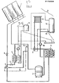
- the heating and air conditioning using a heat pump according to the embodiment shown, comprises a first exchanger 1 consisting of a solar panel. the outlet of which is connected to the intake of a compressor 2 which sends the compressed and hot heat transfer fluid into a second exchanger 3 where it transfers its calories to the water in the water circuit of said exchanger which feeds directly or indirectly heating appliances, hot water storage or heat removal devices in the atmosphere. This circuit will be described later.
- the compressed and cold heat transfer fluid leaving the exchanger 3 is expanded in a thermostatic expansion valve 4 then passes into the first exchanger 1 where it is heated before recommencing its compression-expansion cycle.
- a third exchanger 5 is provided at the outlet of the regulator 4 in which the relaxed and cold heat transfer fluid passes before reaching the inlet of the compressor 2.
- the fluid gives up its frigories to the water in the water circuit which supplies storage or dissipation devices for the cooled water.
- the heating or air conditioning operation is obtained by switching on the first exchanger 1 or the third exchanger 5 by opening or closing the valves 6 and 7 respectively on the input circuit of the first and third exchanger.
- the water circuit of the second exchanger 3 supplying the heating and / or heat dissipation circuit 8 comprises at its outlet a three-way valve 9 making it possible to direct the water either to a storage of hot water 10 supplying for example radiators, either on an air cooler 11 or other heat dissipation circuit in the colder environment.
- the water circuit 12 of the third exchanger 5 includes a storage of cooled water 13 supplying, for example, air conditioning apparatuses.
- the compressor 2 stops and the valve 6 is closed.
- the relaxed and cold heat transfer fluid then remains for a longer or shorter time in the solar panel 1 where it heats up.
- the control device 14 detects a temperature lower than the set temperature, the compressor 2 is started and the valve 6 open.
- the compressor 2 draws in the heat transfer fluid heated by its passage or its stay in the solar panel 1, and sends it after compression, in the exchanger 3 where it transfers its heat to the heating circuit 8.
- the heat transfer fluid is then expanded in the thermostatic expansion valve 4, the opening of which is controlled by a sensor 15 placed on the inlet pipe of the compressor 2.
- the regulator 4 controls the quantity of relaxed and cold coolant to be sent to the solar panel and diverts the part of the unused fluid towards the inlet of the compressor downstream of the sensor 15 by a bypass duct 16.
- Compressor 2 sucks the expanded heat transfer fluid which has given up its frigories to the cooled water storage circuit.
- the fluid After compression, the fluid passes through exchanger 3 where it gives up its calories (due to compression) to the circuit of the air cooler 11.
- the compressed heat transfer fluid is expanded in the expansion valve 4, a part of the relaxed and cold fluid passing directly through the bypass duct 16, at the inlet of the compressor 2, the other portion of the expanded fluid and cold passes into the third exchanger 5 and recommences its expansion compression cycle.
- the device 14 for controlling the temperature of the hot water storage 10 is put into service.
- the three-way valve 9 is open and ensures the passage of water from the second exchanger 3 to the storage of hot water 10.
- the control device 14 controls the three-way valve 9 which sends the water from the water circuit of the exchanger into the circuit of the air cooler 11 where it loses its calories in the colder ambient medium.
- the heating water and cooled water circuits include circulators 18 and 19 which allow the forced circulation of water and are put into service, for the heating water circulator 18, during "heating” operations. and “air conditioning” and, for the cooled water circulator 19 during operation in "air conditioning".
- the first exchanger which in the embodiment is one or more solar panels, can be constituted by an exchanger in a liquid medium, the natural source of heat then being a sheet or a stream.
- the air cooler 11 can be replaced by a heat dissipation circuit such as an exchanger in a liquid medium, the water in natural or forced flow ensuring the dissipation of calories.
- a heat dissipation circuit such as an exchanger in a liquid medium, the water in natural or forced flow ensuring the dissipation of calories.
Landscapes
- Engineering & Computer Science (AREA)
- Life Sciences & Earth Sciences (AREA)
- Chemical & Material Sciences (AREA)
- Combustion & Propulsion (AREA)
- Mechanical Engineering (AREA)
- General Engineering & Computer Science (AREA)
- Sustainable Development (AREA)
- Sustainable Energy (AREA)
- Physics & Mathematics (AREA)
- Thermal Sciences (AREA)
- Other Air-Conditioning Systems (AREA)
Abstract
Description
- L'invention concerne une installation de chauffage et de climatisation utilisant une pompe à chaleur.
- On connait des appareils de chauffage à circuit fermé capable d'extraire de l'énergie calorifique d'une source thermique naturelle solaire ou autre.
- Un appareil de ce type est connu par exemple du brevet français 2 488 682 qui comporte un premier échangeur de chaleur recevant l'énergie calorifique de la source thermique, un compresseur reliant le premier échangeur de chaleur à un deuxième échangeur qui fournit l'énergie calorifique au circuit de chauffage, le fluide comprimé par le compresseur se détendant dans une vanne de détente et allant se réchauffer dans le premier échangeur de chaleur avant de recommencer le cycle thermique.
- Un tel dispositif n'est utilisable que pour le chauffage de locaux en période hivernale et ne peut assurer la climatisation en période estivale. Il est par conséquent nécessaire de prévoir une deuxième installation destinée au refroidissement. Cette solution est onéreuse par suite de la duplication obligatoire du matériel. Ainsi l'invention propose une installation susceptible d'assurer le chauffage et la climatisation avec une majorité d'éléments communs.
- Les explications et figures données ci-après à titre d'exemple permettront de comprendre comment l'invention peut être réalisée :
- La figure 1 représente schématiquement une installation conforme à l'invention, dans la fonction chauffage.
- La figure 2 représente la même installation dans la fonction climatisation.
- L'installation de chauffage et de climatisation, utilisant une pompe à chaleur selon l'exemple de réalisation représenté, comporte un premier échangeur 1 constitué d'un panneau solaire.dont la sortie est branchée sur l'admission d'un compresseur 2 qui envoie le fluide caloporteur comprimé et chaud dans un deuxième échangeur 3 où il cède ses calories à l'eau du circuit d'eau dudit échangeur qui alimente directement ou indirectement des appareils de chauffage,de stockage d'eau chaude ou des appareils d'évacuation de la chaleur dans l'atmosphère. Ce circuit sera ultérieurement décrit.
- Le fluide caloporteur comprimé et froid sortant de l'échangeur 3 est détendu dans un détendeur thermostatique 4 puis passe dans le premier échangeur 1 où il est réchauffé avant de recommencer son cycle de compression-détente.
- Afin de permettre l'utilisation de ce circuit classique de pompe à chaleur en circuit de climatisation, on a prévu à la sortie du détendeur 4 un troisième échangeur 5 dans lequel le fluide caloporteur détendu et froid passe avant de se rendre à l'entrée du compresseur 2. Dans cet échangeur, le fluide cède ses frigories à l'eau du circuit d'eau qui alimente des appareils de stockage ou de dissipation de l'eau refroidie.
- Le fonctionnement en chauffage ou en climatisation est obtenu en mettant en circuit le premier échangeur 1 ou le troisième échangeur 5 par l'ouverture ou la fermeture des vannes 6 et 7 respectivement sur le circuit d'entrée du premier et du troisième échangeur.
- Le circuit d'eau du deuxième échangeur 3 alimentant le circuit de chauffage et/ou de dissipation de chaleur 8 comporte à sa sortie une vanne trois voies 9 permettant de diriger l'eau soit sur un stockage d'eau chaude 10 alimentant par exemple des radiateurs, soit sur un aéroréfrigérant 11 ou autre circuit de dissipation de la chaleur dans le milieu ambiant plus froid.
- Le circuit d'eau 12 du troisième échangeur 5 comporte un stockage d'eau refroidie 13 alimentant par exemple des appareils de climatisation de l'air.
- Le mode de fonctionnement de l'installation ci-dessus décrite est le suivant :
- On choisit le fonctionnement "chauffage" ou "climatisation" par mise sur l'une de ces positions d'un contacteur comportant des moyens pour la mise en ou hors circuit des éléments électriques ou électromagnétiques désignés ci-après sous la dénomination de vannes,de dispositif de contrôle de température et de détendeur.
- Sur la position chauffage (fig.1),(circuit représenté en double trait), la vanne trois voies 9 est au repos, le circuit d'eau de l'échangeur 3 étant relié au stockage d'eau chaude 10 ;
- - la vanne 7, commandant le passage du fluide caloporteur détendu et froid dans le troisième échangeur 5, est au repos et fermée ;
- - la vanne 6, commandant le passage du fluide caloporteur détendu et froid dans le premier échangeur 1, est mise en service de manière à suivre les arrêts démarrages du compresseur 2 ;
- - le dispositif de contrôle 14 de la température du stockage d'eau chaude 10 est mis en service,
- Lorsque la température de l'eau du stockage d'eau 10 est égale ou supérieure à la température de consigne du dispositif de contrôle 14, le compresseur 2 s'arrête et la vanne 6 est fermée. Le fluide caloporteur détendu et froid séjourne alors un temps plus ou moins long dans le panneau solaire 1 où il s'échauffe. Lorsque le dispositif de contrôle 14 détecte une température inférieure à la température de consigne, le compresseur 2 est mis en marche et la vanne 6 ouverte. Le compresseur 2 aspire le fluide caloporteur réchauffé par sa traversée ou son séjour dans le panneau solaire 1, et l'envoie après compression, dans l'échangeur 3 où il cède sa chaleur au circuit de chauffage 8.Le fluide caloporteur est ensuite détendu dans le détendeur thermostatique 4 dont l'ouverture est commandée par un senseur 15 placé sur la canalisation d'entrée du compresseur 2. Le détendeur 4 contrôle la quantité de fluide caloporteur détendu et froid à envoyer au panneau solaire et détourne la partie du fluide non utilisée vers l'entrée du compresseur en aval du senseur 15 par un conduit de dérivation 16.
- Sur la position "climatisation" (fig.2) (circuit représenté en double trait ), la vanne trois voies 9 est actionnée et le circuit d'eau de l'échangeur 3 est relié à l'aéroréfrigérant 11, le stockage d'eau chaude 10 étant mis hors circuit ;
- - la vanne 6 est fermée mettant hors circuit le panneau solaire 1 ;
- - la vanne 7,commandant le passage du fluide caloporteur détendu et froid vers le troisième échangeur 5 est mise en service de manière à suivre les arrêts démarrages du compresseur 2 ;
- - le dispositif de contrôle 17 de la température du stockage d'eau glacée 13 est mis en service. Lorsque la température de l'eau du stockage d'eau refroidie 13 est égale ou inférieure à la.température de consigne du dispositif de contrôle 17, le compresseur 2 est arrêté et la vanne 7 fermée, il n'y a plus de circulation de fluide caloporteur dans l'échangeur 5. Lorsque le dispositif de contrôle détecte une température supérieure à la température de consigne, le compresseur 2 est mis en marche et la vanne 7 est ouverte.
- Le compresseur 2 aspire le fluide caloporteur détendu qui a cédé ses frigories au circuit de stockage d'eau refroidie.
- Après compression, le fluide passe dans l'échangeur 3 où il cède ses calories (dues à la compression) au circuit de l'aéroréfrigérant 11. Le fluide caloporteur comprimé est détendu dans le détendeur 4, une partie du fluide détendu et froid passant directement par le conduit de dérivation 16, à l'entrée du compresseur 2, l'autre partie du fluide détendu et froid passe dans le troisième échangeur 5 et recommence son cycle de compression détente.
- Selon une variante du fonctionnement en "climatisation" avec production d'eau chaude, le dispositif de contrôle 14 de la température du stockage d'eau chaude 10 est mis en service. La vanne trois voies 9 est ouverte et assure le passage de l'eau du deuxième échangeur 3 vers le stockage d'eau chaude 10. Lorsque la température détectée par le dispositif de contrôle 14 est supérieure à la température de consigne, il. commande la vanne trois voies 9 qui envoie l'eau du circuit d'eau de l'échangeur dans le circuit de l'aéroréfrigérant 11 où il perd ses calories dans le milieu ambiant plus froid.
- Les circuits d'eau de chauffage et d'eau refroidie comportent des circulateurs 18 et 19 qui permettent la circulation forcée de l'eau et sont mis en service, pour le circulateur d'eau de chauffage 18,lors des fonctionnements en "chauffage" et "climatiàation" et, pour le circulateur d'eau refroidie 19 lors du fonctionnement en "climatisation".
- On n'a pas représenté sur les schémas les vannes à pression constante, bouteille anti coup de liquide, receveur et autres éléments tous bien connus des spécialistes et qui ne présentent aucun intérêt pour l'invention.
- Le premier échangeur, qui dans l'exemple de réalisation est un ou plusieurs panneaux solaires, peut être constitué par un échangeur en milieu liquide, la source naturelle de chaleur étant alors une nappe ou un cours d'eau.
- L'aéroréfrigérant 11 peut être remplacé par un circuit de dissipation de la chaleur tel qu'un échangeur en milieu liquide, l'eau en écoulement naturel ou forcé assurant la dissipation des calories.
Claims (4)
Applications Claiming Priority (2)
| Application Number | Priority Date | Filing Date | Title |
|---|---|---|---|
| CH505084 | 1984-10-22 | ||
| CH5050/84 | 1984-10-22 |
Publications (1)
| Publication Number | Publication Date |
|---|---|
| EP0179534A2 true EP0179534A2 (fr) | 1986-04-30 |
Family
ID=4287110
Family Applications (1)
| Application Number | Title | Priority Date | Filing Date |
|---|---|---|---|
| EP85201711A Withdrawn EP0179534A2 (fr) | 1984-10-22 | 1985-10-21 | Installation de chauffage et de climatisation utilisant une pompe à chaleur |
Country Status (1)
| Country | Link |
|---|---|
| EP (1) | EP0179534A2 (fr) |
Cited By (3)
| Publication number | Priority date | Publication date | Assignee | Title |
|---|---|---|---|---|
| WO1998058214A1 (fr) * | 1997-06-18 | 1998-12-23 | Giampaolo Bettelli | Dispositif d'air conditionne a usage domestique |
| FR2784595A1 (fr) | 1998-10-20 | 2000-04-21 | Salomon Sa | Chassis de patin en ligne a flasques lateraux independants |
| CN102087058A (zh) * | 2011-03-18 | 2011-06-08 | 苏州苏净安发空调有限公司 | 太阳能热泵三合一机组 |
-
1985
- 1985-10-21 EP EP85201711A patent/EP0179534A2/fr not_active Withdrawn
Cited By (3)
| Publication number | Priority date | Publication date | Assignee | Title |
|---|---|---|---|---|
| WO1998058214A1 (fr) * | 1997-06-18 | 1998-12-23 | Giampaolo Bettelli | Dispositif d'air conditionne a usage domestique |
| FR2784595A1 (fr) | 1998-10-20 | 2000-04-21 | Salomon Sa | Chassis de patin en ligne a flasques lateraux independants |
| CN102087058A (zh) * | 2011-03-18 | 2011-06-08 | 苏州苏净安发空调有限公司 | 太阳能热泵三合一机组 |
Similar Documents
| Publication | Publication Date | Title |
|---|---|---|
| US8037931B2 (en) | Hybrid water heating system | |
| US4453534A (en) | Solar water heating system | |
| JPH10238972A (ja) | 熱伝達装置 | |
| JP2005265249A (ja) | 給湯・空調システム | |
| JPS63289203A (ja) | エンジンの廃熱エネルギ−回収装置 | |
| JPS6343662B2 (fr) | ||
| NL8103967A (nl) | Werkwijze voor het bedrijven van verdichterinrichtingen voor gassen. | |
| US20060283404A1 (en) | Auxiliary device for a hot water device | |
| FR2598786A1 (fr) | Dispositif de production d'eau chaude par pompe a chaleur. | |
| JPH0413619B2 (fr) | ||
| JP6088771B2 (ja) | 熱源装置 | |
| GB2138122A (en) | Heating system | |
| US4601281A (en) | Hot water supply system | |
| RU14603U1 (ru) | Автономное устройство для тепло- и электроснабжения | |
| RU2830778C1 (ru) | Система охлаждения нереверсивного судового двигателя внутреннего сгорания | |
| RU2211943C2 (ru) | Система предпусковой тепловой подготовки двигателя внутреннего сгорания | |
| JP2002357329A (ja) | 温水供給装置 | |
| RU2015501C1 (ru) | Установка утилизации тепла выхлопных газов испытуемого воздушно-реактивного газотурбинного двигателя | |
| JPS60248945A (ja) | 給湯装置 | |
| WO2010055519A1 (fr) | Système antigivre pour collecteur de chauffage solaire | |
| CN209840446U (zh) | 一种制冷充气除水装置 | |
| JP2004028363A (ja) | ヒートポンプ式給湯機における凍結防止装置 | |
| FR2502753A1 (fr) | Dispositif automatique de regulation pour le prechauffage de l'eau sanitaire au moyen d'une pompe a chaleur | |
| JPS6225617Y2 (fr) | ||
| FR2468845A3 (fr) | Installation de chauffage bivalente comportant une pompe a chaleur a absorption |
Legal Events
| Date | Code | Title | Description |
|---|---|---|---|
| PUAI | Public reference made under article 153(3) epc to a published international application that has entered the european phase |
Free format text: ORIGINAL CODE: 0009012 |
|
| AK | Designated contracting states |
Kind code of ref document: A2 Designated state(s): AT BE DE FR GB IT LU NL SE |
|
| RAP1 | Party data changed (applicant data changed or rights of an application transferred) |
Owner name: BOUSHEHRI, MEHDI |
|
| RIN1 | Information on inventor provided before grant (corrected) |
Inventor name: MEFLAH, KAMEL Inventor name: BOUSHEHRI, MEHDI |
|
| STAA | Information on the status of an ep patent application or granted ep patent |
Free format text: STATUS: THE APPLICATION HAS BEEN WITHDRAWN |
|
| 18W | Application withdrawn |
Withdrawal date: 19871001 |
|
| RIN1 | Information on inventor provided before grant (corrected) |
Inventor name: MEFLAH, KAMEL Inventor name: BOUSHEHRI, MEHDI |