EP0179646A2 - Anordnung von Wärmetauscherrippen - Google Patents
Anordnung von Wärmetauscherrippen Download PDFInfo
- Publication number
- EP0179646A2 EP0179646A2 EP85307595A EP85307595A EP0179646A2 EP 0179646 A2 EP0179646 A2 EP 0179646A2 EP 85307595 A EP85307595 A EP 85307595A EP 85307595 A EP85307595 A EP 85307595A EP 0179646 A2 EP0179646 A2 EP 0179646A2
- Authority
- EP
- European Patent Office
- Prior art keywords
- array
- fin
- sub
- division
- pattern
- Prior art date
- Legal status (The legal status is an assumption and is not a legal conclusion. Google has not performed a legal analysis and makes no representation as to the accuracy of the status listed.)
- Granted
Links
Images






Classifications
-
- F—MECHANICAL ENGINEERING; LIGHTING; HEATING; WEAPONS; BLASTING
- F28—HEAT EXCHANGE IN GENERAL
- F28D—HEAT-EXCHANGE APPARATUS, NOT PROVIDED FOR IN ANOTHER SUBCLASS, IN WHICH THE HEAT-EXCHANGE MEDIA DO NOT COME INTO DIRECT CONTACT
- F28D1/00—Heat-exchange apparatus having stationary conduit assemblies for one heat-exchange medium only, the media being in contact with different sides of the conduit wall, in which the other heat-exchange medium is a large body of fluid, e.g. domestic or motor car radiators
- F28D1/02—Heat-exchange apparatus having stationary conduit assemblies for one heat-exchange medium only, the media being in contact with different sides of the conduit wall, in which the other heat-exchange medium is a large body of fluid, e.g. domestic or motor car radiators with heat-exchange conduits immersed in the body of fluid
- F28D1/04—Heat-exchange apparatus having stationary conduit assemblies for one heat-exchange medium only, the media being in contact with different sides of the conduit wall, in which the other heat-exchange medium is a large body of fluid, e.g. domestic or motor car radiators with heat-exchange conduits immersed in the body of fluid with tubular conduits
- F28D1/053—Heat-exchange apparatus having stationary conduit assemblies for one heat-exchange medium only, the media being in contact with different sides of the conduit wall, in which the other heat-exchange medium is a large body of fluid, e.g. domestic or motor car radiators with heat-exchange conduits immersed in the body of fluid with tubular conduits the conduits being straight
- F28D1/0535—Heat-exchange apparatus having stationary conduit assemblies for one heat-exchange medium only, the media being in contact with different sides of the conduit wall, in which the other heat-exchange medium is a large body of fluid, e.g. domestic or motor car radiators with heat-exchange conduits immersed in the body of fluid with tubular conduits the conduits being straight the conduits having a non-circular cross-section
- F28D1/05366—Assemblies of conduits connected to common headers, e.g. core type radiators
-
- B—PERFORMING OPERATIONS; TRANSPORTING
- B21—MECHANICAL METAL-WORKING WITHOUT ESSENTIALLY REMOVING MATERIAL; PUNCHING METAL
- B21D—WORKING OR PROCESSING OF SHEET METAL OR METAL TUBES, RODS OR PROFILES WITHOUT ESSENTIALLY REMOVING MATERIAL; PUNCHING METAL
- B21D13/00—Corrugating sheet metal, rods or profiles; Bending sheet metal, rods or profiles into wave form
- B21D13/02—Corrugating sheet metal, rods or profiles; Bending sheet metal, rods or profiles into wave form by pressing
-
- B—PERFORMING OPERATIONS; TRANSPORTING
- B21—MECHANICAL METAL-WORKING WITHOUT ESSENTIALLY REMOVING MATERIAL; PUNCHING METAL
- B21D—WORKING OR PROCESSING OF SHEET METAL OR METAL TUBES, RODS OR PROFILES WITHOUT ESSENTIALLY REMOVING MATERIAL; PUNCHING METAL
- B21D53/00—Making other particular articles
- B21D53/02—Making other particular articles heat exchangers or parts thereof, e.g. radiators, condensers fins, headers
- B21D53/08—Making other particular articles heat exchangers or parts thereof, e.g. radiators, condensers fins, headers of both metal tubes and sheet metal
-
- F—MECHANICAL ENGINEERING; LIGHTING; HEATING; WEAPONS; BLASTING
- F28—HEAT EXCHANGE IN GENERAL
- F28F—DETAILS OF HEAT-EXCHANGE AND HEAT-TRANSFER APPARATUS, OF GENERAL APPLICATION
- F28F1/00—Tubular elements; Assemblies of tubular elements
- F28F1/10—Tubular elements and assemblies thereof with means for increasing heat-transfer area, e.g. with fins, with projections, with recesses
- F28F1/12—Tubular elements and assemblies thereof with means for increasing heat-transfer area, e.g. with fins, with projections, with recesses the means being only outside the tubular element
- F28F1/126—Tubular elements and assemblies thereof with means for increasing heat-transfer area, e.g. with fins, with projections, with recesses the means being only outside the tubular element consisting of zig-zag shaped fins
-
- F—MECHANICAL ENGINEERING; LIGHTING; HEATING; WEAPONS; BLASTING
- F28—HEAT EXCHANGE IN GENERAL
- F28F—DETAILS OF HEAT-EXCHANGE AND HEAT-TRANSFER APPARATUS, OF GENERAL APPLICATION
- F28F3/00—Plate-like or laminated elements; Assemblies of plate-like or laminated elements
- F28F3/02—Elements or assemblies thereof with means for increasing heat-transfer area, e.g. with fins, with recesses, with corrugations
- F28F3/025—Elements or assemblies thereof with means for increasing heat-transfer area, e.g. with fins, with recesses, with corrugations the means being corrugated, plate-like elements
Definitions
- the present invention relates to heat exchanger fin arrays, to methods of making such arrays, to heat exchange sub-assemblies including such arrays, to methods of making such sub-assemblies and to apparatus for carrying out the methods.
- fin in this context is meant a heat conductive material for attachment to a heat exchanger, which material has a configuration intended to enhance heat transfer between the heat exchanger and the medium in which the heat exchanger is located by increasing the surface area across which heat transfer takes place.
- the invention relates particularly, though not exclusively, to the fins on hot water central heating panel radiators which comprise tubes and fins disposed transversely to one another.
- coils or strips of sheet metal of a variety of different widths are used, A coil or strip of a particular width is put in the fin-making apparatus, and the apparatus is then operated to produce a batch of fin arrays of that particular width. The coil or strip, if not completely used up, is then removed. The fin-making apparatus is then reset, a new coil or strip of a different width is put in the apparatus, and a further batch of a different width is produced. Either the production of the fin arrays must coincide with that of the panels to which the arrays are to be attached or alternatively fin arrays and/or panels must be stored until required. Furthermore coils or strips of a variety of different widths must be obtained and stocked.
- the invention provides a method of making heat exchanger fin arrays characterized in that arrays of one or a small number of uniform widths are made and are subsequently divided lengthwise into arrays of smaller width.
- the method has the advantage that only one or a small number of widths of heat conductive material need be obtained and stocked and that the fin making apparatus and the fin array attachment apparatus may operate at or near full capacity.
- the arrays are provided with a pattern of weaknesses or other physical alterations for facilitating lengthwise division.
- the pattern is repeated across the width of the array for facilitating division into any one of a number of different widths.
- the weaknesses include apertures each of which is capable of receiving a jaw of a cutting tool and capable of receiving a mounting bracket or mounting bracket engagement piece.
- the invention also provides a heat exchanger fin array characterized in that the array is provided with a pattern of weaknesses or other physical alterations for facilitating division into smaller arrays.
- the invention further provides a heat exchanger fin array characterized in that the array is made by lengthwise division of a larger fin array.
- the invention provides a method of making heat exchange sub-assemblies each including a fin array and at least one heat exchange element characterized in that the fin array is made by a method according to the invention and in that before lengthwise division of the array of uniform width it is attached to each one of a uniform number of heat exchange elements disposed parallel to the length of the array thereby to hold the elements in mutually fixed relationship.
- the invention also provides a sub-assembly for use in making a heat exchanger comprising a plurality of heat exchange elements held in mutually fixed relationship by a fin array which is joined to each one of them characterized in that the fin array is provided with a pattern of weaknesses or other physical alterations parallel to the length of the heat exchange elements for facilitating division of the sub-assembly into smaller sub-assemblies.
- the invention further provides a sub-assembly for use in making a heat exchanger comprising one or more heat exchange elements and a fin array joined to the or each heat exchange element characterized in that the sub-assembly is made from a sub-assembly comprising a plurality of heat exchange elements held in mutually fixed relationship by a fin array which is joined to each one of them, by division of the fin array parallel to the length of the heat exchange elements.
- the invention provides in combination, a heat exchanger including a fin array made by the method of the invention and one or more mounting brackets or mounting bracket engagement pieces projecting into one or more apertures of the array.
- the invention provides a method of making heat exchangers of a variety of desired different sizes characterized in that the method includes the steps of continuously making sub-assemblies according to the invention of one or a small number of uniform widths and dividing or joining such sub-assemblies as necessary to provide sub-assemblies of the desired variety of desired different sizes.
- the invention additionally provides apparatus for providing a pattern of weaknesses or other physical alterations on a length of sheet material for facilitating subsequent lengthwise division of the sheet material characterized in that the apparatus provides a pattern for facilitating division after the sheet material is subsequently formed into a heat exchanger fin array.
- the panel comprises flat tubes and fins disposed transversely to one another, to continuously produce a particular size of assembly such as, for example, eight flat tubes with connecting fins, and to subsequently divide the resulting assembly into smaller sizes, for example, six tubes and two tubes, by cutting the sheet metal in the region between two flat tubes, or, where a larger radiator (say ten tubes) is required, to add on extra tubes without or with fins.
- a manufacturer of finned central heating panel radiators where the panel comprises flat tubes and fins disposed transversely to one another, to continuously produce a particular size of assembly such as, for example, eight flat tubes with connecting fins, and to subsequently divide the resulting assembly into smaller sizes, for example, six tubes and two tubes, by cutting the sheet metal in the region between two flat tubes, or, where a larger radiator (say ten tubes) is required, to add on extra tubes without or with fins.
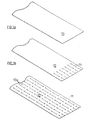
- Figure la shows an effectively continuous strip of sheet metal 10 (Figure la).
- Figures lb and lc show intermediate and final stages in the provision of a pattern 11 of parallel slits and slots. The method of and apparatus for producing the slit and slot pattern 11 will be described in more detail below.
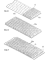
- Figure ld shows an intermediate stage in the provision of an array of fins 12.
- Figure le shows a length of slotted finned sheet metal cut from the continuous strip. The method of and apparatus for producing the array of fins 12 will also be described in more detail below.
- Figure If shows the length of slotted finned sheet metal attached by spot-welding to each one of a series of flat metal tubes 13.
- the spot-welding is carried out by passing the tubes 13 and the slotted finned sheet metal 10 through a multiple spot-welding machine. It will be appreciated from consideration of Figure lf that the tubes 13 are held in their mutually parallel co-planar relationship only by the unslit portions 12a of the fins.
- the standard width radiator sub-assembly comprising tubes 13 and array of fins 12 may then be divided into the smaller sub-assemblies shown in Figures Ig. The division is achieved by cutting the previously unslit portions 12a of the fins 12.
- a manufacturer can produce one standard width of radiator sub-assembly which can then be divided into any desired size. Cutting is done by means of a powered shears.
- an additional flat tube 13a without fins may be added to the sub-assembly where it is desired to produce a radiator in which it is not desired that the fin array should extend the full height of the radiator.
- larger radiator sub-assemblies of, say, twelve tubes may be made by simply joining two sub-assemblies of eight and four tubes.
- Unusual arrangements may be achieved if desired, such as for example panels in which the fins extend part way downwardly from the top of the radiator and part way upwardly from the bottom of the radiator but leave a gap in the middle for horizontally extending water connection pipes.
- radiators may thus be manufactured in a flowline in the following principal steps;
- Step (f) will now be described in more detail.
- the proportions into which the uniform width sub-assemblies are divided are arranged so that insofar as possible the smaller sub-assemblies are used immediately in the flowline production. Where it is not possible to use the smaller sub-assemblies immediately, they are moved to temporary storage for use as soon as possible. If the smaller sub-assemblies are of a particular size which is not likely to be used in the near future, such as for example, sub-assemblies comprising just one or two tubes, these may be joined together to make larger sub-assemblies. These larger sub-assemblies may be used as one panel of a double panel radiator so that the joint line between the fin arrays is concealed between the two panels of the radiator.
- each radiator required to be produced during a particular period, for example a week, may then be made from one or other width or by combining sub-assemblies obtained from the two different widths.
- the flowline described above can be used to make radiators other than the single panel finned radiators described above.
- double panel radiators may be made by joining two of the single panel radiators produced as described above.
- Unfinned radiators may also be made in the flowline by omitting most of the above described steps and just introducing the tubes and attaching the headers to them.
- fin arrays provided with a pattern of slots to facilitate subsequent division may also be used with panels other than those which comprise a series of unjoined elements. In such cases, lengthwise division of the fin arrays may be carried out before the fin arrays are attached to the panels.
- Figure 2a shows the preferred pattern 11 which consists of an array of longitudinal cuts k, having at each end thereof cut-outs or apertures j. The dotted lines indicate where the sheet metal will be folded.
- Figure 2b is a detail of the finished radiator, illustrating how the pattern 11 in Figure 2a appears in the finished radiator.
- Figure 2c is a view taken along IIC-IIC of Figure 2b. The various dimensions of the fin and slot patterns are represented in Figure 2a, 2b and 2c as "a”, "b", “c", "d” and "f".
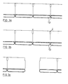
- FIG 3a is a view similar to 2c, showing a detail of the sub-assembly just before cutting. Cutting is done by means of a double-cutting powered hand-held shears (not shown) which removes (see Figure 3b) the bridging piece thereby dividing the assembly ( Figure 3c).
- the shape of the cut-out j is intended to accommodate the cutting tool and also to eliminate sharp corners in the finished product.
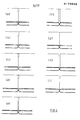
- Figure 4 (a) shows the presently preferred pattern 11 while Figures 4 (b) to 4 (i) show alternative patterns.
- the pattern should assist operation of the cutting tool; the pattern should not impede heat transfer from and within the fins and therefore the material removed should be as little as feasible and from as far away from the flat tubes as feasible; the pattern should not result in sharp corners in the finished product; the pattern should preferably not give an undesirable appearance to the finished product; and the pattern should not result in too great a reduction in the strength of the fins.
- the pattern of slits and slots does not impede conductive heat transfer within the fins, as such heat transfer takes place from the base of the fins along the walls to the top of the fins and is parallel to the pattern.
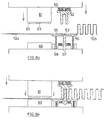
- FIG. 5 there is schematically illustrated a known method of making fins from a coil of sheet metal.
- the purpose of illustrating and describing the known method is to assist in understanding the method of the invention which will be described later.
- Figure 5a shows incoming sheet metal 10a from a coil which is not shown and outgoing finned metal lOb.
- An upper forming tool 52 moves vertically under the action of a power press and a lower forming tool 53 is stationary.
- a metal feed 54 Also shown are a metal feed 54, a pressure plate 55, a device 56 (shown as a spring in the Figure) for applying a controlled force to the pressure plate 55, and devices 57 which apply a controlled force to the pressure plate 55 near the end of the stroke considerably greater than the force applied by device 56.
- the devices 56 and 57 may, for example, comprise controlled hydraulic or pneumatic cylinders.
- the metal feed 54 has just fed the sheet metal 10a into position and the upper forming tool 52 is about to descend.
- the metal feeder 54 releases the sheet metal 10a and the upper forming tool 52 has descended to meet the sheet metal.
- the upper forming tool 52 continues to descend, causing the metal to wrap around the lower forming tool 53 drawing both the unformed and formed sheet metal towards the tool 53.
- the metal feed 54 returns to its home position.
- the upper forming tool 52 continues its descent, driving the pressure plate 55 ahead of it under relatively light pressure from device 56. At this point, devices 57 also come into play causing the sheet metal l ⁇ a to be gripped between the upper forming tool 52 and the pressure plate 55.
- the upper forming tool 52 descends just a little further causing the gripped metal 10a to be tightly wrapped around the corners of both the upper and lower forming tools 52, 53 and thus producing relatively well defined corners on the material.
- the upper forming tool 52 ascends and the pressure plate 55, under the action of device 56, follows the upper forming tool 52, pushing the formed fin 10b off the lower forming tool 53.
- the metal feed 54 closes to grip the metal.
- the upper forming tool 52 continues to the top of its stroke.
- the metal feed 54 moves the metal forward.
- the forming cycle has returned to the stage illustrated in Figure 5a. The cycle is automatically repeated, forming one fin for each press stroke.
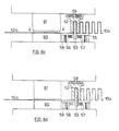
- the additional components include stops 58 which limit the downward movement of the pressure plate 55 and devices 59 which apply a controlled force to the top tool to overcome the forces applied by devices 56 and 57 and also the natural resistance to bending of the sheet metal.
- a fixed lower block 60 contains the piercing and lancing dies for the pattern and a moveable upper block 61 supports the piercing punches 62 and lancing punches 63 and moves vertically together with the upper fin forming tool 52 under the action of the power press.
- the pattern forming tool and the fin forming tool may be mounted in separate power presses.
- the sheet metal is then fed directly from thepattern forming tool and power press to the fin forming tool and power press using a pilot device to correctly locate the pattern in the fin forming tool.
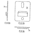
- the radiator is mounted (see Figure 7) on a wall by means of an engagement piece 70 (illustrated in Figure 8) which engages firstly in the slots which were provided in the side walls of the fins to assist cutting, and secondly in a wall mounted bracket 71 (illustrated in Figure 9).
- the engagement piece 70 may slide horizontally relative to the bracket 71. The horizontal movement allows greater tolerance in the fitting of the brackets 71 to the walls and also allows for thermal expansion of the radiator.
- the mounting arrangement has a number of advantages. Firstly, it is not necessary to permanently attach any additional part or component to the radiator or to modify the radiator in any way to receive mounting hooks or brackets. Secondly, flexibility is offered in the choice of bracket location because there is an entire array of slots available.
- the mounting arrangement is at the back of the panel where it is concealed, which is aesthetically pleasing.
- the mounting arrangement is relatively inexpensive.
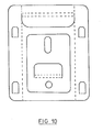
- Figure 10 shows how the engagement piece 70 and bracket 71 may both be pressed from a single piece of metal.
- the engagement piece 70 could be supported by a floor mounted bracket.
- the first variation comprises making a sub-assembly with fin arrays on both sides and subsequently dividing it into smaller sub-assemblies.
- the second variation comprises limiting the pattern to that necessary for division, such limitation may for examle be for aesthetic reasons or to reduce tool wear or to maintain fin strength.
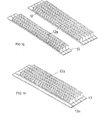
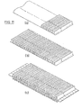
- Figure lla shows an intermediate stage in the production of one fin array from a length of sheet metal.
- a pattern of slits and slots has been provided to facilitate subsequent lengthwise division.
- the pattern comprises a single line of slits and slots. Fins have been formed along part of the continuous length.
- Figure llc shows the fin array attached to flat tubes to form a sub-assembly and also shows a second fin array attached to the other side of the flat tubes.
- Figure lld shows two sub-assemblies of smaller width obtained by lengthwise division of the sub-assembly of Figure llc along the lines of slits and slots.
Landscapes
- Engineering & Computer Science (AREA)
- Mechanical Engineering (AREA)
- Physics & Mathematics (AREA)
- Thermal Sciences (AREA)
- General Engineering & Computer Science (AREA)
- Geometry (AREA)
- Heat-Exchange Devices With Radiators And Conduit Assemblies (AREA)
- Separation By Low-Temperature Treatments (AREA)
- Filling Or Discharging Of Gas Storage Vessels (AREA)
Priority Applications (1)
| Application Number | Priority Date | Filing Date | Title |
|---|---|---|---|
| AT85307595T ATE65950T1 (de) | 1984-10-02 | 1985-10-21 | Anordnung von waermetauscherrippen. |
Applications Claiming Priority (2)
| Application Number | Priority Date | Filing Date | Title |
|---|---|---|---|
| IE271184A IE58157B1 (en) | 1984-10-02 | 1984-10-02 | Heat exchanger fin array |
| IE271184 | 1984-10-22 |
Publications (3)
| Publication Number | Publication Date |
|---|---|
| EP0179646A2 true EP0179646A2 (de) | 1986-04-30 |
| EP0179646A3 EP0179646A3 (en) | 1987-09-23 |
| EP0179646B1 EP0179646B1 (de) | 1991-08-07 |
Family
ID=11036142
Family Applications (1)
| Application Number | Title | Priority Date | Filing Date |
|---|---|---|---|
| EP85307595A Expired - Lifetime EP0179646B1 (de) | 1984-10-02 | 1985-10-21 | Anordnung von Wärmetauscherrippen |
Country Status (4)
| Country | Link |
|---|---|
| EP (1) | EP0179646B1 (de) |
| AT (1) | ATE65950T1 (de) |
| DE (1) | DE3583723D1 (de) |
| IE (1) | IE58157B1 (de) |
Cited By (11)
| Publication number | Priority date | Publication date | Assignee | Title |
|---|---|---|---|---|
| EP1113236A1 (de) * | 1999-12-28 | 2001-07-04 | Electrolux Zanussi S.p.A. | Verfahren und Anordung zum Herstellen von Kühlschrankkondensatoren |
| EP1176378A1 (de) * | 2000-07-25 | 2002-01-30 | Valeo Thermique Moteur | Verfahren zur Herstellung einer Rippe für einen Wärmetauscher, Rippe nach solchem Verfahren und Wärmeaustauschsmodul mit solchen Rippen |
| FR2849174A1 (fr) * | 2002-12-23 | 2004-06-25 | Valeo Thermique Moteur Sa | Ailette d'echange de chaleur, notamment de refroidissement, module d'echange de chaleur comprenant une telle ailette et procede de fabrication d'echangeurs de chaleur utilisant ladite ailette |
| EP1331463A3 (de) * | 2002-01-25 | 2006-07-12 | Calsonic Kansei Corporation | Integrierter Wärmetauscher und Verfahren zu dessen Herstellung |
| US7921559B2 (en) | 2006-01-19 | 2011-04-12 | Modine Manufacturing Company | Flat tube, flat tube heat exchanger, and method of manufacturing same |
| US8091621B2 (en) | 2006-01-19 | 2012-01-10 | Modine Manufacturing Company | Flat tube, flat tube heat exchanger, and method of manufacturing same |
| US8191258B2 (en) | 2006-01-19 | 2012-06-05 | Modine Manufacturing Company | Flat tube, flat tube heat exchanger, and method of manufacturing same |
| US8281489B2 (en) | 2006-01-19 | 2012-10-09 | Modine Manufacturing Company | Flat tube, flat tube heat exchanger, and method of manufacturing same |
| US8438728B2 (en) | 2006-01-19 | 2013-05-14 | Modine Manufacturing Company | Flat tube, flat tube heat exchanger, and method of manufacturing same |
| US8683690B2 (en) | 2006-01-19 | 2014-04-01 | Modine Manufacturing Company | Flat tube, flat tube heat exchanger, and method of manufacturing same |
| US8726508B2 (en) | 2006-01-19 | 2014-05-20 | Modine Manufacturing Company | Flat tube, flat tube heat exchanger, and method of manufacturing same |
Families Citing this family (4)
| Publication number | Priority date | Publication date | Assignee | Title |
|---|---|---|---|---|
| DE102006002932B4 (de) | 2006-01-21 | 2023-05-04 | Innerio Heat Exchanger GmbH | Wärmetauscher und Herstellungsverfahren für Wärmetauscher |
| US8434227B2 (en) | 2006-01-19 | 2013-05-07 | Modine Manufacturing Company | Method of forming heat exchanger tubes |
| DE102007004993A1 (de) | 2007-02-01 | 2008-08-07 | Modine Manufacturing Co., Racine | Herstellungsverfahren für Flachrohre und Walzenstraße |
| DE102010023384B4 (de) | 2010-06-10 | 2014-08-28 | Modine Manufacturing Co. | Herstellungsverfahren, insbesondere für Rohre und Abreißvorrichtung |
Family Cites Families (5)
| Publication number | Priority date | Publication date | Assignee | Title |
|---|---|---|---|---|
| US1767605A (en) * | 1927-03-25 | 1930-06-24 | Modine Mfg Co | Method of producing heat-exchange units |
| DE2438595A1 (de) * | 1974-08-10 | 1976-02-19 | Hans Hillesheim | Band mit durchbruechen |
| US4197625A (en) * | 1978-02-15 | 1980-04-15 | Carrier Corporation | Plate fin coil assembly |
| US4173998A (en) * | 1978-02-16 | 1979-11-13 | Carrier Corporation | Formed coil assembly |
| NL7805210A (nl) * | 1978-05-12 | 1979-11-14 | Petrus Hendrikus Van Baal | Werkwijze en inrichting voor het vervaardigen van een convectorelement. |
-
1984
- 1984-10-02 IE IE271184A patent/IE58157B1/en not_active IP Right Cessation
-
1985
- 1985-10-21 DE DE8585307595T patent/DE3583723D1/de not_active Expired - Lifetime
- 1985-10-21 EP EP85307595A patent/EP0179646B1/de not_active Expired - Lifetime
- 1985-10-21 AT AT85307595T patent/ATE65950T1/de not_active IP Right Cessation
Cited By (14)
| Publication number | Priority date | Publication date | Assignee | Title |
|---|---|---|---|---|
| EP1113236A1 (de) * | 1999-12-28 | 2001-07-04 | Electrolux Zanussi S.p.A. | Verfahren und Anordung zum Herstellen von Kühlschrankkondensatoren |
| EP1176378A1 (de) * | 2000-07-25 | 2002-01-30 | Valeo Thermique Moteur | Verfahren zur Herstellung einer Rippe für einen Wärmetauscher, Rippe nach solchem Verfahren und Wärmeaustauschsmodul mit solchen Rippen |
| FR2812382A1 (fr) * | 2000-07-25 | 2002-02-01 | Valeo Thermique Moteur Sa | Procede de fabrication d'une ailette d'echangeur de chaleur, ailettes selon le procede et module d'echange comportant ces ailettes |
| US6502305B2 (en) | 2000-07-25 | 2003-01-07 | Valeo Thermique Moteur | Method of manufacturing a heat-exchanger fin, fins according to the method and exchange module including these fins |
| EP1331463A3 (de) * | 2002-01-25 | 2006-07-12 | Calsonic Kansei Corporation | Integrierter Wärmetauscher und Verfahren zu dessen Herstellung |
| WO2004065872A1 (fr) * | 2002-12-23 | 2004-08-05 | Valeo Thermique Moteur | Procede de fabrication d’un module d’echange de chaleur |
| FR2849174A1 (fr) * | 2002-12-23 | 2004-06-25 | Valeo Thermique Moteur Sa | Ailette d'echange de chaleur, notamment de refroidissement, module d'echange de chaleur comprenant une telle ailette et procede de fabrication d'echangeurs de chaleur utilisant ladite ailette |
| US7921559B2 (en) | 2006-01-19 | 2011-04-12 | Modine Manufacturing Company | Flat tube, flat tube heat exchanger, and method of manufacturing same |
| US8091621B2 (en) | 2006-01-19 | 2012-01-10 | Modine Manufacturing Company | Flat tube, flat tube heat exchanger, and method of manufacturing same |
| US8191258B2 (en) | 2006-01-19 | 2012-06-05 | Modine Manufacturing Company | Flat tube, flat tube heat exchanger, and method of manufacturing same |
| US8281489B2 (en) | 2006-01-19 | 2012-10-09 | Modine Manufacturing Company | Flat tube, flat tube heat exchanger, and method of manufacturing same |
| US8438728B2 (en) | 2006-01-19 | 2013-05-14 | Modine Manufacturing Company | Flat tube, flat tube heat exchanger, and method of manufacturing same |
| US8683690B2 (en) | 2006-01-19 | 2014-04-01 | Modine Manufacturing Company | Flat tube, flat tube heat exchanger, and method of manufacturing same |
| US8726508B2 (en) | 2006-01-19 | 2014-05-20 | Modine Manufacturing Company | Flat tube, flat tube heat exchanger, and method of manufacturing same |
Also Published As
| Publication number | Publication date |
|---|---|
| IE842711L (en) | 1986-04-22 |
| DE3583723D1 (de) | 1991-09-12 |
| ATE65950T1 (de) | 1991-08-15 |
| EP0179646A3 (en) | 1987-09-23 |
| IE58157B1 (en) | 1993-07-28 |
| EP0179646B1 (de) | 1991-08-07 |
Similar Documents
| Publication | Publication Date | Title |
|---|---|---|
| EP0179646B1 (de) | Anordnung von Wärmetauscherrippen | |
| US5353868A (en) | Integral tube and strip fin heat exchanger circuit | |
| US5168923A (en) | Method of manufacturing a heat exchanger plate fin and fin so manufactured | |
| CN101532786B (zh) | 热交换器 | |
| GB2365373A (en) | A method and device for manufacturing corrugated fins for heat exchangers. | |
| US4197625A (en) | Plate fin coil assembly | |
| JP3435709B2 (ja) | プレス加工装置 | |
| HK82486A (en) | Apparatus for making a riveted joint of metal sheets | |
| US4182013A (en) | Method of connecting metal tubes to metal sheets | |
| EP0577239A1 (de) | Verfahren zur Herstellung eines lötbaren Metallrohrs mit mit Führungslappen versehenen Öffnungen zur Einfügung von Rohren | |
| US5992131A (en) | Filling and packaging apparatus | |
| US6041564A (en) | Clinched double web grid tee | |
| JP3196376B2 (ja) | プレス加工方法 | |
| US3180196A (en) | Apparatus for shearing the ends of a tubular member | |
| US5873409A (en) | Header plate for a heat exchanger, especially for a motor vehicle | |
| US3286328A (en) | Method of making heat exchangers | |
| US6598669B2 (en) | Fin array for heat transfer assemblies and method of making same | |
| CN210756187U (zh) | 一种冲焊成型设备 | |
| CN100455374C (zh) | 热导管与散热鳍片的自动化组装设备 | |
| CN219401956U (zh) | 一种金属板件冲压模具 | |
| US2772077A (en) | Tube enveloping plate condenser having rolled ends, and method of its construction | |
| US2948054A (en) | Method of fabricating finned heat transfer tubing | |
| US2940162A (en) | Heat exchanger and method of making same | |
| US3309763A (en) | Method for making a heat exchanger | |
| US4336643A (en) | Method for the processing of heat exchanger, tube-strip elements |
Legal Events
| Date | Code | Title | Description |
|---|---|---|---|
| PUAI | Public reference made under article 153(3) epc to a published international application that has entered the european phase |
Free format text: ORIGINAL CODE: 0009012 |
|
| AK | Designated contracting states |
Kind code of ref document: A2 Designated state(s): AT BE CH DE FR GB IT LI LU NL SE |
|
| PUAL | Search report despatched |
Free format text: ORIGINAL CODE: 0009013 |
|
| AK | Designated contracting states |
Kind code of ref document: A3 Designated state(s): AT BE CH DE FR GB IT LI LU NL SE |
|
| 17P | Request for examination filed |
Effective date: 19880321 |
|
| 17Q | First examination report despatched |
Effective date: 19880707 |
|
| GRAA | (expected) grant |
Free format text: ORIGINAL CODE: 0009210 |
|
| AK | Designated contracting states |
Kind code of ref document: B1 Designated state(s): AT BE CH DE FR GB IT LI LU NL SE |
|
| PG25 | Lapsed in a contracting state [announced via postgrant information from national office to epo] |
Ref country code: SE Effective date: 19910807 |
|
| REF | Corresponds to: |
Ref document number: 65950 Country of ref document: AT Date of ref document: 19910815 Kind code of ref document: T |
|
| REF | Corresponds to: |
Ref document number: 3583723 Country of ref document: DE Date of ref document: 19910912 |
|
| ET | Fr: translation filed | ||
| PG25 | Lapsed in a contracting state [announced via postgrant information from national office to epo] |
Ref country code: LU Free format text: LAPSE BECAUSE OF NON-PAYMENT OF DUE FEES Effective date: 19911031 |
|
| ITF | It: translation for a ep patent filed | ||
| RAP2 | Party data changed (patent owner data changed or rights of a patent transferred) |
Owner name: BADSEY LIMITED Owner name: MOONEY, BRIAN F. |
|
| REG | Reference to a national code |
Ref country code: GB Ref legal event code: 732 |
|
| PLBE | No opposition filed within time limit |
Free format text: ORIGINAL CODE: 0009261 |
|
| STAA | Information on the status of an ep patent application or granted ep patent |
Free format text: STATUS: NO OPPOSITION FILED WITHIN TIME LIMIT |
|
| 26N | No opposition filed | ||
| PGFP | Annual fee paid to national office [announced via postgrant information from national office to epo] |
Ref country code: NL Payment date: 19921031 Year of fee payment: 8 Ref country code: AT Payment date: 19921031 Year of fee payment: 8 |
|
| PGFP | Annual fee paid to national office [announced via postgrant information from national office to epo] |
Ref country code: BE Payment date: 19921116 Year of fee payment: 8 |
|
| PGFP | Annual fee paid to national office [announced via postgrant information from national office to epo] |
Ref country code: CH Payment date: 19930129 Year of fee payment: 8 |
|
| PG25 | Lapsed in a contracting state [announced via postgrant information from national office to epo] |
Ref country code: AT Effective date: 19931021 |
|
| PG25 | Lapsed in a contracting state [announced via postgrant information from national office to epo] |
Ref country code: LI Effective date: 19931031 Ref country code: CH Effective date: 19931031 Ref country code: BE Effective date: 19931031 |
|
| PGFP | Annual fee paid to national office [announced via postgrant information from national office to epo] |
Ref country code: FR Payment date: 19940422 Year of fee payment: 9 |
|
| BERE | Be: lapsed |
Owner name: MOONEY BRIAN F. Effective date: 19931031 |
|
| PG25 | Lapsed in a contracting state [announced via postgrant information from national office to epo] |
Ref country code: NL Effective date: 19940501 |
|
| NLV4 | Nl: lapsed or anulled due to non-payment of the annual fee | ||
| REG | Reference to a national code |
Ref country code: CH Ref legal event code: PL |
|
| PG25 | Lapsed in a contracting state [announced via postgrant information from national office to epo] |
Ref country code: FR Effective date: 19950630 |
|
| REG | Reference to a national code |
Ref country code: FR Ref legal event code: ST |
|
| REG | Reference to a national code |
Ref country code: GB Ref legal event code: IF02 |
|
| PGFP | Annual fee paid to national office [announced via postgrant information from national office to epo] |
Ref country code: DE Payment date: 20030429 Year of fee payment: 18 |
|
| PGFP | Annual fee paid to national office [announced via postgrant information from national office to epo] |
Ref country code: GB Payment date: 20031016 Year of fee payment: 19 |
|
| PG25 | Lapsed in a contracting state [announced via postgrant information from national office to epo] |
Ref country code: DE Free format text: LAPSE BECAUSE OF NON-PAYMENT OF DUE FEES Effective date: 20040501 |
|
| PG25 | Lapsed in a contracting state [announced via postgrant information from national office to epo] |
Ref country code: GB Free format text: LAPSE BECAUSE OF NON-PAYMENT OF DUE FEES Effective date: 20041021 |
|
| GBPC | Gb: european patent ceased through non-payment of renewal fee |
Effective date: 20041021 |