EP0179729A1 - Dispositif pour le rechargement automatique de sachets dans des récipients - Google Patents
Dispositif pour le rechargement automatique de sachets dans des récipients Download PDFInfo
- Publication number
- EP0179729A1 EP0179729A1 EP85440061A EP85440061A EP0179729A1 EP 0179729 A1 EP0179729 A1 EP 0179729A1 EP 85440061 A EP85440061 A EP 85440061A EP 85440061 A EP85440061 A EP 85440061A EP 0179729 A1 EP0179729 A1 EP 0179729A1
- Authority
- EP
- European Patent Office
- Prior art keywords
- container
- sachets
- reserve
- receiving
- advantageously
- Prior art date
- Legal status (The legal status is an assumption and is not a legal conclusion. Google has not performed a legal analysis and makes no representation as to the accuracy of the status listed.)
- Granted
Links
- 238000004519 manufacturing process Methods 0.000 claims abstract description 4
- 238000001125 extrusion Methods 0.000 claims description 5
- 239000000463 material Substances 0.000 claims description 4
- 230000006978 adaptation Effects 0.000 claims description 3
- 238000009826 distribution Methods 0.000 claims description 3
- 239000003999 initiator Substances 0.000 claims description 3
- 238000012423 maintenance Methods 0.000 claims description 3
- 238000000465 moulding Methods 0.000 claims description 3
- 239000000853 adhesive Substances 0.000 claims description 2
- 230000001070 adhesive effect Effects 0.000 claims description 2
- 230000000903 blocking effect Effects 0.000 claims description 2
- 238000005520 cutting process Methods 0.000 claims description 2
- 229920001971 elastomer Polymers 0.000 claims description 2
- 238000002347 injection Methods 0.000 claims description 2
- 239000007924 injection Substances 0.000 claims description 2
- 239000002184 metal Substances 0.000 claims description 2
- 238000004806 packaging method and process Methods 0.000 claims description 2
- 230000002093 peripheral effect Effects 0.000 claims description 2
- 239000004033 plastic Substances 0.000 claims description 2
- 239000005060 rubber Substances 0.000 claims description 2
- 238000004904 shortening Methods 0.000 claims description 2
- 229920003051 synthetic elastomer Polymers 0.000 claims description 2
- 239000005061 synthetic rubber Substances 0.000 claims description 2
- 239000010813 municipal solid waste Substances 0.000 description 4
- 229920002994 synthetic fiber Polymers 0.000 description 2
- 238000006073 displacement reaction Methods 0.000 description 1
- 239000007788 liquid Substances 0.000 description 1
- 230000014759 maintenance of location Effects 0.000 description 1
- 238000012986 modification Methods 0.000 description 1
- 230000004048 modification Effects 0.000 description 1
- 230000000737 periodic effect Effects 0.000 description 1
- 238000000926 separation method Methods 0.000 description 1
- 238000003860 storage Methods 0.000 description 1
- 238000006467 substitution reaction Methods 0.000 description 1
Images


Classifications
-
- B—PERFORMING OPERATIONS; TRANSPORTING
- B65—CONVEYING; PACKING; STORING; HANDLING THIN OR FILAMENTARY MATERIAL
- B65F—GATHERING OR REMOVAL OF DOMESTIC OR LIKE REFUSE
- B65F1/00—Refuse receptacles; Accessories therefor
- B65F1/04—Refuse receptacles; Accessories therefor with removable inserts
- B65F1/06—Refuse receptacles; Accessories therefor with removable inserts with flexible inserts, e.g. bags or sacks
- B65F1/062—Refuse receptacles; Accessories therefor with removable inserts with flexible inserts, e.g. bags or sacks having means for storing or dispensing spare bags
Definitions
- the present invention relates to the field of household or office equipment, in particular kitchen or bathroom bins and paper baskets, and relates to a device for the automatic reloading of sachets in containers.
- trash cans, paper baskets, and other containers of this type for household or office use are generally equipped with removable plastic bags of dimensions appropriate to the dimensions of said containers. These removable bags are intended to be closed by a link after filling and to be placed in garbage cans or containers with periodic emptying.
- bins and baskets have, however, the drawback of requiring, each time a filled sachet is removed, the latter to be replaced by a sachet generally packaged in a removable manner on a roller placed in a reserve.
- said sachet is torn from the roll at a given location and is placed in its container, possibly at another location, so that a replacement of a full sachet requires several operations and displacements.
- a change of sachet by a person not aware of the usual places of storage of the sachet reserve may prove impossible.
- the present invention aims to overcome these drawbacks.
- Its object is in fact a device for the automatic reloading of sachets in receptacles, essentially constituted by means for guiding and distributing sachets, in the form of a diametrical slot, mounted in the bottom of the container, and by means for receiving a reserve of sachets cooperating with said guiding and distributing means, characterized in that the diametrical slot forming the guide and distribution means is advantageously open at the ends and is made in one piece with the receiving means during the manufacture of the container, said receiving means having a shape of cylinder which can be closed at its ends by removable plugs.
- the device constituted by a means for guiding and distributing sachets, and by a means for receiving a reserve of sachets cooperating with the guiding and distributing means, is characterized in that that it is attached to the bottom of an existing container in a removable manner, and in that it is adaptable in shape and in size to the shape and dimension of the bottom of the container.
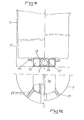
- Figures 1 and 2 of the accompanying drawings show, by way of example, a device for the automatic reloading of sachets in containers, which essentially consists of a means 1 for guiding and distributing sachets 2 mounted in the bottom of the container 3, and by a means 4 for receiving a reserve 5 of sachets 2.
- the means 1 and 4 cooperate to perform in a simple manner the aforementioned functions of guiding and distributing the sachets 2 as well as for receiving the reserve 5.
- the means 1 is advantageously open at the ends and consists of a diametrical slot of an intermediate bottom 6 of the container 3 and the means 4 in the form of a housing extending under said slot.
- the diametrical slot forming the means 1 is advantageously made in one piece with the means 4 during the manufacture of the container 3, said means 4 having a cylinder shape which can be closed at its ends by removable plugs 9, and the slot being advantageously provided with flares 10 for gripping the first bag of the reserve 5.
- the removable plugs make it possible to seal the container 3, which can be particularly advantageous in the case of use of the container as a kitchen trash can, in which possible piercing bag 2 could result in undesirable liquid flow.
- the means 1 is advantageously constituted by a pair of cylinders 12 or bars added to the container 3 and fixed near its bottom by means of blocking elements 13, the reserve 5 of bags being simply disposed under said cylinders 12 or bars on the bottom of the container 3, which forms the receiving means 4.
- Figures 5 and 6 show a consumable embodiment of the invention, in which the means 4 is advantageously constituted by a tray of thermoformed or injected synthetic material, or other material serving simultaneously as packaging for the sale to the reserve 5 of sachets .
- the means 1 consists of a diametrical slot of a cover 16 made of synthetic material or cardboard, integral with the means 4.
- the slot is advantageously provided with one or more flares 10 for gripping the first bag of the reserve 5.
- the bottom of the means 4 is provided with bosses or other shaped elements serving as locations for receiving adhesive pads of the "double-sided" type 17 for its fixing in the bottom of the container 3.
- Figure 7 also shows a consumable variant of the device according to the invention.
- an intermediate bottom 6, in the form of a grid, but which may be full, is provided with the means 1 in the form of a diametrical slot.
- Four peripheral legs 17 ', deformable, in the shape of a "U”, and provided with pins 18 allow the positioning and the maintenance of the intermediate bottom 6 relative to the container 3, above the reserve 5 of sachets.
- Additional feet 19 or ribs can, if necessary, improve the rigidity of the bottom 6, and, in this case, advantageously serve as a housing 4 with the bottom of the container 3 of the reserve of sachets 5.
- the device for the automatic reloading of sachets in receptacles constituted by a means for guiding and distributing sachets 2, and by means 4 'for receiving a reserve 5 of sachets 2, which cooperates with the means l', is characterized in that it is attached to the bottom of an existing container 3 'so amo- v ible, and in that it can be adapted in shape and dimension to the shape and size of the bottom of said vessel 3 '.
- the device according to the invention can be simply placed on the bottom of the container 3 ′, its retention being ensured by its own weight.
- the means 1 ′ for guiding and distributing sachets and the means 4 ′ for receiving a reserve 5 are integral with each other and consist of an element 21 in two parts guided in a body of reception 20 with the possibility of sliding ( Figures 8 and 10).
- This embodiment allows the device to be adapted to containers 3 ′ of different dimensions, by simple sliding movement of the parts of the element 21 in the direction of their spacing or their bringing together (FIGS. 8 and 10).
- the parts of the element 21 are produced, either by extrusion and debitage, or even by injection. In the latter case, the end of the projecting parts of the body 20 can be closed and thus protect the reserve 5. In the case of an extrusion, the parts of the element 21 can be provided with separable sections according to primers of break.
- the receiving body 20 is advantageously produced by extrusion and cutting to length and comprises longitudinal housings 22, which can be filled with ballast 23 and closed by means of plugs 24 of corresponding shape, or into which bars can be introduced.
- ballast 25 advantageously telescopic.
- the use of such bars 25 allows the device to be adapted to the shape and size of the bottom of the container 3 '.
- ballasting allows an improvement in the maintenance of the device in the container 3 '.
- the means 1 ′ for guiding and distributing sachets and the means 4 ′ for receiving a reserve of sachets are formed directly by the reception body 20, which is produced in two connected parts between them by removable intermediate elements 20 'cooperating by form linkage, or which is produced by molding with prediction of break points (not shown) for their adaptation to the dimensions of the container 3'.
- This embodiment of the body 20 makes it possible, by removing or inserting one or more intermediate elements 20 ′, or by breaking along a break point in the case of an embodiment by molding, to adapt the body 20 to the internal dimensions of the container 3 ', the means 1 1 being preferably in the form of a slot open at the ends.
- Figures 11 and 12 show another alternative embodiment of the invention, in which the device consists of a receptacle 26 having at least one longitudinal housing 27 open at the ends forming the means 4 'for receiving a reserve 5 of bags 2, this housing being closed by two covers 28, removable or not, the adjacent edges of which form the guide and distribution means, and lugs 29 extend radially on the periphery of the receptacle 26, these lugs 29 being provided of benchmarks or of primers of rupture 29 ′ allowing their shortening.
- the device can be adapted to the dimensions of the bottom of the container 3 ′ (FIG. 12).
- the receptacle 26 is provided, on both sides of the housing 27, with a compartment 30 intended for the reception of a ballast and closed simultaneously with the housing 27 each by a cover 28 ( Figures 11 and 12).
- Figures 13 to 15 show another alternative embodiment of the invention, in which the means 1 and 4 'are formed directly by a single body 31 having a base 32 for positioning on the bottom of a container 3, this base being provided with radial lugs 33 provided with markers or rupture initiators 34.
- the base 32 is provided with either lateral chambers 35 (FIG. 14 on the left) which can be filled with a ballast and each closed by a cover 36, or, in lateral housings 37, inserts in the form of metal rods 38 mounted by snap-fastening in elastic clamps 39 integral with the base 32.
- the radial lugs 29 or 33 can advantageously be made of an elastically deformable material such as rubber, synthetic rubber, or the like. Such an embodiment allows automatic adaptation of the device to the dimensions of the bottom of a container 3 ′ by simple deformation.
- the device is fixed to the bottom of the container 3 ′, either by means of suction cups integral with its lower face, or by means of an annex fixing device mounted on said bottom of the container 3 'in a removable or final manner and allowing the support of the base or the body of the device by form cooperation.
- the invention it is possible to equip containers, in particular kitchen or bathroom trash cans, or paper baskets with an automatic bag reloading device integrated into the containers, or attached to them .
- the sachets can be extracted automatically after each withdrawal of the previous filled sachet, the separation between the ends of said sachets being carried out during this withdrawal.
Landscapes
- Engineering & Computer Science (AREA)
- Mechanical Engineering (AREA)
- Packages (AREA)
Abstract
Description
- La présente invention concerne le domaine des équipements ménagers ou de bureaux, en particulier des poubelles de cuisines ou de salles de bains et des paniers à papier, et a pour objet un dispositif pour le rechargement automatique de sachets dans des récipients.
- Actuellement, les poubelles, paniers à papier, et autres récipients de ce type à usage domestique ou de bureaux, sont généralement équipés de sachets amovibles en matière synthétique de dimensions appropriées aux dimensions desdits récipients. Ces sachets amovibles sont destinés à être fermés par un lien après leur remplissage et à être déposés dans des poubelles ou conteneurs à vidange périodique.
- Ces poubelles et paniers connus présentent, cependant, l'inconvénient de nécessiter, à chaque retrait d'un sachet rempli, le remplacement de ce dernier par un sachet généralement conditionné de manière arrachable sur un rouleau disposé dans une réserve. Ainsi, ledit sachet est arraché du rouleau à un endroit donné et est placé dans son récipient éventuellement à un autre endroit, de sorte qu'un remplacement d'un sachet plein nécessite plusieurs opérations et déplacements. En outre, un changement de sachet par une personne non avertie des endroits de rangement usuels de la réserve de sachets peut s'avérer impossible à effectuer.
- La présente invention a pour but de pallier ces inconvénients.
- Elle a, en effet,pour objet un dispositif pour le rechargement automatique de sachets dans des récipients, essentiellement constitué par un moyen de guidage et de distribution de sachets, sous forme d'une fente diamétrale, monté dans le fond du récipient, et par un moyen de réception d'une réserve de sachets coopérant avec ledit moyen de guidage et de distribution, caractérisé en ce que la fente diamétrale formant le moyen de guidage et de distribution est avantageusement ouverte aux extrémités et est constituée en une seule pièce avec le moyen de réception lors de la fabrication du récipient, ledit moyen de réception présentant une forme de cylindre pouvant être fermé à ses extrémités par des bouchons amovibles.
- Conformément à une caractéristique de l'invention, le dispositif, constitué par un moyen de guidage et de distribution de sachets, et par un moyen de réception d'une réserve de sachets coopérant avec le moyen de guidage et de distribution, est caractérisé en ce qu'il est rapporté sur le fond d'un récipient existant de manière amovible, et en ce qu'il est adaptable en forme et en dimension aux forme et dimension du fond du récipient.
- L'invention sera mieux comprise grâce à la description ci-après, qui se rapporte à des modes de réalisation préférés, donnés à titre d'exemples non limitatifs, et expliqués avec référence aux dessins schématiques annexés, dans lesquels :
- la figure 1 est une vue en élévation latérale et en coupe d'un récipient équipé du dispositif conforme à l'invention
- la figure 2 est une vue en plan suivant la figure 1 ;
- les figures 3 et 4 représentent, en des vues analogues aux figures 1 et 2 une variante de réalisation de l'invention ;
- la figure 5 est une vue en élévation latérale et en coupe d'un autre dispositif conforme à l'invention ;
- la figure 6 est une vue cavalière suivant la figure 5 ;
- la figure 7 est une vue cavalière d'un autre dispositif conforme à l'invention ;
- la figure 8 est une vue en perpective d'uneva- riante de réalisation de l'invention ;
- la figure 9 est une vue en élévation latérale du dispositif suivant la figure 8, en deux demi-vues présentant chacune ledit dispositif dans un récipient de diamètre de fond différent ;
- la figure 10 est une vue en plan suivant la figure 9 ;
- la figure 11 est une vue analogue à la figure 9, d'une variante de réalisation du dispositif conforme à l'invention ;
- la figure 12 est une vue en plan suivant la figure 11 ;
- la figure 13 est une demi-vue en élévation frontale et en coupe d'une autre variante de réalisation du dispositif conforme à l'invention ;
- la figure 14 est une vue en élévation latérale et en coupe de la figure 13, et.
- la figure 15 est une vue partielle en plan suivant la figure 13.
- Les figures 1 et 2 des dessins annexés représentent, à titre d'exemple, un dispositif pour le rechargement automatique de sachets dans des récipients, qui est essentiellement constitué par un moyen 1 de guidage et de distribution de sachets 2 monté dans le fond du récipient 3, et par un moyen 4 de réception d'une réserve 5 de sachets 2. Les moyens 1 et 4 coopèrent pour assurer de manière simple les fonctions précitées de guidage et de distribution des sachets 2 ainsi que de réception de la réserve 5.
- Le moyen 1 est avantageusement ouvert aux extrémités et est constitué par une fente diamétrale d'un fond intermédiaire 6 du récipient 3 et le moyen 4 sous forme d'un logement s'étendant sous ladite fente.
- Conformément à l'invention, la fente diamétrale formant le moyen 1 est avantageusement constituée en une seule pièce avec le moyen 4 lors de la fabrication du récipient 3, ledit moyen 4 présentant une forme de cylindre pouvant être fermé à ses extrémités par des bouchons amovibles 9, et la fente étant avantageusement munie d'évasements 10 pour la préhension du premier sachet de la réserve 5.
- Les bouchons amovibles permettent d'assurer l'étanchéité du récipient 3, ce qui peut être particulièrement intéressant dans le cas d'usage du récipient comme poubelle de cuisine, dans laquelle un percement éventuel du sachet 2 pourrait avoir pour conséquence un écoulement indésirable de liquide.
- Selon une autre variante de réalisation de l'invention, et comme le montrent les figures 3 et 4, le moyen 1 est avantageusement constitué par une paire de cylindres 12 ou de barres rapportés dans le récipient 3 et fixés près de son fond au moyen d'éléments de blocage 13, la réserve 5 de sachets étant simplement disposée sous lesdits cylindres 12 ou barres sur le fond du récipient 3, qui forme le moyen 4 de réception.
- Les figures 5 et 6 représentent une variante consommable de réalisation de l'invention, dans laquelle le moyen 4 est avantageusement constitué par une barquette en matière synthétique thermoformée ou injectée, ou autre matériau servant simultanément de conditionnement pour la vente à la réserve 5 de sachets. Le moyen 1 est constitué par une fente diamétrale d'un couvercle 16 en matière synthétique ou en carton, solidaire du moyen 4. La fente est avantageusement munie d'un ou de plusieurs évasements 10 pour la préhension du premier sachet de la réserve 5. Le fond du moyen 4 est muni de bossages ou autres éléments de forme servant d'emplacements de réception de pastilles adhésives du type "double face" 17 pour sa fixation dans le fond du récipient 3.
- La figure 7 représente également une variante consommable du dispositif conforme à l'invention. Dans ce mode de réalisation, un fond intermédiaire 6, sous forme de grille, mais pouvant être plein, est muni du moyen 1 sous forme d'une fente diamétrale. Quatre pattes périphériques 17', déformables, en forme de "U", et munies de picots 18 permettent le positionnement et le maintien du fond intermédiaire 6 par rapport au récipient 3, au-dessus de la réserve 5 de sachets. Des pieds supplémentaires 19 ou des nervures peuvent, si nécessaire, améliorer la rigidité du fond 6, et, dans ce cas, servir avantageusement de logement 4 avec le fond du récipient 3 de la réserve de sachets 5.
- Conformément à une autre variante de réalisation de l'invention, et comme le montrent, à titre d'exemples, les figures 8 à 15 des dessins annexés, le dispositif pour le rechargement automatique de sachets dans des récipients, constitués par un moyen l' de guidage et de distribution de sachets 2, et par un moyen 4' de réception d'une réserve 5 de sachets 2, qui coopère ,avec le moyen l', est caractérisé en ce qu'il est rapporté sur le fond d'un récipient existant 3' de manière amo- vible, et en ce qu'il peut être adapté en forme et en dimension à la forme et à la dimension du fond dudit récipient 3'.
- Le dispositif selon l'invention peut être simplement posé sur le fond du récipient 3' son maintien étant assuré par son poids propre.
- Conformément à une caractéristique de l'invention, le moyen l' de guidage et de distribution de sachets et le moyen 4' de réception d'une réserve 5 sont solidaires entre eux et constitués par un élément 21 en deux parties guidées dans un corps de réception 20 avec possibilité de coulissement (figures 8 et 10). Ce mode de réalisation permet l'adaptation du dispositif à des récipients 3' de dimensions différentes, par simple déplacement de coulissement des parties de l'élément 21 dans le sens de leur écartement ou de leur rapprochement (figures 8 et 10).
- Les parties de l'élément 21 sont réalisées, soit par extrusion et débitage, soit encore par injection. Dans ce dernier cas, l'extrémité des parties en saillie du corps 20 peut être fermée et protéger ainsi la réserve 5. Dans le cas d'une extrusion, les parties de l'élément 21 peuvent être pourvues de tronçons séparables suivant des amorces de cassure.
- Le corps de réception 20 est avantageusement réalisé par extrusion et débitage à la longueur et comporte des logements longitudinaux 22, pouvant être remplis d'un lest 23 et obturés au moyen de bouchons 24 de forme correspondante, ou dans lesquels peuvent être introduites des barres de lestage 25, avantageusement télescopiques. L'utilisation de telles barres 25 permet l'adaptation du dispositif à la forme et à la dimension du fond du récipient 3'. En outre, un tel lestage permet une amélioration du maintien du dispositif dans le récipient 3'.
- Selon une autre caractéristique de l'invention, le moyen l' de guidage et de distribution de sachets et le moyen 4' de réception d'une réserve de sachets sont constitués directement par le corps de réception 20, qui est réalisé en deux parties reliées entre elles par des éléments intermédiaires amovibles 20' coopérant par liaison de forme, ou qui est réalisé par moulage avec prévision d'amorces de cassure (non représentées) pour leur adaptation aux dimensions du récipient 3'. Ce mode de réalisation du corps 20 permet, par enlèvement ou insertion d'un ou de plusieurs éléments intermédiaires 20', ou par cassure le long d'une amorce de cassure dans le cas d'une réalisation par moulage, d'adapter le corps 20 aux dimensions intérieures du récipient 3', le moyen 11 étant, de préférence, sous forme d'une fente ouverte aux extrémités.
- Les figures 11 et 12 représentent une autre variante de réalisation de l'invention, dans laquelle le dispositif est constitué par un réceptacle 26 présentant au moins un logement longitudinal 27 ouvert aux extrémités formant le moyen 4' de réception d'une réserve 5 de sachets 2, ce logement étant fermé par deux couvercles 28, amovibles ou non, dont les bords adjacents forment le moyen l' de guidage et de distribution, et des pattes 29 s'étendent radialement sur la périphérie du réceptacle 26, ces pattes 29 étant munies de repères ou d'amorces de rupture 29' permettant leur raccourcissement. Ainsi, le dispositif peut être adapté aux dimensions du fond du récipient 3' (figure 12).
- Selon une autre caractéristique de l'invention, le réceptacle 26 est pourvu, de part et d'autre du logement 27, d'un compartiment 30 destiné à la réception d'un lest et fermé simultanément avec le logement 27 chacun par un couvercle 28 (figures 11 et 12).
- Les figures 13 à 15 représentent une autre variante de réalisation de l'invention, dans laquelle les moyens l'et 4' sont constitués directement par un corps unique 31 présentant une embase 32 de positionnement sur le fond d'un récipient 3, cette embase étant pourvue de pattes radiales 33 munies de repères ou d'amorces de rupture 34. Pour son maintien sur le fond du récipient 3', l'embase 32 est munie, soit de chambres latérales 35 (figure 14 à gauche) pouvant être remplies d'un lest et fermées chacune par un couvercle 36, soit, dans des logements latéraux 37, d'inserts sous forme de tiges métalliques 38 montées par encliquetage dans des pinces élastiques 39 solidaires de l'embase 32.
- Selon une autre caractéristique de l'invention, les pattes radiales 29 ou 33 peuvent avantageusement être constituées en un matériau élastiquement déformable tel que du caoutchouc, du caoutchouc synthétique, ou autre. Un tel mode de réalisation permet une adaptation automatique du dispositif aux dimensions du fond d'un récipient 3' par simple déformation.
- Conformément à une autre caractéristique de l'invention, le dispositif est fixé sur le fond du récipient 3', soit au moyen de ventouses solidaires de sa face inférieure, soit au moyen d'un dispositif de fixation annexe monté sur ledit fond du récipient 3' de manière démontable ou définitive et permettant le maintien de l'embase ou du corps du dispositif par coopération de forme.
- Grâce à l'invention, il est possible d'équiper des récipients,en particulier des poubelles de cuisines ou de salles de bains, ou des paniers à papier d'un dispositif de rechargement automatique de sachets intégré aux récipients, ou rapporté dans ces derniers. Ainsi, les sachets, généralement conditionnés en rouleau, peuvent être extraits automatiquement après chaque retrait du sachet précédent rempli, la séparation entre les extrémités desdits sachets étant réalisée lors de ce retrait.
- Bien entendu, l'invention n'est pas limitée aux modes de réalisation décrits et représentés aux dessins annexés. Des modifications restent possibles, notamment du point de vue de la constitution des divers éléments, ou par substitution d'équivalents techniques, sans sortir pour autant du domaine de protection de l'invention.
Claims (15)
Priority Applications (1)
| Application Number | Priority Date | Filing Date | Title |
|---|---|---|---|
| AT85440061T ATE44706T1 (de) | 1984-10-22 | 1985-10-21 | Vorrichtung zur automatischen abgabe von beuteln in einem behaelter. |
Applications Claiming Priority (4)
| Application Number | Priority Date | Filing Date | Title |
|---|---|---|---|
| FR8416234 | 1984-10-22 | ||
| FR8416234A FR2572058B1 (fr) | 1984-10-22 | 1984-10-22 | Dispositif pour le rechargement automatique de sachets dans des recipients |
| FR8504004 | 1985-03-15 | ||
| FR8504004A FR2578820B2 (fr) | 1985-03-15 | 1985-03-15 | Dispositif pour le rechargement automatique de sachets dans des recipients |
Publications (2)
| Publication Number | Publication Date |
|---|---|
| EP0179729A1 true EP0179729A1 (fr) | 1986-04-30 |
| EP0179729B1 EP0179729B1 (fr) | 1989-07-19 |
Family
ID=26224217
Family Applications (1)
| Application Number | Title | Priority Date | Filing Date |
|---|---|---|---|
| EP19850440061 Expired EP0179729B1 (fr) | 1984-10-22 | 1985-10-21 | Dispositif pour le rechargement automatique de sachets dans des récipients |
Country Status (2)
| Country | Link |
|---|---|
| EP (1) | EP0179729B1 (fr) |
| DE (1) | DE3571594D1 (fr) |
Cited By (8)
| Publication number | Priority date | Publication date | Assignee | Title |
|---|---|---|---|---|
| EP0313421A3 (fr) * | 1987-10-23 | 1989-05-31 | Roy L. Cortesi | Réceptacle muni d'un dispositif de distribution de sacs de garniture |
| GB2253989A (en) * | 1991-03-27 | 1992-09-30 | Yu Chao Ming | An improved garbage can |
| GB2256186A (en) * | 1991-05-28 | 1992-12-02 | Andrew Pasley | Bag dispenser |
| FR2690426A1 (fr) * | 1992-04-22 | 1993-10-29 | Gerard Danielle | Récipient collecteur muni d'un sac. |
| FR2701250A1 (fr) * | 1993-02-09 | 1994-08-12 | Jia Ying | Poubelle à sachet auto-remplaçant. |
| EP0936158A1 (fr) * | 1998-02-16 | 1999-08-18 | Zag Industries Ltd. | Poubelle avec dispositif pour le réchargement automatique de sachets |
| WO2001008985A3 (fr) * | 1999-08-01 | 2001-06-07 | Borgward Glenn Rolus | Dispositif pour sacs a ordures |
| CN105501751A (zh) * | 2016-01-26 | 2016-04-20 | 福州安佳智电子科技有限公司 | 一种智能垃圾桶及其工作方法 |
Families Citing this family (1)
| Publication number | Priority date | Publication date | Assignee | Title |
|---|---|---|---|---|
| CN104085632B (zh) * | 2014-07-21 | 2017-02-01 | 广州大学 | 智能垃圾桶自动换袋套袋装置及方法 |
Citations (9)
| Publication number | Priority date | Publication date | Assignee | Title |
|---|---|---|---|---|
| FR1570133A (fr) * | 1967-06-08 | 1969-04-28 | ||
| US3451453A (en) * | 1967-09-13 | 1969-06-24 | Republic Molding Corp | Waste receptacle with dispenser for disposable liners |
| FR2124445A1 (fr) * | 1971-02-04 | 1972-09-22 | Observa Ag | |
| US3800503A (en) * | 1972-08-10 | 1974-04-02 | R Maki | Bag dispenser and holder |
| DE2424633A1 (de) * | 1974-05-21 | 1975-12-04 | Rudolf Panthoefer | Vorratspackung fuer plastikbeutel aus schlauchfolie |
| CH601078A5 (en) * | 1977-05-24 | 1978-06-30 | Oscar Friberg | Domestic refuse bin with false bottom |
| WO1981003479A1 (fr) * | 1980-06-02 | 1981-12-10 | Surgical Systems Inc | Recipient a dechets avec sacs de doublage fournis par le fond par des cartouches de sacs de doublage echangeables |
| US4319694A (en) * | 1980-10-14 | 1982-03-16 | Nehrbass Joel M | Refuse receptacle with renewable liners |
| AU537280B2 (en) * | 1980-04-03 | 1984-06-14 | Chiang, Keh-Yeu | Garbage can with plastic bag supplier |
-
1985
- 1985-10-21 EP EP19850440061 patent/EP0179729B1/fr not_active Expired
- 1985-10-21 DE DE8585440061T patent/DE3571594D1/de not_active Expired
Patent Citations (9)
| Publication number | Priority date | Publication date | Assignee | Title |
|---|---|---|---|---|
| FR1570133A (fr) * | 1967-06-08 | 1969-04-28 | ||
| US3451453A (en) * | 1967-09-13 | 1969-06-24 | Republic Molding Corp | Waste receptacle with dispenser for disposable liners |
| FR2124445A1 (fr) * | 1971-02-04 | 1972-09-22 | Observa Ag | |
| US3800503A (en) * | 1972-08-10 | 1974-04-02 | R Maki | Bag dispenser and holder |
| DE2424633A1 (de) * | 1974-05-21 | 1975-12-04 | Rudolf Panthoefer | Vorratspackung fuer plastikbeutel aus schlauchfolie |
| CH601078A5 (en) * | 1977-05-24 | 1978-06-30 | Oscar Friberg | Domestic refuse bin with false bottom |
| AU537280B2 (en) * | 1980-04-03 | 1984-06-14 | Chiang, Keh-Yeu | Garbage can with plastic bag supplier |
| WO1981003479A1 (fr) * | 1980-06-02 | 1981-12-10 | Surgical Systems Inc | Recipient a dechets avec sacs de doublage fournis par le fond par des cartouches de sacs de doublage echangeables |
| US4319694A (en) * | 1980-10-14 | 1982-03-16 | Nehrbass Joel M | Refuse receptacle with renewable liners |
Cited By (9)
| Publication number | Priority date | Publication date | Assignee | Title |
|---|---|---|---|---|
| EP0313421A3 (fr) * | 1987-10-23 | 1989-05-31 | Roy L. Cortesi | Réceptacle muni d'un dispositif de distribution de sacs de garniture |
| GB2253989A (en) * | 1991-03-27 | 1992-09-30 | Yu Chao Ming | An improved garbage can |
| GB2253989B (en) * | 1991-03-27 | 1995-05-17 | Yu Chao Ming | Garbage can |
| GB2256186A (en) * | 1991-05-28 | 1992-12-02 | Andrew Pasley | Bag dispenser |
| FR2690426A1 (fr) * | 1992-04-22 | 1993-10-29 | Gerard Danielle | Récipient collecteur muni d'un sac. |
| FR2701250A1 (fr) * | 1993-02-09 | 1994-08-12 | Jia Ying | Poubelle à sachet auto-remplaçant. |
| EP0936158A1 (fr) * | 1998-02-16 | 1999-08-18 | Zag Industries Ltd. | Poubelle avec dispositif pour le réchargement automatique de sachets |
| WO2001008985A3 (fr) * | 1999-08-01 | 2001-06-07 | Borgward Glenn Rolus | Dispositif pour sacs a ordures |
| CN105501751A (zh) * | 2016-01-26 | 2016-04-20 | 福州安佳智电子科技有限公司 | 一种智能垃圾桶及其工作方法 |
Also Published As
| Publication number | Publication date |
|---|---|
| EP0179729B1 (fr) | 1989-07-19 |
| DE3571594D1 (en) | 1989-08-24 |
Similar Documents
| Publication | Publication Date | Title |
|---|---|---|
| FR2665422A1 (fr) | Montant reglable de support de corbeilles a courrier. | |
| EP0179729B1 (fr) | Dispositif pour le rechargement automatique de sachets dans des récipients | |
| FR2511859A1 (fr) | Distributeur de pate dentifrice | |
| FR2575047A3 (fr) | Support pour instruments a ecrire | |
| FR2750958A1 (fr) | Distributeur de papier comportant une cassette amovible | |
| EP0926080B1 (fr) | Récipient muni d'un dispositif d'extraction automatique d'une paille | |
| FR2572058A1 (fr) | Dispositif pour le rechargement automatique de sachets dans des recipients | |
| FR2850091A1 (fr) | Poubelle adaptee pour le tri selectif | |
| EP1026420A1 (fr) | Support antivibratoire et son procédé de fabrication | |
| EP0030892A1 (fr) | Bac à plantes empilable | |
| FR2601655A1 (fr) | Emballage reutilisable pour caler des objets | |
| EP0147346A1 (fr) | Sachet en matière synthétique souple comportant un élément rigide amovible servant d'élément de bouchage | |
| FR2612501A1 (fr) | Bac pour marc de cafe | |
| EP3795500B1 (fr) | Couvercle étanche pour bac de collecte de déchets | |
| FR2573039A1 (fr) | Nouvel emballage pour le conditionnement de liquides | |
| FR2583020A1 (fr) | Receptacle pour l'emmagasinage, le transport, la presentation et la distribution a l'unite d'objets tels que des pots, paquet constitue du receptacle garni d'objets et ensemble de presentation et de distribution associant plusieurs paquets | |
| FR2612496A1 (fr) | Coiffe de maintien et de transport de deux objets allonges voisins, tels que des bouteilles verticales | |
| FR2836128A1 (fr) | Distributeur de produit fluide | |
| FR2578820A2 (fr) | Dispositif pour le rechargement automatique de sachets dans des recipients | |
| FR2766692A1 (fr) | Bouilloire electrique comportant un bec verseur et un indicateur de niveau de remplissage | |
| FR2758298A1 (fr) | Porte-gobelets, particulierement pour vehicule automobile | |
| EP0051001B1 (fr) | Boîte à produit lessiviel munie d'un entonnoir téléscopique intégré, et machine à laver le linge comprenant une boîte de ce type | |
| FR2744703A1 (fr) | Pot destine a recevoir des produits en vrac | |
| FR2556322A1 (fr) | Emballage pour le conditionnement de liquides | |
| FR2658798A1 (fr) | Dispositif pour l'emballage d'une plante en pot. |
Legal Events
| Date | Code | Title | Description |
|---|---|---|---|
| PUAI | Public reference made under article 153(3) epc to a published international application that has entered the european phase |
Free format text: ORIGINAL CODE: 0009012 |
|
| AK | Designated contracting states |
Kind code of ref document: A1 Designated state(s): AT BE CH DE GB IT LI NL SE |
|
| 17P | Request for examination filed |
Effective date: 19861021 |
|
| 17Q | First examination report despatched |
Effective date: 19870922 |
|
| GRAA | (expected) grant |
Free format text: ORIGINAL CODE: 0009210 |
|
| AK | Designated contracting states |
Kind code of ref document: B1 Designated state(s): AT BE CH DE GB IT LI NL SE |
|
| PG25 | Lapsed in a contracting state [announced via postgrant information from national office to epo] |
Ref country code: SE Free format text: THE PATENT HAS BEEN ANNULLED BY A DECISION OF A NATIONAL AUTHORITY Effective date: 19890719 Ref country code: NL Effective date: 19890719 Ref country code: AT Effective date: 19890719 |
|
| REF | Corresponds to: |
Ref document number: 44706 Country of ref document: AT Date of ref document: 19890815 Kind code of ref document: T |
|
| REF | Corresponds to: |
Ref document number: 3571594 Country of ref document: DE Date of ref document: 19890824 |
|
| ITF | It: translation for a ep patent filed | ||
| PG25 | Lapsed in a contracting state [announced via postgrant information from national office to epo] |
Ref country code: LI Effective date: 19891031 Ref country code: CH Effective date: 19891031 |
|
| GBT | Gb: translation of ep patent filed (gb section 77(6)(a)/1977) | ||
| NLV1 | Nl: lapsed or annulled due to failure to fulfill the requirements of art. 29p and 29m of the patents act | ||
| PLBE | No opposition filed within time limit |
Free format text: ORIGINAL CODE: 0009261 |
|
| STAA | Information on the status of an ep patent application or granted ep patent |
Free format text: STATUS: NO OPPOSITION FILED WITHIN TIME LIMIT |
|
| REG | Reference to a national code |
Ref country code: CH Ref legal event code: PL |
|
| 26N | No opposition filed | ||
| PGFP | Annual fee paid to national office [announced via postgrant information from national office to epo] |
Ref country code: GB Payment date: 19921012 Year of fee payment: 8 |
|
| PGFP | Annual fee paid to national office [announced via postgrant information from national office to epo] |
Ref country code: BE Payment date: 19921029 Year of fee payment: 8 |
|
| ITTA | It: last paid annual fee | ||
| PG25 | Lapsed in a contracting state [announced via postgrant information from national office to epo] |
Ref country code: GB Effective date: 19931021 |
|
| PG25 | Lapsed in a contracting state [announced via postgrant information from national office to epo] |
Ref country code: BE Effective date: 19931031 |
|
| PGFP | Annual fee paid to national office [announced via postgrant information from national office to epo] |
Ref country code: DE Payment date: 19931222 Year of fee payment: 9 |
|
| BERE | Be: lapsed |
Owner name: KUHN FRANCIS Effective date: 19931031 |
|
| GBPC | Gb: european patent ceased through non-payment of renewal fee |
Effective date: 19931021 |
|
| PG25 | Lapsed in a contracting state [announced via postgrant information from national office to epo] |
Ref country code: DE Effective date: 19950701 |