EP0179754A2 - Support pour fixer des enseignes ou similaires - Google Patents
Support pour fixer des enseignes ou similaires Download PDFInfo
- Publication number
- EP0179754A2 EP0179754A2 EP85890260A EP85890260A EP0179754A2 EP 0179754 A2 EP0179754 A2 EP 0179754A2 EP 85890260 A EP85890260 A EP 85890260A EP 85890260 A EP85890260 A EP 85890260A EP 0179754 A2 EP0179754 A2 EP 0179754A2
- Authority
- EP
- European Patent Office
- Prior art keywords
- arm
- holder according
- fixing device
- holder
- connector
- Prior art date
- Legal status (The legal status is an assumption and is not a legal conclusion. Google has not performed a legal analysis and makes no representation as to the accuracy of the status listed.)
- Granted
Links
Images

Classifications
-
- G—PHYSICS
- G09—EDUCATION; CRYPTOGRAPHY; DISPLAY; ADVERTISING; SEALS
- G09F—DISPLAYING; ADVERTISING; SIGNS; LABELS OR NAME-PLATES; SEALS
- G09F3/00—Labels, tag tickets, or similar identification or indication means; Seals; Postage or like stamps
- G09F3/08—Fastening or securing by means not forming part of the material of the label itself
- G09F3/18—Casings, frames or enclosures for labels
- G09F3/20—Casings, frames or enclosures for labels for adjustable, removable, or interchangeable labels
- G09F3/204—Casings, frames or enclosures for labels for adjustable, removable, or interchangeable labels specially adapted to be attached to a shelf or the like
-
- G—PHYSICS
- G09—EDUCATION; CRYPTOGRAPHY; DISPLAY; ADVERTISING; SEALS
- G09F—DISPLAYING; ADVERTISING; SIGNS; LABELS OR NAME-PLATES; SEALS
- G09F3/00—Labels, tag tickets, or similar identification or indication means; Seals; Postage or like stamps
- G09F3/08—Fastening or securing by means not forming part of the material of the label itself
- G09F3/18—Casings, frames or enclosures for labels
- G09F3/20—Casings, frames or enclosures for labels for adjustable, removable, or interchangeable labels
- G09F3/201—Enclosures enveloping completely the labels
Definitions
- the invention relates to a holder for fixing notice boards, price boards, frames for such boards or the like.
- G alen on shelves of storage or Ladenre galen which holder is provided with a connector that with a counterpart provided on the boards or frame can be put together and is designed as part of a bayonet catch, as a plug, as a clamp, as a push button or the like.
- a known holder of the aforementioned type has a resilient bracket which carries in the middle part of a bayonet catch and has further cutting-like ends which can be inserted into the undercut grooves of rails, which often run along the front edge of the shelves in storage and shop shelves are arranged.
- These rails are primarily intended to hold strip-shaped cards which carry information about the goods on the relevant shelf.
- brackets of these known holders are fixed with their cutting edges in the rails and are thus firmly seated on the rails, and it is therefore also the announcement panels or the like which correspond to the bayonet fitting parts present on the brackets Have bayonet lock parts and are thus joined to the brackets, held on the rails.
- the announcement boards cover the part of the rails behind it, and it is practically neither visible nor accessible.
- another known holder which is designed in the manner of a bracket which resiliently encompasses the above-mentioned rails on the top and bottom of the shelves and also carries part of a bayonet catch with which it can be used with notice boards or the like can be put together.
- the aim of the invention is to provide a holder of the type mentioned at the beginning, in which the disadvantages of the known holders are eliminated and which, in particular, despite carrying announcement boards or the like which are arranged in front of the front edge of the shelves, has access to those behind them Boards or similar sections of the front edge of the shelves made possible without difficulty, so that information-carrying cards placed there can be read.
- the holder of the type mentioned above is characterized in that the connector on the free. is arranged resiliently pivotable end of an arm. which in turn has at its other end a fixing device provided for attaching the arm to a shelf.
- the boards connected to such holders or the like which are arranged with the holders in front of the front edge of real shelves, can be easily moved away from the front edge if necessary, so that information carriers placed on the front edge of the shelf shelves are freely accessible.
- the fixing means is formed as Ma g nethalter. This training gives the further advantage. that the holder can be attached to iron shelves very easily, since the magnetic holder adheres well to the shelves without requiring particularly precise manipulation.
- the fixing device may be formed g also useful as an adhesive base, suction cup or Anschraubfuß or Anschraubeinrichtun which formations, in particular wooden also for non-magnetic. Shelves are suitable. Such feet can also be surfaces molded onto the arm.
- a preferred embodiment of the holder according to the invention is characterized in that the free end of the arm can be pivoted resiliently essentially transversely to the adhesive surface of the fixing device on the shelf.
- this arm is advantageously designed to be resiliently flexible. It is advantageous to achieve a compact design and to keep the tipping load of the fixing device, which is designed in particular as a magnetic holder, if the arm near its connection to the fixing device is curved in a meandering or zigzag fashion. A further reduction in the overall length of the arm without sacrificing load-bearing capacity and flexibility can be achieved if it is provided that starting from the connection of the arm with the fixing device, there follow several sections running approximately parallel to the adhesive surface, to which a section running essentially parallel to the adhesive surface Section of the arm follows which leads to the end having the connector.
- connection of the arm with the fixing device is provided on the side of the fixing device facing away from the connector, this measure keeping the load on the fixing device low due to a tilting moment exerted by the arm and thus for a secure fit of the fixing device on the shelves contributes.
- the arm is designed as a two-legged wire bracket. This embodiment ensures a particularly good durability of the holder. You can also achieve a particularly simple coupling of the connector with the announcement boards or the like. If one forms the front end of the wire bracket as a plug that can be inserted into a slot in the frame or the board.
- the arm can also be provided with a pivot point at which a spring is arranged.
- a spring is arranged.
- the fixing device is designed as a magnet holder, it is advantageous if the magnet holder has pole shoes on the adhesive surface which extend in the direction of the extend the connector supporting arm. It is advantageous if the magnet holder has two pairs of pole shoes.
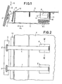
- the holder shown in Fig. 1 has an arm 1 which carries at its free, resiliently pivotable end 2 a connector 3 which is joined to a counterpart 5 arranged on a panel frame 4.
- the connector 3 is designed as one part of a bayonet lock, and the counterpart 5 as the other part of this bayonet lock. Instead of such a connection, the connector can also be designed as a plug, as a clamp, as a push button or the like.
- the arm 1 in turn has at its other end 18 a fixing device, which in the present case as Magnet holder 6 is formed.
- the shelf shelf 9 carries on its front a rail 10, into which cards 11 can be inserted, which contain information about goods which are stored at this point on the shelf 9.
- cards 11 In order to be able to view this information or to be able to scan it with a scanner device, or to gain access to the rail arranged on the front edge 12 of the shelf 9, the person can take notice boards.
- Provided frame 4 are pressed down in the direction of arrow 14, the free end 2 of the arm 1 springing out accordingly. After releasing the frame 4, the arm 1 springs back into its position shown in FIG. 1.
- the magnet holder 6 has pole shoes 16 on the adhesive surface 15, which extend in the direction of the arm 1 carrying the connector. Two pairs of such pole shoes 16 are provided, between which permanent magnets 8 are arranged.
- the free end 2 of the arm 1 is essentially resiliently pivotable transversely to the adhesive surface 15 of the magnet holder 6.
- the arm 1 When in the Fi g . 1 to 3 shown embodiment, the arm 1 itself is resiliently flexible and bent in a meandering manner in the vicinity of its connection to the magnet holder 6.
- the arm 1 is with the magnet holder facing away from the connector 3 Side 17 of the magnet holder connected, and for this purpose the end 18 of the arm 1 is inserted into a pocket 20 provided on the magnet holder 6.
- the arm 1 is bent at its end 2 carrying the connector 3 approximately transversely to the adhesive surface 15 of the magnet holder 6. This configuration results in a good fit of the connection between the arm 1 and the announcement boards or board frames and also facilitates manipulation when mounting the holder.
- the arm 1 is formed in two parts, one part 25 being fixed to the magnet holder 6 and the other part 26 carrying the connector 3.
- the two parts 25, 26 of the arm 1 are joined together at a pivot point 27, and it is on This pivot point 27 is arranged a spring 28 which tries to bring the two parts 25, 26 closer to one another in the direction of the arrow 29.
- the spring 28 is designed as a spiral spiral spring. To a panel arranged on the connector 3 or deral. to move away from the rail 10 arranged on the front of a shelf, this panel is pivoted forward against the force of the spring 28 in the direction of the arrow 30.
- the arm 1 is designed in the form of a two-legged wire bracket 32. At the rear end 33, this wire bracket merges into two spiral springs 34, followed by legs 35, which are inserted into corresponding bores in the housing 7 of the magnet holder 6.
- the front end 36 of the wire bracket is bent upwards and shaped into a plug which can be inserted into a slot in the frame or the panel to be carried.
- This connector 3, which is designed as a plug, has two indentations 37 which can cooperate with corresponding constrictions in the slot of the frame or the panel and which in a simple manner provide a very secure hold.
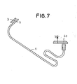
- the arm 1 which is analogous to the embodiment shown in Figs. 1 to 3 itself resiliently flexible and bent meandering near its connection to the fixing device, is attached to an adhesive foot 39 which forms the fixing device.
- This design of the fixing device allows the holder to be easily attached to non-magnetic, in particular wooden, shelf shelves.
- the adhesive foot 39 has a self-adhesive pad 40, which serves to form the adhesive bond between the adhesive foot and the shelf.
- the resiliently flexible arm 1 is in its relaxed position in FIG. 7 shown; the free end 2 of the arm 1 or the connector provided there is loaded with an announcement board or the like.
- the end 2 can move somewhat downward, so that the arm 1 assumes a shape, for example, as shown in FIGS Fi g . 1 and 6 is shown.
- the arm 1 can also be pressed down by resting on a price rail or the like.
- this arm in order to achieve a favorable, constant bending behavior of the arm 1 over a long period of time, one can advantageously form this arm as an injection-molded plastic part.
Landscapes
- Physics & Mathematics (AREA)
- General Physics & Mathematics (AREA)
- Engineering & Computer Science (AREA)
- Theoretical Computer Science (AREA)
- Supports Or Holders For Household Use (AREA)
- Clamps And Clips (AREA)
- Adhesives Or Adhesive Processes (AREA)
- Laminated Bodies (AREA)
Priority Applications (1)
| Application Number | Priority Date | Filing Date | Title |
|---|---|---|---|
| AT85890260T ATE48712T1 (de) | 1984-10-26 | 1985-10-21 | Halter zur fixierung von ankuendigungstafeln oder dergl. |
Applications Claiming Priority (2)
| Application Number | Priority Date | Filing Date | Title |
|---|---|---|---|
| DE8431521U | 1984-10-26 | ||
| DE8431521 | 1984-10-26 |
Publications (3)
| Publication Number | Publication Date |
|---|---|
| EP0179754A2 true EP0179754A2 (fr) | 1986-04-30 |
| EP0179754A3 EP0179754A3 (en) | 1987-08-05 |
| EP0179754B1 EP0179754B1 (fr) | 1989-12-13 |
Family
ID=6772117
Family Applications (1)
| Application Number | Title | Priority Date | Filing Date |
|---|---|---|---|
| EP85890260A Expired EP0179754B1 (fr) | 1984-10-26 | 1985-10-21 | Support pour fixer des enseignes ou similaires |
Country Status (3)
| Country | Link |
|---|---|
| EP (1) | EP0179754B1 (fr) |
| AT (1) | ATE48712T1 (fr) |
| DE (1) | DE3574790D1 (fr) |
Cited By (3)
| Publication number | Priority date | Publication date | Assignee | Title |
|---|---|---|---|---|
| GB2333693A (en) * | 1998-01-28 | 1999-08-04 | Ppe Ltd | Detachable display mounting for shelving units |
| EP0965971A3 (fr) * | 1998-06-17 | 2000-04-12 | Mages, Daniela | Dispositif de montage d'une carte d'informations |
| US20250037615A1 (en) * | 2022-04-27 | 2025-01-30 | Boe Technology Group Co., Ltd. | Installation Structure and Electronic Device |
Family Cites Families (8)
| Publication number | Priority date | Publication date | Assignee | Title |
|---|---|---|---|---|
| GB323232A (en) * | 1928-09-26 | 1929-12-27 | Abdulla & Company Ltd | A new or improved display stand or support |
| US2942831A (en) * | 1954-10-21 | 1960-06-28 | Personal Products Corp | Display device |
| FR1320420A (fr) * | 1962-04-18 | 1963-03-08 | Panneau support présentoir | |
| US3784027A (en) * | 1970-01-09 | 1974-01-08 | Uni Syst Inc | Display device and method of merchandising and inventory control |
| US3889408A (en) * | 1971-08-11 | 1975-06-17 | Burton E Offner | Stock shelf layout indicators |
| DE2715396A1 (de) * | 1977-04-06 | 1978-10-12 | Herbert Mueller | Aufhaengehaken fuer selbstbedienungs- packungen, insbesondere lochplattenhaken |
| US4405051A (en) * | 1980-05-19 | 1983-09-20 | Trion Industries, Inc. | Merchandise hook |
| DE8523986U1 (de) * | 1985-08-21 | 1985-10-24 | Tiedemann, Roman, Wien | Einrichtung zur Anbringung von Ankündigungstafeln |
-
1985
- 1985-10-21 AT AT85890260T patent/ATE48712T1/de not_active IP Right Cessation
- 1985-10-21 EP EP85890260A patent/EP0179754B1/fr not_active Expired
- 1985-10-21 DE DE8585890260T patent/DE3574790D1/de not_active Expired - Lifetime
Cited By (4)
| Publication number | Priority date | Publication date | Assignee | Title |
|---|---|---|---|---|
| GB2333693A (en) * | 1998-01-28 | 1999-08-04 | Ppe Ltd | Detachable display mounting for shelving units |
| GB2333693B (en) * | 1998-01-28 | 2001-07-18 | Ppe Ltd | Display mounting |
| EP0965971A3 (fr) * | 1998-06-17 | 2000-04-12 | Mages, Daniela | Dispositif de montage d'une carte d'informations |
| US20250037615A1 (en) * | 2022-04-27 | 2025-01-30 | Boe Technology Group Co., Ltd. | Installation Structure and Electronic Device |
Also Published As
| Publication number | Publication date |
|---|---|
| EP0179754B1 (fr) | 1989-12-13 |
| ATE48712T1 (de) | 1989-12-15 |
| EP0179754A3 (en) | 1987-08-05 |
| DE3574790D1 (de) | 1990-01-18 |
Similar Documents
| Publication | Publication Date | Title |
|---|---|---|
| EP0179754B1 (fr) | Support pour fixer des enseignes ou similaires | |
| DE8431521U1 (de) | Halter zur Fixierung von Ankündigungstafeln od. dgl. | |
| EP1927097B1 (fr) | Badge | |
| DE1913954U (de) | Halter fuer teppichmuster. | |
| AT394913B (de) | Einrichtung zur loesbaren befestigung von an lagerbehaeltern, lagerregalen, ladenmoebeln od. dgl. anzubringenden anzeigeschildern | |
| DE3701807C2 (fr) | ||
| DE69017917T3 (de) | Schau- oder verkaufsregal zur anwendung in regalsystemen. | |
| EP0764929B1 (fr) | Dispositif d'affichage d'informations relatives au prix et/ou en produit | |
| DE202022101273U1 (de) | Vorrichtung zur Fixierung eines elektronischen Preisschildes, Warenregal und Regalpreisleiste | |
| DE202017100195U1 (de) | Systeme und Vorrichtungen zur Verbindung von Regalen | |
| DE3420608C2 (de) | Vorrichtung zur Halterung und Präsentation von in SB-Verpackungen befindlichen Waren | |
| EP0448192B1 (fr) | Badge attaché avec une épingle | |
| DE202010004155U1 (de) | Schau- und/oder Schreibtafel | |
| DE2835458C2 (de) | Seifenhalter | |
| DE9208400U1 (de) | Anzeige- und Reklamemittel | |
| DE69401869T2 (de) | Schuh-Auflageeinrichtung auf Skis | |
| DE102010012678B4 (de) | Schau- und/oder Schreibtafel | |
| DE2624183A1 (de) | Befestigungselement zur befestigung von platten und streifen an drahtkoerben | |
| EP1129651B1 (fr) | Bloc de support pour un dispositif de stockage et de présentation de bracelets de montre | |
| DE2144563C3 (de) | Regalkonsole Wilke, Heinrich; Wilke, Rudolf, Dipl.-Wirtsch.-Ing.; 3548 Arolsen | |
| DE8602293U1 (de) | Bilderrahmenklammer | |
| DE838575C (de) | Schreibunterlage | |
| DE1816046U (de) | Tragvorrichtung fuer ladenregale u. dgl. | |
| DE1985644U (de) | Luesterklemmengehaeuse. | |
| CH680173A5 (fr) |
Legal Events
| Date | Code | Title | Description |
|---|---|---|---|
| PUAI | Public reference made under article 153(3) epc to a published international application that has entered the european phase |
Free format text: ORIGINAL CODE: 0009012 |
|
| AK | Designated contracting states |
Kind code of ref document: A2 Designated state(s): AT BE CH DE FR GB IT LI LU NL SE |
|
| PUAL | Search report despatched |
Free format text: ORIGINAL CODE: 0009013 |
|
| AK | Designated contracting states |
Kind code of ref document: A3 Designated state(s): AT BE CH DE FR GB IT LI LU NL SE |
|
| RAP1 | Party data changed (applicant data changed or rights of an application transferred) |
Owner name: ESSELTE PENDAFLEX GESELLSCHAFT M.B.H. |
|
| RIN1 | Information on inventor provided before grant (corrected) |
Inventor name: TIEDEMANN, ROMAN |
|
| 17P | Request for examination filed |
Effective date: 19870828 |
|
| 17Q | First examination report despatched |
Effective date: 19890309 |
|
| GRAA | (expected) grant |
Free format text: ORIGINAL CODE: 0009210 |
|
| AK | Designated contracting states |
Kind code of ref document: B1 Designated state(s): AT BE CH DE FR GB IT LI LU NL SE |
|
| PG25 | Lapsed in a contracting state [announced via postgrant information from national office to epo] |
Ref country code: IT Free format text: LAPSE BECAUSE OF FAILURE TO SUBMIT A TRANSLATION OF THE DESCRIPTION OR TO PAY THE FEE WITHIN THE PRESCRIBED TIME-LIMIT;WARNING: LAPSES OF ITALIAN PATENTS WITH EFFECTIVE DATE BEFORE 2007 MAY HAVE OCCURRED AT ANY TIME BEFORE 2007. THE CORRECT EFFECTIVE DATE MAY BE DIFFERENT FROM THE ONE RECORDED. Effective date: 19891213 |
|
| REF | Corresponds to: |
Ref document number: 48712 Country of ref document: AT Date of ref document: 19891215 Kind code of ref document: T |
|
| ET | Fr: translation filed | ||
| GBT | Gb: translation of ep patent filed (gb section 77(6)(a)/1977) | ||
| REF | Corresponds to: |
Ref document number: 3574790 Country of ref document: DE Date of ref document: 19900118 |
|
| PLBE | No opposition filed within time limit |
Free format text: ORIGINAL CODE: 0009261 |
|
| STAA | Information on the status of an ep patent application or granted ep patent |
Free format text: STATUS: NO OPPOSITION FILED WITHIN TIME LIMIT |
|
| PG25 | Lapsed in a contracting state [announced via postgrant information from national office to epo] |
Ref country code: LI Effective date: 19901031 Ref country code: CH Effective date: 19901031 Ref country code: LU Free format text: LAPSE BECAUSE OF NON-PAYMENT OF DUE FEES Effective date: 19901031 |
|
| 26N | No opposition filed | ||
| REG | Reference to a national code |
Ref country code: CH Ref legal event code: PL |
|
| EAL | Se: european patent in force in sweden |
Ref document number: 85890260.4 |
|
| PGFP | Annual fee paid to national office [announced via postgrant information from national office to epo] |
Ref country code: BE Payment date: 19961212 Year of fee payment: 12 |
|
| PG25 | Lapsed in a contracting state [announced via postgrant information from national office to epo] |
Ref country code: BE Free format text: LAPSE BECAUSE OF NON-PAYMENT OF DUE FEES Effective date: 19971031 |
|
| BERE | Be: lapsed |
Owner name: ESSELTE PENDAFLEX G.M.B.H. Effective date: 19971031 |
|
| REG | Reference to a national code |
Ref country code: GB Ref legal event code: IF02 |
|
| PGFP | Annual fee paid to national office [announced via postgrant information from national office to epo] |
Ref country code: SE Payment date: 20021004 Year of fee payment: 18 |
|
| PGFP | Annual fee paid to national office [announced via postgrant information from national office to epo] |
Ref country code: AT Payment date: 20021011 Year of fee payment: 18 |
|
| PGFP | Annual fee paid to national office [announced via postgrant information from national office to epo] |
Ref country code: GB Payment date: 20021016 Year of fee payment: 18 |
|
| PGFP | Annual fee paid to national office [announced via postgrant information from national office to epo] |
Ref country code: DE Payment date: 20021024 Year of fee payment: 18 |
|
| PG25 | Lapsed in a contracting state [announced via postgrant information from national office to epo] |
Ref country code: GB Free format text: LAPSE BECAUSE OF NON-PAYMENT OF DUE FEES Effective date: 20031021 Ref country code: AT Free format text: LAPSE BECAUSE OF NON-PAYMENT OF DUE FEES Effective date: 20031021 |
|
| PG25 | Lapsed in a contracting state [announced via postgrant information from national office to epo] |
Ref country code: SE Free format text: LAPSE BECAUSE OF NON-PAYMENT OF DUE FEES Effective date: 20031022 |
|
| PG25 | Lapsed in a contracting state [announced via postgrant information from national office to epo] |
Ref country code: DE Free format text: LAPSE BECAUSE OF NON-PAYMENT OF DUE FEES Effective date: 20040501 |
|
| EUG | Se: european patent has lapsed | ||
| GBPC | Gb: european patent ceased through non-payment of renewal fee |
Effective date: 20031021 |
|
| PGFP | Annual fee paid to national office [announced via postgrant information from national office to epo] |
Ref country code: FR Payment date: 20041020 Year of fee payment: 20 |
|
| PGFP | Annual fee paid to national office [announced via postgrant information from national office to epo] |
Ref country code: NL Payment date: 20041229 Year of fee payment: 20 |
|
| PG25 | Lapsed in a contracting state [announced via postgrant information from national office to epo] |
Ref country code: NL Free format text: LAPSE BECAUSE OF EXPIRATION OF PROTECTION Effective date: 20051021 |
|
| NLV7 | Nl: ceased due to reaching the maximum lifetime of a patent |
Effective date: 20051021 |