EP0179893B1 - Kammerverschluss für gewehre - Google Patents
Kammerverschluss für gewehre Download PDFInfo
- Publication number
- EP0179893B1 EP0179893B1 EP85902696A EP85902696A EP0179893B1 EP 0179893 B1 EP0179893 B1 EP 0179893B1 EP 85902696 A EP85902696 A EP 85902696A EP 85902696 A EP85902696 A EP 85902696A EP 0179893 B1 EP0179893 B1 EP 0179893B1
- Authority
- EP
- European Patent Office
- Prior art keywords
- bolt
- guide sleeve
- firing pin
- guide
- rifle
- Prior art date
- Legal status (The legal status is an assumption and is not a legal conclusion. Google has not performed a legal analysis and makes no representation as to the accuracy of the status listed.)
- Expired
Links
- 238000010304 firing Methods 0.000 claims abstract description 49
- 230000000295 complement effect Effects 0.000 claims description 2
- 238000012423 maintenance Methods 0.000 description 3
- 238000004519 manufacturing process Methods 0.000 description 3
- 230000004308 accommodation Effects 0.000 description 1
- 238000003754 machining Methods 0.000 description 1
Images

Classifications
-
- F—MECHANICAL ENGINEERING; LIGHTING; HEATING; WEAPONS; BLASTING
- F41—WEAPONS
- F41A—FUNCTIONAL FEATURES OR DETAILS COMMON TO BOTH SMALLARMS AND ORDNANCE, e.g. CANNONS; MOUNTINGS FOR SMALLARMS OR ORDNANCE
- F41A3/00—Breech mechanisms, e.g. locks
- F41A3/12—Bolt action, i.e. the main breech opening movement being parallel to the barrel axis
- F41A3/14—Rigid bolt locks, i.e. having locking elements rigidly mounted on the bolt or bolt handle and on the barrel or breech-housing respectively
- F41A3/16—Rigid bolt locks, i.e. having locking elements rigidly mounted on the bolt or bolt handle and on the barrel or breech-housing respectively the locking elements effecting a rotary movement about the barrel axis, e.g. rotating cylinder bolt locks
- F41A3/18—Rigid bolt locks, i.e. having locking elements rigidly mounted on the bolt or bolt handle and on the barrel or breech-housing respectively the locking elements effecting a rotary movement about the barrel axis, e.g. rotating cylinder bolt locks hand-operated
- F41A3/22—Rigid bolt locks, i.e. having locking elements rigidly mounted on the bolt or bolt handle and on the barrel or breech-housing respectively the locking elements effecting a rotary movement about the barrel axis, e.g. rotating cylinder bolt locks hand-operated the locking being effected by rotating the operating handle or lever transversely to the barrel axis
-
- F—MECHANICAL ENGINEERING; LIGHTING; HEATING; WEAPONS; BLASTING
- F41—WEAPONS
- F41A—FUNCTIONAL FEATURES OR DETAILS COMMON TO BOTH SMALLARMS AND ORDNANCE, e.g. CANNONS; MOUNTINGS FOR SMALLARMS OR ORDNANCE
- F41A17/00—Safety arrangements, e.g. safeties
- F41A17/30—Multiple safeties, i.e. one safety element acting on at least one element of the firing mechanism and at least one other element of the gun, e.g. the moving barrel
- F41A17/32—Multiple safeties, i.e. one safety element acting on at least one element of the firing mechanism and at least one other element of the gun, e.g. the moving barrel the other element being the breech-block or bolt
Definitions
- the present invention relates to a rifle bolt mechanism of the turning bolt action type where a bolt, which is provided with a handle, along the major part of its length is mounted rotatably but axially undisplaceably in a guide sleeve, which is intended to guide the bolt in a breech mechanism, and where a firing pin connected with a firing pin nut cooperates with the bolt, which at its forward end is provided with locking abutments for fixing the bolt in the firing position in the breech mechanism, said bolt comprising an elongate first part and a second part comprising said handle, said first and second parts being formed for non-rotatable connection to each other, and there being provided in the guide sleeve an opening for the handle at the rear end of a bore for said first part of the bolt.
- Awell-known example of a rifle bolt mechanism is the Mauser mechanism.
- One of the disadvantages with this type of mechanism is that the guide for the bolt is very short, which causes the axial movements of the bolt in the breech mechanism to be jerky as a result of the bolt coming out of alignment. This makes handling the weapon more difficult, inter alia for marksmanship shooting.
- the guide sleeve is quite long in order to improve precision.
- parts are molded together permanently. This complicates manufacture and makes maintenance difficult because all parts can not be disassembled.
- USA4 015 357 discloses a bolt mechanism wherein a firing pin nut is non-rotatable while the bolt itself is rotatable. There is however, no guide sleeve to hold the bolt or the firing pin nut.
- the object of the invention is to provide an improved rifle bolt mechanism where the bolt is very well guided in the breech mechanism.
- a further object of the invention is to provide a bolt mechanism which is simple and reliable from the aspects of manufacture and maintenance.
- the firing pin nut and bolt By both the firing pin nut and bolt being accommodated in the guide sleeve, it can be made very long. This results in that the bolt is given very good axial guidance, thus obtaining a smooth and comfortable action, without any binding tendency. Furthermore, the bolt is given very good mounting for rotation, with the consequence that its forward end may be given an exact locking position relative the cartridge position, which is essential for precision weapons.
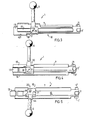
- a bolt mechanism 1 is displaceably mounted in a breech mechanism 2, the forward end of which is attached to a barrel 3.
- the breech mechanism 2 is intended to be provided on its underside with a triggering arrangement 4, which may be of conventional type, and therefore does not need to be described in detail in this connection.
- Fig. 1 the bolt mechanism is illustrated in its forward position with the bolt handle 5 pushed down in a transverse slot 6 in the breech mechanism 2.
- a guide sleeve 7 enclosed in the bolt mechanism 1 then reaches with its forward end up to the same position as the forward end of the cartridge opening 8 of the breech mechanism.
- the cartridge opening 8 is backwardly defined by an upper cross piece 9 on the breech mechanism 2.
- the guide sleeve 7 is provided along its sides with longitudinal guide ridges 14 and 15, moving in complemental grooves in the breech mechanism 2.
- a bolt mechanism 1, just removed from the breech mechanism 2, is illustrated in Fig. 3.
- the bolt 10 is guided in the guide sleeve 7 for the major part of its length.
- the cam profile 16 is formed such that on turning the bolt handle 5 from the position illustrated in Fig. 1 to that in Fig.
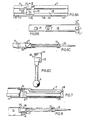
- the bolt 10 By moving the firing pin nut 13 backwards a sufficient length, from the position illustrated in Fig. 4 and against bias from the firing pin spring, the bolt 10 may be turned to the position illustrated in Fig. 5, in which the bolt mechanism 1 may be dismantled.
- the bolt 10 comprises a first part 19 and a second part 20, which are non- rotatably attached to each other in an assembled condition.
- the first part 19 is elongate and has a circular cross-section. At its forward end it carries the locking abutments 11 and at its rearward end it is provided with a radial projection 21 for engagement in a recess 22 (see Fig.
- the bolt mechanism 1 is illustrated in an entirely dismantled state in Fig. 6, where the different parts are illustrated with the same orientation as in Fig. 5.
- the guide sleeve 7 is provided with a circumferential locking groove 24, the width of which corresponds to the length of the sleeve 23.
- this locking groove 24 has an opening on the underside of the guide sleeve which is sufficiently large for the sleeve 23 to be inserted into the locking groove 24 from the underside of the guide sleeve 7.
- the locking groove 24 is forwardly defined by a support surface 26, the radial extension of which substantially corresponds to the material thickness of the sleeve 23 and the radial extension of the radial projection 21 on the first part 19.
- the first part 19 is locked axially forwards in relation to the guide sleeve 7 when the radial projection 21 is in contact with the support surface 26.
- a second radial support surface 27 restricts the locking groove 24 rearwards and is intended to co-act with the rear end of the sleeve 23 for locking the first part 19 axially backwards via the radial projection 21.
- the guide sleeve 7 has a bore 28 intended for the first part 19.
- first longitudinal recess 29 for the radial projection 21 of the first part 19.
- first recess 29 comprises a slot arranged on the underside of the guide sleeve 7, the width of the slot being less than the diameter of the bolt first part 19.
- second recess 30 in the guide sleeve 7 for the firing pin nut 13, the recess having the form of a longitudinal open slot towards the underside of the guide sleeve.
- this slot there is a support surface 31 facing towards the forward end of the guide sleeve.
- the first part 19 of the bolt is provided with an elongate hole 32 for the firing pin 33 and associated spring 34, illustrated in Fig. 6C.
- the firing pin 33 is rigidly connected to the firing pin nut 13 and carries a displaceably mounted support member 35 biassed by the firing pin spring 34, the member 35 thus being movable relative the nut 13. In an assembled state, this support member 35 is intended to be in contact with the support surface 31 in the guide sleeve 7.
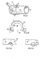
- FIG. 7 Further details in the embodiment of the guide sleeve 7 will be seen from Fig. 7.
- the implementation of the firing pin nut 13 and the support member 35 relatively movable thereto will be seen from Fig. 8.
- a cylindrical portion 36 on the support member 35 is intended to fit into the hole 32 in the bolt first part 19.
- the turning lock between the sleeve 23 and the first part 19 can of course be formed in a plurality of other ways than what has been illustrated here.
- the guide ridges 14 and 15 on the guide sleeve 7 are accommodated in corresponding grooves in the breech mechanism 2. Good guidance may be obtained merely with the aid of the guide ridges and the grooves, but it is also possible further to improve the guidance by allowing the walls of the guide sleeve to co-act with the walls of the breech mechanism. Furthermore, the locking abutments 11' and 11" on the bolt can to advantage have a shape and location such that they run in the same grooves as the guide ridges 14 and 15 when the bolt 10 is moved axially in the breech mechanism.
- the sleeve 23 included in the second part 20 of the bolt 10 can be precision-cast to advantage, machining of the cam profile 16 thus being eliminated. Since the first part 19 of the bolt also has a simple shape, manufacture of the bolt itself is considerably simplified, this otherwise being often complicated and expensive. By the simple locking determined by its form between the guide sleeve 7 and the part mounted in it, there are avoided complicated arrangements for mutual locking between the parts.
- the first recess 29 comprises a slot in the guide sleeve, but it is also quite possible to have a depression in connection with the bore 28 instead of a slot, and thus have a guide sleeve closed on the underside, at least at the first part 19 on the bolt 10.
- the bolt 10 By its mounting in the guide sleeve 7, the bolt 10 obtains very good guidance in the breech mechanism 2, both for axial and rotational movement. In turn this means that the bolt always has a well-defined firing position in the breech mechanism, which is important for shooting accuracy. This good guidance also enables smooth and comfortable handling of the bolt mechanism.
- the bolt second part 20 is first thrust over the firing pin 33 with the recess 22 facing toward the tip of the pin.
- the firing pin nut 13 is then placed in the second recess 30 in the guide sleeve 7, while the bolt second part 20 is placed in the locking groove 24, with the recess 22 oriented in extension to the first recess 29.
- the bolt first part 19 is then thrust into the bore 28 with the radial projection 21 accommodated in the first recess 29.
- the bolt is twisted in the guide sleeve 7 such that the different parts of the bolt mechanism assume the positions illustrated in Fig. 3.
- the bolt mechanism 1 can now be inserted in the breech mechanism 2.
- a longitudinal recess 38 in the guide ridge 14 on the guide sleeve 7 is defined by an abutment surface 39 at the forward end of the guide sleeve.
- the recess 38 is intended for abutment means (unillustrated) arranged in the breech mechanism 2 such as to arrest, in co-action with the abutment surface 39, the backward movement of the guide sleeve when the bolt mechanism has attained a fully withdrawn position.
- the bolt mechanism can be provided with different types of safety devices.
- a safety bolt intended for co-action with the firing pin nut 13 in the guide sleeve 7.
- Special advantages can, however, be achieved with a safety device 40 (Fig. 1) illustrated on the drawing, where a safety bolt 41 is rotatably mounted in the breech mechanism 2 for co-action with a recess 42 (Fig. 11) arranged in the firing pin nut 13.
- a safety bolt 41 is rotatably mounted in the breech mechanism 2 for co-action with a recess 42 (Fig. 11) arranged in the firing pin nut 13.
- the safety bolt 41 In the safety position, Fig. 11A, the safety bolt 41 is in engagement with the recess 42, thus latching against movement of the firing pin nut.
- Fig. 11A the safety bolt 41 is in engagement with the recess 42, thus latching against movement of the firing pin nut.
- a locking portion 43 in the form of a tip on the operating portion of the safety bolt41 is in engagement with a stop means 44, suitably a groove, on the handle 5 such that turning the handle upwards is prevented when the bolt mechanism is on safety.
- a stop means 44 suitably a groove
Landscapes
- Engineering & Computer Science (AREA)
- General Engineering & Computer Science (AREA)
- Aiming, Guidance, Guns With A Light Source, Armor, Camouflage, And Targets (AREA)
- Portable Nailing Machines And Staplers (AREA)
- Dowels (AREA)
- Spark Plugs (AREA)
Claims (11)
Priority Applications (1)
| Application Number | Priority Date | Filing Date | Title |
|---|---|---|---|
| AT85902696T ATE41510T1 (de) | 1984-05-04 | 1985-05-03 | Kammerverschluss fuer gewehre. |
Applications Claiming Priority (2)
| Application Number | Priority Date | Filing Date | Title |
|---|---|---|---|
| SE8402425A SE442549B (sv) | 1984-05-04 | 1984-05-04 | Geversmekanism av vridlastyp |
| SE8402425 | 1984-05-04 |
Publications (2)
| Publication Number | Publication Date |
|---|---|
| EP0179893A1 EP0179893A1 (de) | 1986-05-07 |
| EP0179893B1 true EP0179893B1 (de) | 1989-03-15 |
Family
ID=20355763
Family Applications (1)
| Application Number | Title | Priority Date | Filing Date |
|---|---|---|---|
| EP85902696A Expired EP0179893B1 (de) | 1984-05-04 | 1985-05-03 | Kammerverschluss für gewehre |
Country Status (6)
| Country | Link |
|---|---|
| US (1) | US4698931A (de) |
| EP (1) | EP0179893B1 (de) |
| DE (1) | DE3568862D1 (de) |
| FI (1) | FI860031A7 (de) |
| SE (1) | SE442549B (de) |
| WO (1) | WO1985005172A1 (de) |
Families Citing this family (22)
| Publication number | Priority date | Publication date | Assignee | Title |
|---|---|---|---|---|
| SE466119B (sv) * | 1990-01-17 | 1991-12-16 | Larsson Lars Gunnar | Gevaersmekanism |
| US5419070A (en) * | 1994-01-24 | 1995-05-30 | Rinehart; Theron N. | Rifle unloader apparatus |
| US5638626A (en) * | 1996-04-25 | 1997-06-17 | Westrom; Mark | Ammunition magazine |
| AT411295B (de) * | 1996-06-07 | 2003-11-25 | Steyr Daimler Puch Ag | Repetiergewehr mit halbstarr arretierbarem zylinderverschluss und schlagbolzensicherung |
| US5911173A (en) * | 1996-10-18 | 1999-06-08 | Westrom; Mark A. | Breech bolt assembly for a firearm |
| WO2007101292A1 (en) * | 2006-03-09 | 2007-09-13 | Lowe, Deborah, Gale | Bolt protector |
| US9151553B2 (en) * | 2007-01-10 | 2015-10-06 | Smith & Wesson Corp. | Bolt action firearm and its method of assembly |
| CA2709047C (en) * | 2010-07-06 | 2011-12-13 | Joseph Szecsei | Improvements in double barrel bolt action rifle |
| US8925230B2 (en) * | 2011-12-15 | 2015-01-06 | Sturm, Ruger & Company, Inc. | Bolt handle assembly for firearm |
| US9097478B1 (en) | 2012-02-17 | 2015-08-04 | Theodore Karagias | Bolt mechanisms and firearms containing the same |
| US9115941B2 (en) | 2013-03-15 | 2015-08-25 | Saeilo Enterprises, Inc. | Straight pull bolt action system |
| US9377255B2 (en) | 2014-02-03 | 2016-06-28 | Theodore Karagias | Multi-caliber firearms, bolt mechanisms, bolt lugs, and methods of using the same |
| DE202015106525U1 (de) * | 2015-12-01 | 2017-03-06 | L&O Hunting Group GmbH | Gewehr mit einem Schlagmechanismus |
| US10514219B2 (en) * | 2017-09-11 | 2019-12-24 | Q, Llc | Removable bolt handle for bolt action firearms |
| USD868196S1 (en) | 2017-09-11 | 2019-11-26 | Q, Llc | Firearm bolt handle |
| USD854643S1 (en) | 2017-11-07 | 2019-07-23 | Q, Llc | Firearm bolt handle |
| RU2701891C1 (ru) * | 2018-11-08 | 2019-10-02 | Общество С Ограниченной Ответственностью "Промтехнология" | Запирающий механизм стрелкового оружия |
| US11067347B2 (en) | 2018-11-30 | 2021-07-20 | Theodore Karagias | Firearm bolt assembly with a pivoting handle |
| US12215947B2 (en) | 2018-11-30 | 2025-02-04 | Theodore Karagias | Firearm bolt assembly with a pivoting handle |
| US11137224B2 (en) * | 2019-08-21 | 2021-10-05 | Ardesa, S.A. | Rifles and muzzle loading rifles receiving propellant charges in break open and bolt action configurations, and barrel extensions therefor |
| US11946714B2 (en) * | 2021-06-02 | 2024-04-02 | Springfield, Inc. | Bolt assembly with clip |
| US12181235B2 (en) * | 2022-05-24 | 2024-12-31 | Gunwerks Llc | Barrel extension extraction cam and barrel extension system |
Family Cites Families (11)
| Publication number | Priority date | Publication date | Assignee | Title |
|---|---|---|---|---|
| GB190100519A (en) * | 1901-01-08 | 1901-11-30 | Charles Henry Augustus Fr Ross | Improvements in Small Arms and Machine Guns. |
| SE41093C1 (de) * | 1914-05-06 | 1916-08-02 | ||
| CH91355A (de) * | 1920-12-03 | 1921-11-01 | Waffenfabrik Mauser Aktiengese | Zylinderverschluss. |
| US3387400A (en) * | 1967-05-08 | 1968-06-11 | Olin Mathieson | Automatic safety device with manual release for bolt action firearms |
| DE1932036C3 (de) * | 1968-06-29 | 1974-03-21 | Howa Kogyo K.K., Nagoya, Aichi (Japan) | Zylinder-Drehkammerverschluß für als Einzellader ausgebildete Gewehre |
| US3710492A (en) * | 1970-12-02 | 1973-01-16 | Emhart Corp | Travel guide for bolt action rifles |
| DE2212934A1 (de) * | 1972-03-17 | 1973-09-20 | Philips Nv | Verfahren zur herstellung eines im wesentlichen aus eisen bestehenden metallpulvers |
| SE393183B (sv) * | 1974-08-13 | 1977-05-02 | L A V Andersson | Slutstycke for handeldvapen |
| US4305218A (en) * | 1980-03-03 | 1981-12-15 | Godsey Floyd E | Safety mechanism for a firearm |
| DE3128369A1 (de) * | 1981-02-13 | 1983-02-03 | Tedeco AG, 6330 Cham | "schlossvorrichtung" |
| AU7934982A (en) * | 1981-12-11 | 1983-06-30 | Nilsson, C. O. L. | Vapensystem med cylindermekanism |
-
1984
- 1984-05-04 SE SE8402425A patent/SE442549B/sv not_active IP Right Cessation
-
1985
- 1985-05-03 FI FI860031A patent/FI860031A7/fi not_active Application Discontinuation
- 1985-05-03 US US06/833,384 patent/US4698931A/en not_active Expired - Fee Related
- 1985-05-03 WO PCT/SE1985/000196 patent/WO1985005172A1/en not_active Ceased
- 1985-05-03 EP EP85902696A patent/EP0179893B1/de not_active Expired
- 1985-05-03 DE DE8585902696T patent/DE3568862D1/de not_active Expired
Also Published As
| Publication number | Publication date |
|---|---|
| SE8402425L (sv) | 1985-11-05 |
| EP0179893A1 (de) | 1986-05-07 |
| DE3568862D1 (en) | 1989-04-20 |
| FI860031A0 (fi) | 1986-01-03 |
| US4698931A (en) | 1987-10-13 |
| SE8402425D0 (sv) | 1984-05-04 |
| FI860031L (fi) | 1986-01-03 |
| SE442549B (sv) | 1986-01-13 |
| WO1985005172A1 (en) | 1985-11-21 |
| FI860031A7 (fi) | 1986-01-03 |
Similar Documents
| Publication | Publication Date | Title |
|---|---|---|
| US4698931A (en) | Rifle bolt mechanism and safety | |
| US4398366A (en) | Gun lock | |
| US5722194A (en) | Weapon bolt | |
| CA2962313C (en) | Receiver with an ambidextrous bolt stop | |
| US5906066A (en) | Automatic pistol mechanism | |
| US3675534A (en) | Automatic rifle | |
| FI79191B (fi) | Laosanordning foersedd med ett vridbart laoshuvud och ett roerligt laoselement foer automatiska eldvapen. | |
| EP1210559B1 (de) | Verriegelungsvorrichtung für feuerwaffen | |
| US20050188578A1 (en) | Firearm | |
| US2345127A (en) | Gun having sliding and interchangeable barrel | |
| GB2090649A (en) | Automatic or semi-automatic gun | |
| US4015357A (en) | Firearm bolt | |
| EP0044632B1 (de) | Bedienungsmechanismus für Handfeuerwaffen | |
| US6481137B2 (en) | Revolving firearm | |
| US4308786A (en) | Trigger device for automatic gun | |
| US2971441A (en) | Fire rate control means for a telescopic-type two-piece firearm bolt | |
| US4821621A (en) | Multipurpose repeating firearm having alternate firing mechanisms | |
| KR890000195B1 (ko) | 자동 소형화기(hand firearm) | |
| US7353631B2 (en) | Muzzle-loading firearm | |
| KR102777635B1 (ko) | 브리치블록 및 브리치블록을 갖는 무기 시스템 | |
| US7059074B1 (en) | Muzzle-loading firearm | |
| US1172069A (en) | Short straight-pull breech-action for military hand-firearms. | |
| FI59744B (fi) | Pulverkraftsdriven indrivningsanordning eller bultpistol | |
| US4860632A (en) | Apparatus for radially securing a cartridge inserted by a breechblock into the weapon barrel of a firing weapon | |
| GB2024383A (en) | Extractor mechanism |
Legal Events
| Date | Code | Title | Description |
|---|---|---|---|
| PUAI | Public reference made under article 153(3) epc to a published international application that has entered the european phase |
Free format text: ORIGINAL CODE: 0009012 |
|
| AK | Designated contracting states |
Kind code of ref document: A1 Designated state(s): AT BE CH DE FR GB IT LI LU NL |
|
| 17P | Request for examination filed |
Effective date: 19860522 |
|
| 17Q | First examination report despatched |
Effective date: 19871001 |
|
| GRAA | (expected) grant |
Free format text: ORIGINAL CODE: 0009210 |
|
| AK | Designated contracting states |
Kind code of ref document: B1 Designated state(s): AT BE CH DE FR GB IT LI LU NL |
|
| REF | Corresponds to: |
Ref document number: 41510 Country of ref document: AT Date of ref document: 19890415 Kind code of ref document: T |
|
| REF | Corresponds to: |
Ref document number: 3568862 Country of ref document: DE Date of ref document: 19890420 |
|
| ITF | It: translation for a ep patent filed | ||
| PG25 | Lapsed in a contracting state [announced via postgrant information from national office to epo] |
Ref country code: LU Free format text: LAPSE BECAUSE OF NON-PAYMENT OF DUE FEES Effective date: 19890531 |
|
| ET | Fr: translation filed | ||
| PLBE | No opposition filed within time limit |
Free format text: ORIGINAL CODE: 0009261 |
|
| STAA | Information on the status of an ep patent application or granted ep patent |
Free format text: STATUS: NO OPPOSITION FILED WITHIN TIME LIMIT |
|
| 26N | No opposition filed | ||
| PGFP | Annual fee paid to national office [announced via postgrant information from national office to epo] |
Ref country code: GB Payment date: 19900427 Year of fee payment: 6 |
|
| PGFP | Annual fee paid to national office [announced via postgrant information from national office to epo] |
Ref country code: LU Payment date: 19900504 Year of fee payment: 6 |
|
| PGFP | Annual fee paid to national office [announced via postgrant information from national office to epo] |
Ref country code: BE Payment date: 19900517 Year of fee payment: 6 |
|
| PGFP | Annual fee paid to national office [announced via postgrant information from national office to epo] |
Ref country code: DE Payment date: 19900522 Year of fee payment: 6 |
|
| PGFP | Annual fee paid to national office [announced via postgrant information from national office to epo] |
Ref country code: AT Payment date: 19900523 Year of fee payment: 6 |
|
| PGFP | Annual fee paid to national office [announced via postgrant information from national office to epo] |
Ref country code: CH Payment date: 19900525 Year of fee payment: 6 |
|
| PGFP | Annual fee paid to national office [announced via postgrant information from national office to epo] |
Ref country code: FR Payment date: 19900530 Year of fee payment: 6 |
|
| ITTA | It: last paid annual fee | ||
| PGFP | Annual fee paid to national office [announced via postgrant information from national office to epo] |
Ref country code: NL Payment date: 19900531 Year of fee payment: 6 |
|
| PG25 | Lapsed in a contracting state [announced via postgrant information from national office to epo] |
Ref country code: GB Effective date: 19910503 Ref country code: AT Effective date: 19910503 |
|
| PG25 | Lapsed in a contracting state [announced via postgrant information from national office to epo] |
Ref country code: LI Effective date: 19910531 Ref country code: CH Effective date: 19910531 Ref country code: BE Effective date: 19910531 |
|
| BERE | Be: lapsed |
Owner name: LANO VAPEN OCH FINMEKANIK Effective date: 19910531 |
|
| PG25 | Lapsed in a contracting state [announced via postgrant information from national office to epo] |
Ref country code: NL Effective date: 19911201 |
|
| GBPC | Gb: european patent ceased through non-payment of renewal fee | ||
| NLV4 | Nl: lapsed or anulled due to non-payment of the annual fee | ||
| PG25 | Lapsed in a contracting state [announced via postgrant information from national office to epo] |
Ref country code: FR Effective date: 19920131 |
|
| REG | Reference to a national code |
Ref country code: CH Ref legal event code: PL |
|
| PG25 | Lapsed in a contracting state [announced via postgrant information from national office to epo] |
Ref country code: DE Effective date: 19920303 |
|
| REG | Reference to a national code |
Ref country code: FR Ref legal event code: ST |