EP0179997A1 - Machine pour emballer des petits produit, comme des têtes de laitue, des bottes de carottes, des asperges, des bananes, etc. - Google Patents
Machine pour emballer des petits produit, comme des têtes de laitue, des bottes de carottes, des asperges, des bananes, etc. Download PDFInfo
- Publication number
- EP0179997A1 EP0179997A1 EP85110267A EP85110267A EP0179997A1 EP 0179997 A1 EP0179997 A1 EP 0179997A1 EP 85110267 A EP85110267 A EP 85110267A EP 85110267 A EP85110267 A EP 85110267A EP 0179997 A1 EP0179997 A1 EP 0179997A1
- Authority
- EP
- European Patent Office
- Prior art keywords
- film web
- film
- rotating ring
- storage trays
- holding tubes
- Prior art date
- Legal status (The legal status is an assumption and is not a legal conclusion. Google has not performed a legal analysis and makes no representation as to the accuracy of the status listed.)
- Granted
Links
Images


Classifications
-
- B—PERFORMING OPERATIONS; TRANSPORTING
- B65—CONVEYING; PACKING; STORING; HANDLING THIN OR FILAMENTARY MATERIAL
- B65B—MACHINES, APPARATUS OR DEVICES FOR, OR METHODS OF, PACKAGING ARTICLES OR MATERIALS; UNPACKING
- B65B11/00—Wrapping, e.g. partially or wholly enclosing, articles or quantities of material, in strips, sheets or blanks, of flexible material
- B65B11/02—Wrapping articles or quantities of material, without changing their position during the wrapping operation, e.g. in moulds with hinged folders
- B65B11/025—Wrapping articles or quantities of material, without changing their position during the wrapping operation, e.g. in moulds with hinged folders by webs revolving around stationary articles
-
- B—PERFORMING OPERATIONS; TRANSPORTING
- B65—CONVEYING; PACKING; STORING; HANDLING THIN OR FILAMENTARY MATERIAL
- B65B—MACHINES, APPARATUS OR DEVICES FOR, OR METHODS OF, PACKAGING ARTICLES OR MATERIALS; UNPACKING
- B65B25/00—Packaging other articles presenting special problems
- B65B25/02—Packaging agricultural or horticultural products
- B65B25/04—Packaging fruit or vegetables
-
- B—PERFORMING OPERATIONS; TRANSPORTING
- B65—CONVEYING; PACKING; STORING; HANDLING THIN OR FILAMENTARY MATERIAL
- B65B—MACHINES, APPARATUS OR DEVICES FOR, OR METHODS OF, PACKAGING ARTICLES OR MATERIALS; UNPACKING
- B65B2210/00—Specific aspects of the packaging machine
- B65B2210/14—Details of wrapping machines with web dispensers for application of a continuous web in layers onto the articles
- B65B2210/18—Details of wrapping machines with web dispensers for application of a continuous web in layers onto the articles the web dispenser being mounted on a rotary ring
Definitions
- the invention relates to a device for packaging small items, such as lettuce heads, carrots, asparagus, bananas and the like, folded into a bunch, by wrapping the small items with a plastic film band, in particular stretch film.
- the partial wrapping is known by means of a banderole which does not completely enclose the packaged item but leaves two sides opposite one another open.
- the design effort of the known devices for wrapping packaged goods with banderoles is very complex because, on the one hand, guiding the film web around the packaged goods must be ensured and, on the other hand, it is necessary that after the end of a packaging process the end of the film web is brought into a position within easy reach and is held in this so that the end of the film web can be grasped for the subsequent packaging process and placed around the goods to be packed.
- the invention solves the problem of creating an economically working device for inexpensive packaging of small items with a foil band, with which heads of lettuce and fruits bundled together, such as bananas, carrots, asparagus and the like. can be packaged in order to be able to carry out price labeling on the banderole, and in which the respective film web end is kept ready so that without additional technical facilities wrapping processes are feasible.
- a generic packaging device which is designed according to the invention in such a way that in a support frame two in the longitudinal direction one behind the other and with a gap at a distance from each other, the packaging material with its end regions receiving storage trays, one by one parallel to Storage axis longitudinal axis of rotation by means of a drive device rotatable by at least a full and a half turn, rotating around one of the two storage trays in its end region facing the intermediate space, which is guided between bearing and guide rollers and which has a laterally projecting, rod-like, parallel to the rotating axis Bracket with a film web supply drum running around the intermediate space between the two storage trays, together with the rotating ring, two in the longitudinal direction one behind the other and below the storage trays and in the interior of the rotating ring, via flexible hose lines connected to a vacuum generating device with a switch-on and switch-off valve, foil web end tubes, the opposite ends of which, below the foil web supply drum, are provided with air intake openings
- a device designed in accordance with the invention it is possible to pack small items economically with a film sleeve.
- heads of lettuce and carrots, asparagus, bananas and the like folded into a bunch can also be used with the device.
- be provided with a film banderole which can be provided with price information, the film web used for this purpose being able to be provided with corresponding price information during the manufacture of the packaging; however, it is also possible to subsequently print and apply price information to the created film sleeve.
- the device works with a high degree of economy, since it has a simple construction and only a little film is required for the packaging process, so that ultimately inexpensive packaging is obtained.
- the simplest technical means are used to hold or grasp the end of the film web in order to be able to place the film web around the goods to be packaged by pulling them off a film storage drum, with the end of the film web being separated from the actual film web from being separated from the actual film web for carrying out a new packaging process is kept in a handy position.
- An additional pressing of the end of the film web section wrapped around the packaged goods after its separation from the actual one Film web is not necessary since the end of the film web section automatically contacts the film wrapping of the goods to be packaged, while at the same time the free end of the film web is held by vacuum on two film web end holder tubes.
- the release of the free end of the film web after the packaging material has been wrapped from the film web end holder tubes is carried out by moving the holding tubes apart while simultaneously rotating the holding tubes about their longitudinal axes. Only through this sequence of movements is it possible to detach the film web from the holding tubes under vacuum without the film web slipping, folding or the like.
- the packaging of lettuce heads with the foil banding using the device is particularly advantageous, since in this way a lettuce head packaging is created which makes it possible to avoid the disadvantages that would otherwise arise when selling lettuce heads, which consist in the fact that lettuce heads offered for sale only can be kept fresh over a longer period of time with complex aids.
- the foil bands used are free from rot and enable the storage and storage of such packed heads of lettuce in water-containing containers or tubs.
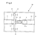
- the device designated 100 and shown in FIG. 1 for packaging small items such as lettuce heads, carrots, asparagus, bananas and the like folded into a bunch consists of a support frame 10 which can be provided with uprights 13, 14 which carry rollers 15, 16 at their bottom ends 13a, 14a in order to be able to move the packaging device 100 to another place of use.
- two storage trays 11, 111 are arranged one behind the other in the longitudinal direction, an intermediate space 12 being formed between the ends 11a, 11la of the storage trays 11, 111 facing each other.
- the storage trays 11, 111 are slidably held in guides 10 not shown in the drawing, the storage trays 11, 111 in their respective positions with locking devices, such as clamping or locking devices, which are designed in a manner known per se are lockable.
- Both storage trays 11, 111 are designed as half-trays and in such a way that the packaging material can be inserted into the storage trays 11, 111 in such a way that the packaging material V comes to rest with its end regions in the storage trays 11, 111, while the central region of the packaging material V in the space 12 between the two storage trays 11,111.
- the displaceability of the two storage trays 11, 111 to change the size of the intermediate space 12 is indicated in FIG. 1 by the arrows X, XI.
- a vertical rotating ring 20 Arranged in the support frame 10 is a vertical rotating ring 20 which is guided and held in outer and inner bearing and guide rollers 23, 24 (FIG. 3). These bearing and guide rollers 23, 24 are held on the support frame 10.
- the arrangement of the rotating ring 20. in the support frame 10 is such that its axis of rotation arranged at 25 is parallel to the longitudinal axis of the storage trays 11, 111. Furthermore, the rotating ring 20 runs around one of the two storage trays 11, 111. In the embodiment shown in Fig. 1, the rotating ring 20 is arranged to the tray 11 such that the front portion 11a of the tray 11 comes to rest in the interior of the rotating ring 20, i.e.
- the rotating ring 20 runs around the end region 11a of the storage tray 11 and is thus laterally offset from the intermediate space 12 in the support frame 10.
- the storage tray 11 and the storage tray 111 are thus in the region of the axis of rotation 25 of the rotary ring 20.
- the rotating ring 20 can be rotated about its axis of rotation 25 in the direction of arrow Y by means of a drive device 21 (FIG. 3).
- An electromotive drive can be used as the drive device 21; however, other drive devices can also be used.
- a drive wheel 22 arranged on the shaft of the drive device is operatively connected to the rotary ring 20 in order to be able to set it in rotation.
- the rotating ring 20 carries a laterally cantilevered, rod-like holder 26, which runs parallel to its axis of rotation 25, in the form of a bearing axis for a storage drum 27 for a film web FB.
- This film web supply drum 27 is provided with a trigger brake, e.g. a friction brake, in order to avoid, in the case of a film pull-off in the direction of arrow Z, that because of the freewheeling of the storage drum, more film web is dispensed in length than is required.
- a trigger brake e.g. a friction brake
- the film supply on the drum 27 consists of a sheet of plastic film, in particular of stretch film.
- the overall arrangement of the film web supply drum 27 in connection with the rotating ring 20 is such that the film web FB can be passed between the two storage trays 11, 111.
- the width of the film web FB is dimensioned somewhat smaller than the width of the intermediate space 12 between the two storage trays 11, 111; the width of the film web will depend on the length of the packaged goods and the desired packaging width. Characterized in that the two storage trays 11, 111 are displaceable in the support frame 10 to change the space 12, it is possible to use wider or narrower film webs, so that the cheapest film web width can be used in each case in adaptation to the packaging material.
- two holding tubes 30, 130 are arranged in the support frame 10, which serve to hold the film web end FB1.
- These holding tubes 30, 130 are arranged one behind the other corresponding to the storage trays 11, 111, so that their central longitudinal axes are aligned with one another.
- the arrangement of these holding tubes 30, 130 is such that their mutually facing ends 30a, 130a come to lie below the intermediate space 12 between the two storage trays 11, 111, as can be seen from FIG. 1.
- Each of the two holding tubes 30, 130 has a number of air intake openings 34, 134 at its ends 30a and 130a, distributed over its circumference. Furthermore, each holding tube 30 or 130 is connected via a flexible hose line 31, 131 to a vacuum generating device 32 which is arranged in the support frame 10 and which is provided with an on and off valve 33.
- the two holding tubes 30, 130 are held laterally movable in the support frame 10, so that the free holding tube ends 30a, 130a with their air intake openings 34, 134 can be led out of the area of the film web FB.
- working cylinders 37, 137 are provided in the support frame 10, which e.g. can be operated hydraulically or with compressed air; however, other suitable drive devices can also be used here.
- the piston rods 38, 138 of the two working cylinders 37, 137 are connected to the ends of the holding tubes 30, 130 facing away from the holding tube ends 30a, 130a carrying the air intake openings 34, 134 so that, when the working cylinders 37, 137 are actuated accordingly, the piston rods 38, 138 with their holding tubes 30, 130 can be moved in the direction of the arrows X2, X3 are (Fig.l) and that the holding tubes can twist about their longitudinal axes.
- the holding tubes 30, 130 are designed in such a way that the holding tubes 30, 130 simultaneously rotate about their longitudinal axes in the direction of the arrows X4, X5 when they are moved apart.
- This rotation of the holding tubes 30, 130 about their longitudinal axes takes place through a spindle-like configuration of the two holding tubes 30, 130.
- both holding tubes 30, 130 are as spindles 36, 136, i.e. with thread-like guides, and are also guided in fixed guides 35, 135 such that when the holding pipes 30, 130 move apart, the holding pipes 30, 130 rotate about their longitudinal axes.
- a separating knife 30 or another suitable film separating device is provided in the supporting frame (FIG. 3).
- the separating knife 40 is connected to a drive device 41 via which the separating knife 40 can be inserted into the respective required separating area in order to be able to separate the film band from the actual film web FB after the band around the packaging material has been applied.
- All drive devices of the packaging device 100 are brought together in a control device 50, with which the individual required process sequences are controlled.
- the drive device 21 for the rotary ring 20 are included the film supply roll 27, the working cylinders 37, 137 for the holding tubes 30, 130, the on and off valve 33 for the vacuum generating device 32 and the drive device 41 for the separating knife 40 are brought together (FIG. 1).
- the packaging device 100 works as follows:
- the vacuum generating device 32 After placing the film web supply drum 27 on the bearing shaft 26 on the rotating ring 20, the vacuum generating device 32 is put into operation, so that air is sucked in through the openings 34, 134 at the ends 30a, 130a of the holding tubes 30, 130.
- the two holding tubes 30, 130 In the starting position, the two holding tubes 30, 130 have the position shown in FIG. 1 below the space 12 between the two storage trays 11, 111.
- the goods V to be packaged are placed in the storage trays 11, 111 in such a way that the end regions of the packaging goods V come to rest in the storage trays 11, 111.
- the central free area of the packaging material V then lies in the intermediate space 12.
- the film web is pulled by hand in the direction of arrow Z from the film supply drum 27 until the film web end FB1 comes to rest in the region of the ends 30a, 130a of the holding tubes 30, 130, the film web end FB1 encompassing a portion of the holding pipe ends 30a, 130a (FIG. 3 ). Because the holding tubes 30, 130 are connected to the vacuum generating device 32, the foil web end FB1 is held on the holding tubes 30, 130 via the air intake openings 34, 134 on the holding tube ends 30a, 130a, starting from the position of the rotating ring 20 with the foil web supply drum shown in A in FIG. 3 27 is connected to the drive device via the control device 50 21 for the rotating ring 20 this is rotated in the direction of arrow Y.
- the film web supply drum 27 takes part in this rotation of the rotating ring 20 and is first moved into the starting position A via the positions B, C and D, the film web FB being placed around the packaged goods V and around the ends 30a, 130a of the holding tubes 30, 130. Since the two holding tubes 30, 130 have the closed position shown in FIG. 1, when the film web storage drum 27 rotates, the film web is not only placed around the packaged goods V, but also in the lower region around the ends 30a, 130a of the holding tubes 30, 130, for example if Rotary ring 20 with its film web drum 27 has reached position D in Figure 3.
- the two working cylinders 37, 137 are switched on, with the result that the two holding tubes 30, 130 are moved apart, with simultaneous rotation of the holding tubes 30, 130 in the direction of arrow Z, so that when Moving apart the holding tubes 30, 130 and the rotary movements carried out at the same time about the longitudinal axes of the holding tubes 30, 130, the film web end FB1 from the ends 30a, 130a of the holding tubes 30, 130 is released, which is possible due to these rotary movements, since the vacuum generating device 32 is switched on during the entire process and air is drawn in through the openings 34, 134 in the ends 30a, 130a of the holding tubes 30, 130.
- the direction of rotation of the holding tubes 30, 130 is preferably in opposite directions when moving apart.
- the rotary ring 20 is simultaneously moved in the direction of the arrow Y, with the result that its film web supply drum 27 is also moved, which is what leads to the fact that the film web is applied to the packaged goods V or is used for the packaged goods, since the path through the opened holding tubes 30, 130 is released for this approach of the film web to the packaged goods.
- the two holding tubes 30, 130 are moved towards one another again by the working cylinders 37, 137 in the closed position shown in FIG. 1, the vacuum generating device 32 being and shut-off valve 33 can be temporarily put out of operation, since the holding tubes 30, 130 do not have to hold an end of the film web first.
- the film web supply drum 27 then runs again around the packaged goods V when the rotary ring 20 continues to rotate until position D is reached again approximately.
- the two holding tubes 30, 130 again have the closed position shown in FIG. 1, ie moved towards one another, during this cycle up to position D, the film web runs over a section of the Outer circumference of the two holding tube ends 30a, 130a.
- the vacuum generating device 32 is put into operation again, so that the film web in the contact area is drawn onto the holding tube ends 30a, 130a and held by the ends.
- the separating knife 40 is moved by means of the drive device 41 into the film web area in the direction of the arrow Z1 and separates the film web from the film web section enveloping the packaging material V.
- the free end FB1 of the film web FB is held by the ends 30a, 130a of the holding tubes 30, 130, while the free end of that film web section which has been exposed by cutting off the film web FB is placed against the film web section which already surrounds the packaged goods V. .
- This positioning of the free end of the film web section, which is placed around the packaging material V takes place automatically, specifically because of the adhesive forces which exist between this film web end and the film web section wrapped around the packaging material V.
- the packaging material V is thus wrapped like a band, i.e. packed, and is removed from the two storage trays 11, 111, while the rotary ring 20 is interrupted in its rotational movement. New goods to be packaged are placed in the storage trays 11, 111 in the same way.
- the packaging process, as described above, can begin again since the free end FB1 of the film web FB is held by the holding tubes 30, 130.
Landscapes
- Engineering & Computer Science (AREA)
- Mechanical Engineering (AREA)
- Life Sciences & Earth Sciences (AREA)
- Agronomy & Crop Science (AREA)
- Packaging Of Special Articles (AREA)
- Basic Packing Technique (AREA)
- Preparation Of Fruits And Vegetables (AREA)
Priority Applications (1)
| Application Number | Priority Date | Filing Date | Title |
|---|---|---|---|
| AT85110267T ATE33808T1 (de) | 1984-08-30 | 1985-08-16 | Vorrichtung zum verpacken von kleinstueckguetern, wie salatkoepfe, zu einem bund zusammengelegte mohrrueben, spargel, bananen u. dgl. |
Applications Claiming Priority (2)
| Application Number | Priority Date | Filing Date | Title |
|---|---|---|---|
| DE8425616 | 1984-08-30 | ||
| DE8425616U | 1984-08-30 |
Publications (2)
| Publication Number | Publication Date |
|---|---|
| EP0179997A1 true EP0179997A1 (fr) | 1986-05-07 |
| EP0179997B1 EP0179997B1 (fr) | 1988-04-27 |
Family
ID=6770252
Family Applications (1)
| Application Number | Title | Priority Date | Filing Date |
|---|---|---|---|
| EP85110267A Expired EP0179997B1 (fr) | 1984-08-30 | 1985-08-16 | Machine pour emballer des petits produit, comme des têtes de laitue, des bottes de carottes, des asperges, des bananes, etc. |
Country Status (4)
| Country | Link |
|---|---|
| US (1) | US4628671A (fr) |
| EP (1) | EP0179997B1 (fr) |
| AT (1) | ATE33808T1 (fr) |
| DE (1) | DE3562355D1 (fr) |
Cited By (1)
| Publication number | Priority date | Publication date | Assignee | Title |
|---|---|---|---|---|
| EP0388561A3 (fr) * | 1988-12-30 | 1990-10-24 | BEMIS COMPANY, Inc. | Dispositif d'empaquetage avec un film étirable |
Families Citing this family (13)
| Publication number | Priority date | Publication date | Assignee | Title |
|---|---|---|---|---|
| FI82010C (fi) * | 1988-11-30 | 1991-01-10 | Pesmel Insinoeoeritoimisto | Anordningskombination i en foerpackningsmaskin. |
| US5070676A (en) * | 1988-12-30 | 1991-12-10 | Bemis Company, Inc. | Stretch bundling |
| US4939989A (en) * | 1989-03-02 | 1990-07-10 | Donald Zacharias | Tree limb folding and tying apparatus |
| US4979358A (en) * | 1989-05-31 | 1990-12-25 | Keip Charles P | Rotary film wrapping apparatus |
| US5027579A (en) * | 1989-05-31 | 1991-07-02 | Keip Machine Company | Wrapping apparatus |
| US5027581A (en) * | 1990-05-30 | 1991-07-02 | Hayssen Manufacturing Company | Wrapping method and apparatus |
| US5404691A (en) * | 1993-06-23 | 1995-04-11 | Mima Incorporated | Film-severing mechanism for wrapping machine and related method |
| US5564258A (en) * | 1994-11-10 | 1996-10-15 | Lanatech, Inc. | Method and apparatus for holding and wrapping stretch wrap packaging material |
| US6666133B2 (en) | 2001-04-11 | 2003-12-23 | Lee W. Squyres | Standing tree baler |
| AU2003902756A0 (en) * | 2003-06-03 | 2003-06-19 | Envirotrend Pty Ltd | A Method of, and a Binding for, Packaging Bananas |
| AU2005222735B2 (en) * | 2004-03-23 | 2010-05-20 | Ibs Engineering Supplies Pty Ltd | Apparatus for wrapping adhesive tape around articles |
| WO2005090164A1 (fr) * | 2004-03-23 | 2005-09-29 | Robert & Karen Borsato Pty Limited | Appareil servant a enrouler du ruban adhesif autour d'articles |
| TW201127699A (en) * | 2010-02-12 | 2011-08-16 | Adv Flexible Circuits Co Ltd | Wire winding apparatus |
Citations (2)
| Publication number | Priority date | Publication date | Assignee | Title |
|---|---|---|---|---|
| US4079565A (en) * | 1974-03-25 | 1978-03-21 | Lantech Inc. | Stretch-wrapped package, process and apparatus |
| DE3136435A1 (de) * | 1981-09-14 | 1983-03-31 | B. Hagemann & Co, 4430 Steinfurt | "raff- und schneidvorrichtung fuer verpackungsmaschinen" |
Family Cites Families (5)
| Publication number | Priority date | Publication date | Assignee | Title |
|---|---|---|---|---|
| US2624990A (en) * | 1948-09-09 | 1953-01-13 | Savannah Sugar Refining Corp | Bag wrapping machine |
| US2945336A (en) * | 1957-04-04 | 1960-07-19 | Minnesota Mining & Mfg | Circumferential tape applying |
| DE2164038A1 (de) * | 1971-12-23 | 1973-07-05 | Hans Boehl Maschinenfabrik | Einwickelmaschine |
| US4461136A (en) * | 1981-12-30 | 1984-07-24 | Quachita Machine Works, Inc. | Method and apparatus for enveloping a plurality of items in a stretchable film |
| DE3236438C2 (de) * | 1982-10-01 | 1986-02-06 | Union Sils, van de Loo & Co GmbH, 5758 Fröndenberg | Vorrichtung zum Umwickeln von Drahtspeichenbunden mit Bandmaterial aus Stretchfolie |
-
1985
- 1985-08-16 DE DE8585110267T patent/DE3562355D1/de not_active Expired
- 1985-08-16 EP EP85110267A patent/EP0179997B1/fr not_active Expired
- 1985-08-16 AT AT85110267T patent/ATE33808T1/de not_active IP Right Cessation
- 1985-08-20 US US06/767,474 patent/US4628671A/en not_active Expired - Fee Related
Patent Citations (2)
| Publication number | Priority date | Publication date | Assignee | Title |
|---|---|---|---|---|
| US4079565A (en) * | 1974-03-25 | 1978-03-21 | Lantech Inc. | Stretch-wrapped package, process and apparatus |
| DE3136435A1 (de) * | 1981-09-14 | 1983-03-31 | B. Hagemann & Co, 4430 Steinfurt | "raff- und schneidvorrichtung fuer verpackungsmaschinen" |
Cited By (1)
| Publication number | Priority date | Publication date | Assignee | Title |
|---|---|---|---|---|
| EP0388561A3 (fr) * | 1988-12-30 | 1990-10-24 | BEMIS COMPANY, Inc. | Dispositif d'empaquetage avec un film étirable |
Also Published As
| Publication number | Publication date |
|---|---|
| ATE33808T1 (de) | 1988-05-15 |
| EP0179997B1 (fr) | 1988-04-27 |
| DE3562355D1 (en) | 1988-06-01 |
| US4628671A (en) | 1986-12-16 |
Similar Documents
| Publication | Publication Date | Title |
|---|---|---|
| DE69014297T2 (de) | Verfahren und vorrichtung zum verpacken. | |
| DE68902074T2 (de) | Vorrichtung und verfahren zum ausbreiten der deckfolie einer verpackung. | |
| DE2262291A1 (de) | Vorrichtung zum aufwickeln und verpacken eines schlauchartigen gebildes | |
| CH685121A5 (de) | Verfahren und Vorrichtung zum Entfernen der Verpackung (Emballage) von textilen Rohstoffballen. | |
| EP0179997B1 (fr) | Machine pour emballer des petits produit, comme des têtes de laitue, des bottes de carottes, des asperges, des bananes, etc. | |
| EP0120251A1 (fr) | Procédé et dispositif d'enveloppement d'objets de préférence quadrangulaires avec un matériau d'emballage sous forme de bande | |
| DE2847556A1 (de) | Revolverkopf-aufwickelmaschine fuer bandfoermiges material | |
| DE1278327B (de) | Vorrichtung zum Stapeln und Einwickeln von Muenzen, Spielmarken od. dgl. in eine Folie | |
| DE69105359T2 (de) | Vorrichtung zum Zuführen von Bindedraht. | |
| EP0243906B1 (fr) | Procédé et dispositif pour faire des paquets tubulaires portatifs d'imprimés comme des journaux, des revues et similaires | |
| DE3125689C2 (fr) | ||
| DE2317186A1 (de) | Verfahren zum verpacken flexibler kunststoffbeutel | |
| DE3328915A1 (de) | Vorrichtung zum entwickeln von bonbons oder aehnlichen gegenstaenden bei kontinuierlicher bewegung in sogenannte wickelhuellen mit zwei gedrehten enden | |
| DE4015643A1 (de) | Verfahren und vorrichtung zum verpacken von pressballen | |
| DE3913249A1 (de) | Verfahren zum wechseln eines baumes in einer schaer- bzw. zettelvorrichtung und schaer- bzw. zettelvorrichtung | |
| DE3621651C2 (de) | Vorrichtung zur Herstellung von Filterbeuteln für Aufgußprodukte und zur Einzelverpackung der Filterbeutel in eine Außenhülle | |
| DE2532432C2 (de) | Vorrichtung an einer Knäuelwickelmaschine zum Aufbringen von ringstreifenförmigen Banderolen | |
| EP0864500A1 (fr) | Procédé et dispositif pour ouvrir l'enveloppe extérieure d'un rouleau de matériau d'emballage | |
| DE3341897C2 (de) | Vorrichtung zum Einhüllen von Packstücken bzw. -gebinde in ein vorgerecktes, nachschrupfendes Folienband | |
| DE3707877A1 (de) | Verfahren und vorrichtung zum verpacken von gegenstaenden mit einer bahnfoermigen kunststoffolie | |
| DE2347700B2 (de) | Vorrichtung zum teilen einer kontinuierlich bewegten bahn in mehrere streifen | |
| DE3101424A1 (de) | "verfahren zur verarbeitung von laenglichem schlauchmaterial und einrichtung zur durchfuehrung dieses verfahrens" | |
| DE1264686B (de) | Maschine zum selbsttaetigen Abtrennen und Aufwickeln von Abschnitten bestimmter Laenge von einem Wattevlies fuer Tampons od. dgl. | |
| DE3820048A1 (de) | Verfahren und vorrichtung zum herstellen einer verpackungseinheit durch umwickeln des verpackungsgutes mit einer folienbahn | |
| DE102014113393A1 (de) | Verfahren sowie Vorrichtung zum Herstellen von Verpackungsgebinden |
Legal Events
| Date | Code | Title | Description |
|---|---|---|---|
| PUAI | Public reference made under article 153(3) epc to a published international application that has entered the european phase |
Free format text: ORIGINAL CODE: 0009012 |
|
| AK | Designated contracting states |
Kind code of ref document: A1 Designated state(s): AT BE CH DE FR GB IT LI LU NL SE |
|
| 17P | Request for examination filed |
Effective date: 19860613 |
|
| 17Q | First examination report despatched |
Effective date: 19861204 |
|
| ITF | It: translation for a ep patent filed | ||
| GRAA | (expected) grant |
Free format text: ORIGINAL CODE: 0009210 |
|
| AK | Designated contracting states |
Kind code of ref document: B1 Designated state(s): AT BE CH DE FR GB IT LI LU NL SE |
|
| REF | Corresponds to: |
Ref document number: 33808 Country of ref document: AT Date of ref document: 19880515 Kind code of ref document: T |
|
| GBT | Gb: translation of ep patent filed (gb section 77(6)(a)/1977) | ||
| REF | Corresponds to: |
Ref document number: 3562355 Country of ref document: DE Date of ref document: 19880601 |
|
| ET | Fr: translation filed | ||
| PG25 | Lapsed in a contracting state [announced via postgrant information from national office to epo] |
Ref country code: LU Free format text: LAPSE BECAUSE OF NON-PAYMENT OF DUE FEES Effective date: 19880831 |
|
| PLBE | No opposition filed within time limit |
Free format text: ORIGINAL CODE: 0009261 |
|
| STAA | Information on the status of an ep patent application or granted ep patent |
Free format text: STATUS: NO OPPOSITION FILED WITHIN TIME LIMIT |
|
| 26N | No opposition filed | ||
| PG25 | Lapsed in a contracting state [announced via postgrant information from national office to epo] |
Ref country code: GB Effective date: 19890816 Ref country code: AT Effective date: 19890816 |
|
| PG25 | Lapsed in a contracting state [announced via postgrant information from national office to epo] |
Ref country code: SE Effective date: 19890817 |
|
| PG25 | Lapsed in a contracting state [announced via postgrant information from national office to epo] |
Ref country code: LI Effective date: 19890831 Ref country code: CH Effective date: 19890831 Ref country code: BE Effective date: 19890831 |
|
| BERE | Be: lapsed |
Owner name: STORM VOLKER Effective date: 19890831 Owner name: STORM WERNER Effective date: 19890831 |
|
| PG25 | Lapsed in a contracting state [announced via postgrant information from national office to epo] |
Ref country code: NL Effective date: 19900301 |
|
| NLV4 | Nl: lapsed or anulled due to non-payment of the annual fee | ||
| GBPC | Gb: european patent ceased through non-payment of renewal fee | ||
| PG25 | Lapsed in a contracting state [announced via postgrant information from national office to epo] |
Ref country code: FR Effective date: 19900427 |
|
| REG | Reference to a national code |
Ref country code: CH Ref legal event code: PL |
|
| PG25 | Lapsed in a contracting state [announced via postgrant information from national office to epo] |
Ref country code: DE Effective date: 19900501 |
|
| REG | Reference to a national code |
Ref country code: FR Ref legal event code: ST |
|
| EUG | Se: european patent has lapsed |
Ref document number: 85110267.3 Effective date: 19900418 |