EP0180017A1 - Boîtier de direction pour véhicule à moteur - Google Patents
Boîtier de direction pour véhicule à moteur Download PDFInfo
- Publication number
- EP0180017A1 EP0180017A1 EP85111513A EP85111513A EP0180017A1 EP 0180017 A1 EP0180017 A1 EP 0180017A1 EP 85111513 A EP85111513 A EP 85111513A EP 85111513 A EP85111513 A EP 85111513A EP 0180017 A1 EP0180017 A1 EP 0180017A1
- Authority
- EP
- European Patent Office
- Prior art keywords
- rack
- rings
- roller
- steering box
- rolling
- Prior art date
- Legal status (The legal status is an assumption and is not a legal conclusion. Google has not performed a legal analysis and makes no representation as to the accuracy of the status listed.)
- Withdrawn
Links
- 238000005096 rolling process Methods 0.000 claims abstract description 25
- 238000006073 displacement reaction Methods 0.000 description 5
- 230000000694 effects Effects 0.000 description 2
- 230000003134 recirculating effect Effects 0.000 description 2
- 230000004323 axial length Effects 0.000 description 1
- 230000005540 biological transmission Effects 0.000 description 1
- 238000007373 indentation Methods 0.000 description 1
- 125000006850 spacer group Chemical group 0.000 description 1
Images


Classifications
-
- B—PERFORMING OPERATIONS; TRANSPORTING
- B62—LAND VEHICLES FOR TRAVELLING OTHERWISE THAN ON RAILS
- B62D—MOTOR VEHICLES; TRAILERS
- B62D3/00—Steering gears
- B62D3/02—Steering gears mechanical
- B62D3/12—Steering gears mechanical of rack-and-pinion type
- B62D3/123—Steering gears mechanical of rack-and-pinion type characterised by pressure yokes
-
- F—MECHANICAL ENGINEERING; LIGHTING; HEATING; WEAPONS; BLASTING
- F16—ENGINEERING ELEMENTS AND UNITS; GENERAL MEASURES FOR PRODUCING AND MAINTAINING EFFECTIVE FUNCTIONING OF MACHINES OR INSTALLATIONS; THERMAL INSULATION IN GENERAL
- F16H—GEARING
- F16H55/00—Elements with teeth or friction surfaces for conveying motion; Worms, pulleys or sheaves for gearing mechanisms
- F16H55/02—Toothed members; Worms
- F16H55/26—Racks
- F16H55/28—Special devices for taking up backlash
- F16H55/283—Special devices for taking up backlash using pressure yokes
- F16H55/285—Special devices for taking up backlash using pressure yokes with rollers or balls to reduce friction
-
- Y—GENERAL TAGGING OF NEW TECHNOLOGICAL DEVELOPMENTS; GENERAL TAGGING OF CROSS-SECTIONAL TECHNOLOGIES SPANNING OVER SEVERAL SECTIONS OF THE IPC; TECHNICAL SUBJECTS COVERED BY FORMER USPC CROSS-REFERENCE ART COLLECTIONS [XRACs] AND DIGESTS
- Y10—TECHNICAL SUBJECTS COVERED BY FORMER USPC
- Y10T—TECHNICAL SUBJECTS COVERED BY FORMER US CLASSIFICATION
- Y10T74/00—Machine element or mechanism
- Y10T74/19—Gearing
- Y10T74/19642—Directly cooperating gears
- Y10T74/1967—Rack and pinion
Definitions
- the present invention relates to a steering box for a motor vehicle, of the type comprising a rotatable toothed pinion and a rack meshing with the pinion and movable axially within a casing, by means of which it is possible to effect displacements of the rack itself with very reduced friction, for the purpose of making the steering of the motor vehicle light and precise.
- the toothed pinion receives the drive from the steering column whilst the rack controls the steering linkage to the wheels; this latter, which is usually supported, at one end, by a sliding bush, and at the regionwhere the pinion and the rack teeth mesh, by a sliding block provided with a normally cylindrical support surface which can couple with the corresponding surface of the rack opposite the teeth , carries on such coupled surfaces those components, normal to the axis of the rack, of the force which is transferred between the teeth of the pinion and the rack itself.
- Steering boxes of this type have the disadvantage of requiring rather high forces on the steering wheel to effect steering, and in particular for movements of the vehicle from rest or in certain operating conditions. This is due to the high force of rubbing friction which arises from the engagement between the said support surface and the corresponding contact surface of the rack and which opposes the axial displacement thereof.
- the object of the present invention is to provide a steering box of the type indicated hereinabove, in which the friction resisting axial displacements of the rack is very much reduced.
- a steering box for a motor vehicle comprising a rotatable toothed pinion and a rack axially movable within a casing, the said toothed pinion meshing with the said rack and being disposed on one side thereof, there being disposed, on the other side of the rack, a support unit operable substantially to support the thrustwhich the said pinion applies to the said rack during operation, characterised by the fact that the said support unit comprises a rotatableroller operable to support the said rack, which is provided with an axial hole in which is formed a pair of tracks for rolling bodies, a pair of rings disposed within the said hole in contact with one another on each of which is formed a rolling track for the said rolling bodies, two rings of rolling bodies disposed between the said tracks of the roller and the rings, a pivot pin for supporting the said rings and a cylindrical body provided with a central cavity for at least partially receiving the said roller, the said cylindrical body being provided with a pair of slots each of which is able to receive one end of
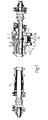
- the steering box of the invention comprises a casing 1 in which is rotatably mounted a toothed pinion 2 and a rack 3 meshing with it and axially movable within a casing; for longitudinal guidance of the rack there may conveniently be provided, at one or both ends of the said casing, a sliding bush, or else a recirculating ball bush 4 as has been shown in Figure 1.
- a support unit indicated 5 which can substantially support the thrust which the pinion applies to the rack; this support unit substantially comprises a cylindrical body 6 ( Figure 4) delimited by a substantially cylindrical surface which can be housed in a corresponding cylindrical surface 7 of the casing 1 ( Figure 1).
- the said unit substantially comprises a roller 8 provided with a central hole in which are formed rolling tracks 9 for rolling bodies constituted by balls 10 in the case of the illustrated embodiment.
- This unit includes a pair of rings 13 each of which is provided with a rolling track 14 for the rolling bodies; these rings which are mounted in contact with one another, are supported by a pin 15.
- the body 6 is provided with a cavity 16 which, as is clearly seen in Figure 5, is substantially delimited by a pair of flat opposite faces 17 and by a pair of cylindrical surfaces 18 to constitute a housing for the roller 8 and the other parts described above.
- Each of the rolling tracks 9 and 14 is formed in such a way that the contact between each ball 10 and the associated track takes place at points which belong to a pitch line indicated r in Figure 4, which is inclined by an angle different from 0° and preferably slightly different from 45°, to the equatorial plane of the roller 8. In this way the said balls are able to transmit not only radial but also axial loads from the roller 8 to the internal rings 13.
- the roller 8 is delimited externally by a pair of surfaces of revolution 19, each of which can be generated by a shape constituting substantially an arc of a circle; the radius of this latter is greater than that of the cylindrical surface 20 ( Figure 6) of the rack and the first surfaces are disposed with respect to the second in such a way that, as is clearly seen in Figure 6, the contact between the cylindrical surface 20 and each of the surfaces of revolution 19 takes place uniquely at the point, indicated P in this Figure, which is located on a plane which is inclined with respect to the equatorial plane of the roller 8.
- the two surfaces of revolution are then separated by an annular groove 21.
- the axial length of the rings 13 is slightly greater than the distance between the flat surfaces 17 which constitute a shoulder for the rings themselves, in such a way that when these rings are mounted between the said surfaces there is a predetermined axial force between the rings and the surfaces for the purpose of preventing rotation of the rings with respect to the pin 15.
- the steering box of the invention includes a resilient element, conveniently a helical spring 24 ( Figure 1), interposed between one wall 25 of the casing 1 and the body 8, for the purpose of pressing this latter towards the rack 3; beneath the body 6 there is disposed a spacer 26 defining between the first and the second a play 9 and therefore limiting the displacement of the body itself.
- a resilient element conveniently a helical spring 24 ( Figure 1), interposed between one wall 25 of the casing 1 and the body 8, for the purpose of pressing this latter towards the rack 3; beneath the body 6 there is disposed a spacer 26 defining between the first and the second a play 9 and therefore limiting the displacement of the body itself.
- the support unit described is structurally very simple and therefore can be produced with significant precision and at low cost.
- the locking of the rings 13 to prevent their rotation during operation of the rack is simply obtained by forcing these between the surfaces 17 of the casing 1;
- the assembly and axial and rotational locking of the pin 15 with respect to the body 6 is also obtained in a very simple manner by means of the slots 22 and by the plastic deformation formed in the zones 23.
- the form of the body 6, within which the cavity 16 is completely enclosed, is able to impart to the body itself a significant rigidity, in particular to prevent any relative displacement whatsoever of the slots 22 during the forcing of the rings 13 between the surfaces 17 and, simultaneously, to ensure a perfect axial guidance of the body itself within the associated cylindrical hole 17 formed in the casing 1.
Landscapes
- Engineering & Computer Science (AREA)
- Mechanical Engineering (AREA)
- General Engineering & Computer Science (AREA)
- Chemical & Material Sciences (AREA)
- Combustion & Propulsion (AREA)
- Transportation (AREA)
- Transmission Devices (AREA)
Applications Claiming Priority (2)
| Application Number | Priority Date | Filing Date | Title |
|---|---|---|---|
| IT8453881U IT8453881V0 (it) | 1984-10-02 | 1984-10-02 | Scatola sterzo per un autoveicolo |
| IT5388184U | 1984-10-02 |
Publications (1)
| Publication Number | Publication Date |
|---|---|
| EP0180017A1 true EP0180017A1 (fr) | 1986-05-07 |
Family
ID=11285753
Family Applications (1)
| Application Number | Title | Priority Date | Filing Date |
|---|---|---|---|
| EP85111513A Withdrawn EP0180017A1 (fr) | 1984-10-02 | 1985-09-12 | Boîtier de direction pour véhicule à moteur |
Country Status (3)
| Country | Link |
|---|---|
| US (1) | US4651585A (fr) |
| EP (1) | EP0180017A1 (fr) |
| IT (1) | IT8453881V0 (fr) |
Cited By (2)
| Publication number | Priority date | Publication date | Assignee | Title |
|---|---|---|---|---|
| EP0178128A3 (en) * | 1984-10-10 | 1987-06-03 | Adwest Engineering Limited | Rack and pinion steering mechanism for a motor vehicle |
| EP0367119A3 (en) * | 1988-10-27 | 1990-09-05 | Koyo Seiko Co., Ltd. | Rack and pinion steering device |
Families Citing this family (12)
| Publication number | Priority date | Publication date | Assignee | Title |
|---|---|---|---|---|
| JP3463531B2 (ja) | 1997-09-24 | 2003-11-05 | 豊田工機株式会社 | ラックアンドピニオン式舵取装置 |
| US5983742A (en) * | 1998-02-05 | 1999-11-16 | Oiles America Corporation | Rack and pinion steering device with split roller rack bar support |
| FR2798896B1 (fr) * | 1999-09-24 | 2002-02-15 | Renault | Carter pour mecanisme de direction a pignon et cremaillere |
| US6539821B2 (en) * | 2001-03-09 | 2003-04-01 | Trw Inc. | Rack and pinion steering gear with low friction yoke assembly |
| DE10314358B4 (de) * | 2003-03-31 | 2013-04-04 | Schaeffler Technologies AG & Co. KG | Zahnstangenlenkung |
| US7032470B2 (en) | 2003-06-11 | 2006-04-25 | Visteon Globsl Technologies, Inc. | Yoke bearing providing improved support |
| DE102004010819A1 (de) * | 2004-03-05 | 2005-09-22 | Ina-Schaeffler Kg | Zahnstangenlenkung |
| DE102004010821A1 (de) * | 2004-03-05 | 2005-09-22 | Ina-Schaeffler Kg | Zahnstangenlenkung |
| BRPI1102302A2 (pt) * | 2011-05-06 | 2013-01-08 | Ronen Perlin | endentamentos rolantes |
| JP2012254780A (ja) * | 2011-05-13 | 2012-12-27 | Nsk Ltd | ステアリング装置 |
| BR112015005493B1 (pt) * | 2012-09-30 | 2022-08-09 | Saint-Gobain Performance Plastics Corporation | Conjunto de forquilha de direção |
| JP6710174B2 (ja) * | 2017-03-16 | 2020-06-17 | オイレス工業株式会社 | ラックガイドおよびギア機構 |
Citations (4)
| Publication number | Priority date | Publication date | Assignee | Title |
|---|---|---|---|---|
| US3623379A (en) * | 1968-09-20 | 1971-11-30 | Cam Gears Ltd | Rack and pinion assembly |
| US4215591A (en) * | 1977-02-09 | 1980-08-05 | Bishop Arthur E | Low friction rack and pinion steering gear |
| DE2913641A1 (de) * | 1979-04-05 | 1980-10-16 | Schaeffler Ohg Industriewerk | Lagerung der zahnstange einer zahnstangenlenkung fuer kraftfahrzeuge |
| GB2093561A (en) * | 1981-02-24 | 1982-09-02 | Riv Officine Di Villar Perosa | Support element for a motor vehicle steering box rack |
Family Cites Families (7)
| Publication number | Priority date | Publication date | Assignee | Title |
|---|---|---|---|---|
| US4019784A (en) * | 1973-11-12 | 1977-04-26 | Federal-Mogul Corporation | High-impact capacity bail bearing assembly |
| FR2427522A1 (fr) * | 1978-05-30 | 1979-12-28 | Renault | Poussoir de direction a cremaillere |
| GB2036240B (en) * | 1978-11-27 | 1982-12-15 | Cam Gears Ltd | Variable ratio rack and pinion gear |
| US4337781A (en) * | 1980-03-31 | 1982-07-06 | Allis-Chalmers Corporation | Roller support for cage sweep mechanism |
| CH647052A5 (de) * | 1980-07-17 | 1984-12-28 | Agathon Ag Maschf | Waelzgelagerte laengsfuehrung. |
| GB2096729B (en) * | 1981-03-24 | 1984-07-18 | Cam Gears Ltd | A rack bar and pinion assembly and a steering gear including such an assembly |
| US4531603A (en) * | 1984-01-09 | 1985-07-30 | General Motors Corporation | Rack and pinion steering gear with adjustable low friction anti-roll rack bearing |
-
1984
- 1984-10-02 IT IT8453881U patent/IT8453881V0/it unknown
- 1984-12-03 US US06/677,493 patent/US4651585A/en not_active Expired - Fee Related
-
1985
- 1985-09-12 EP EP85111513A patent/EP0180017A1/fr not_active Withdrawn
Patent Citations (4)
| Publication number | Priority date | Publication date | Assignee | Title |
|---|---|---|---|---|
| US3623379A (en) * | 1968-09-20 | 1971-11-30 | Cam Gears Ltd | Rack and pinion assembly |
| US4215591A (en) * | 1977-02-09 | 1980-08-05 | Bishop Arthur E | Low friction rack and pinion steering gear |
| DE2913641A1 (de) * | 1979-04-05 | 1980-10-16 | Schaeffler Ohg Industriewerk | Lagerung der zahnstange einer zahnstangenlenkung fuer kraftfahrzeuge |
| GB2093561A (en) * | 1981-02-24 | 1982-09-02 | Riv Officine Di Villar Perosa | Support element for a motor vehicle steering box rack |
Cited By (2)
| Publication number | Priority date | Publication date | Assignee | Title |
|---|---|---|---|---|
| EP0178128A3 (en) * | 1984-10-10 | 1987-06-03 | Adwest Engineering Limited | Rack and pinion steering mechanism for a motor vehicle |
| EP0367119A3 (en) * | 1988-10-27 | 1990-09-05 | Koyo Seiko Co., Ltd. | Rack and pinion steering device |
Also Published As
| Publication number | Publication date |
|---|---|
| US4651585A (en) | 1987-03-24 |
| IT8453881V0 (it) | 1984-10-02 |
Similar Documents
| Publication | Publication Date | Title |
|---|---|---|
| EP0180017A1 (fr) | Boîtier de direction pour véhicule à moteur | |
| JP3015202B2 (ja) | 軸受組立体 | |
| US6343671B1 (en) | Actuator for generating an additional steering angle for road vehicles | |
| US4854917A (en) | Tripot type constant velocity universal joint | |
| US4369387A (en) | Electric drive unit | |
| KR20030077008A (ko) | 선형 가이드 | |
| US5503239A (en) | Variable gear ratio steering device | |
| EP2371675B1 (fr) | Dispositif de direction assistée électrique | |
| US5709605A (en) | Shaft coupling | |
| EP1087883B1 (fr) | Perfectionnements relatifs aux systemes electriques de direction assistee | |
| US6000491A (en) | Electric power steering apparatus having steering torque sensor integrally assembled in steering device with variable steering ratio | |
| US5489004A (en) | Variable ratio steering system | |
| US4724717A (en) | Rack shaft supporting device | |
| US6516680B1 (en) | Power steering apparatus | |
| GB2274818A (en) | Variable ratio steering system. | |
| EP0491801B1 (fr) | Differentiel | |
| US6227064B1 (en) | Power steering apparatus | |
| WO2019002888A1 (fr) | Ensemble boîte de vitesses | |
| US4688902A (en) | Anti-backlash cam | |
| EP0425238A1 (fr) | Arbre télescopique pour la transmission des moments de torsion | |
| US4222619A (en) | Device for transforming a rotational movement into a linear movement | |
| KR20230173484A (ko) | 스티어링 액츄에이터 및 스티어링 액츄에이터의 감속기 기어간 초기 유격 조정 방법 | |
| GB2093561A (en) | Support element for a motor vehicle steering box rack | |
| US6234271B1 (en) | Power steering device | |
| EP1304504B1 (fr) | Dispositif de modification de vitesse à vis sans fin et direction assistée électrique |
Legal Events
| Date | Code | Title | Description |
|---|---|---|---|
| PUAI | Public reference made under article 153(3) epc to a published international application that has entered the european phase |
Free format text: ORIGINAL CODE: 0009012 |
|
| AK | Designated contracting states |
Kind code of ref document: A1 Designated state(s): DE FR GB SE |
|
| 17P | Request for examination filed |
Effective date: 19860908 |
|
| 17Q | First examination report despatched |
Effective date: 19870504 |
|
| STAA | Information on the status of an ep patent application or granted ep patent |
Free format text: STATUS: THE APPLICATION HAS BEEN WITHDRAWN |
|
| 18W | Application withdrawn |
Withdrawal date: 19871009 |
|
| RIN1 | Information on inventor provided before grant (corrected) |
Inventor name: DONN, VITTORIO Inventor name: COGNO, PIETRO |