EP0180018A2 - Dispositif pour appliquer des housses à des corps, spécialement à des dossiers pour automobiles ainsi qu'un procédé pour couvrir un corps à l'aide d'un tel dispositif - Google Patents
Dispositif pour appliquer des housses à des corps, spécialement à des dossiers pour automobiles ainsi qu'un procédé pour couvrir un corps à l'aide d'un tel dispositif Download PDFInfo
- Publication number
- EP0180018A2 EP0180018A2 EP85111679A EP85111679A EP0180018A2 EP 0180018 A2 EP0180018 A2 EP 0180018A2 EP 85111679 A EP85111679 A EP 85111679A EP 85111679 A EP85111679 A EP 85111679A EP 0180018 A2 EP0180018 A2 EP 0180018A2
- Authority
- EP
- European Patent Office
- Prior art keywords
- cassette
- fuselage
- backrest
- bracket
- holding device
- Prior art date
- Legal status (The legal status is an assumption and is not a legal conclusion. Google has not performed a legal analysis and makes no representation as to the accuracy of the status listed.)
- Granted
Links
Images


Classifications
-
- B—PERFORMING OPERATIONS; TRANSPORTING
- B65—CONVEYING; PACKING; STORING; HANDLING THIN OR FILAMENTARY MATERIAL
- B65B—MACHINES, APPARATUS OR DEVICES FOR, OR METHODS OF, PACKAGING ARTICLES OR MATERIALS; UNPACKING
- B65B5/00—Packaging individual articles in containers or receptacles, e.g. bags, sacks, boxes, cartons, cans, jars
- B65B5/04—Packaging single articles
-
- B—PERFORMING OPERATIONS; TRANSPORTING
- B68—SADDLERY; UPHOLSTERY
- B68G—METHODS, EQUIPMENT, OR MACHINES FOR USE IN UPHOLSTERING; UPHOLSTERY NOT OTHERWISE PROVIDED FOR
- B68G7/00—Making upholstery
- B68G7/05—Covering or enveloping cores of pads
-
- Y—GENERAL TAGGING OF NEW TECHNOLOGICAL DEVELOPMENTS; GENERAL TAGGING OF CROSS-SECTIONAL TECHNOLOGIES SPANNING OVER SEVERAL SECTIONS OF THE IPC; TECHNICAL SUBJECTS COVERED BY FORMER USPC CROSS-REFERENCE ART COLLECTIONS [XRACs] AND DIGESTS
- Y10—TECHNICAL SUBJECTS COVERED BY FORMER USPC
- Y10T—TECHNICAL SUBJECTS COVERED BY FORMER US CLASSIFICATION
- Y10T29/00—Metal working
- Y10T29/48—Upholstered article making
- Y10T29/481—Method
-
- Y—GENERAL TAGGING OF NEW TECHNOLOGICAL DEVELOPMENTS; GENERAL TAGGING OF CROSS-SECTIONAL TECHNOLOGIES SPANNING OVER SEVERAL SECTIONS OF THE IPC; TECHNICAL SUBJECTS COVERED BY FORMER USPC CROSS-REFERENCE ART COLLECTIONS [XRACs] AND DIGESTS
- Y10—TECHNICAL SUBJECTS COVERED BY FORMER USPC
- Y10T—TECHNICAL SUBJECTS COVERED BY FORMER US CLASSIFICATION
- Y10T29/00—Metal working
- Y10T29/48—Upholstered article making
- Y10T29/486—Cover stretching
-
- Y—GENERAL TAGGING OF NEW TECHNOLOGICAL DEVELOPMENTS; GENERAL TAGGING OF CROSS-SECTIONAL TECHNOLOGIES SPANNING OVER SEVERAL SECTIONS OF THE IPC; TECHNICAL SUBJECTS COVERED BY FORMER USPC CROSS-REFERENCE ART COLLECTIONS [XRACs] AND DIGESTS
- Y10—TECHNICAL SUBJECTS COVERED BY FORMER USPC
- Y10T—TECHNICAL SUBJECTS COVERED BY FORMER US CLASSIFICATION
- Y10T29/00—Metal working
- Y10T29/49—Method of mechanical manufacture
- Y10T29/49826—Assembling or joining
- Y10T29/49863—Assembling or joining with prestressing of part
- Y10T29/4987—Elastic joining of parts
- Y10T29/49872—Confining elastic part in socket
-
- Y—GENERAL TAGGING OF NEW TECHNOLOGICAL DEVELOPMENTS; GENERAL TAGGING OF CROSS-SECTIONAL TECHNOLOGIES SPANNING OVER SEVERAL SECTIONS OF THE IPC; TECHNICAL SUBJECTS COVERED BY FORMER USPC CROSS-REFERENCE ART COLLECTIONS [XRACs] AND DIGESTS
- Y10—TECHNICAL SUBJECTS COVERED BY FORMER USPC
- Y10T—TECHNICAL SUBJECTS COVERED BY FORMER US CLASSIFICATION
- Y10T29/00—Metal working
- Y10T29/53—Means to assemble or disassemble
- Y10T29/53657—Means to assemble or disassemble to apply or remove a resilient article [e.g., tube, sleeve, etc.]
Definitions
- the present invention relates to a device for applying covers to fuselages, in particular in the case of car seat backrests, as described in the introduction to claim 1.
- the invention further relates to a method for covering a fuselage by means of such a device in accordance with the introduction of the first method claim.
- FR 2 027 533 already discloses a largely mechanical device for covering furniture.
- This device also uses one a cover turned to the left to surround the cassette, through which the piece of furniture is pressed completely with the aid of working cylinders, the cover being turned.
- the cassette is divided and designed with moving parts, since practically all furniture is profiled in some way, that is to say irregularly.
- a tight fitting of tight-fitting and in particular not too extensible covers is not possible with such a device, particularly in the case of furniture with a very irregular design, in which the parts taper once, expand once, are convex and are concave.
- the cassette parts are deflected by protruding parts that are first coated, without being able to adapt to a subsequent taper or the like.
- the joint articulation of the cassette parts on one or two common pivot axes is disadvantageous for these reasons, especially since the cassette parts are still straight.
- the upholstered furniture may first have to be lifted vertically from a deep position in order to be able to be removed from the cassette, which is time-consuming and exhausting. Attaching additional equipment, ie parts that go beyond a covering, may also be difficult or even impossible. Switching to other furniture is undoubtedly costly and time-consuming, if at all possible in certain cases, and in most cases may require the entire cassette to be replaced.
- the object of the present invention is therefore to provide a device which avoids the need manual overturning and fully automatic overturning is permitted, is simple and quick to operate, has low manufacturing costs, is extremely reliable and can be easily, quickly, easily and economically converted to different hulls.
- the object of the invention is also to provide a method for covering a fuselage by means of such a device.
- the invention provides in particular a device as specified in the characterizing part of claim 1.
- the method for covering a fuselage by means of such a device emerges from the characterizing part of the first method claim.
- Fig. 1 shows a mounting device with a frame 10, a cassette 12 attached to this for fixing the position of one end of a backrest, a mobile holding device 14 for the other end of the backrest and movable front and rear pressure brackets 16, 18.
- the frame 10 has Installation and assembly of two foot beams 20, which are held together by a cross beam 22 and a cross strut 24. On the crossbar 24 two upstanding stands 26 are attached, on which the cassette 12 is removably attached.
- the frame also has two protruding from the foot beams Side columns 28, which are connected to one another at the top by a yoke 30. Between the yoke 30 and the crossbeam 22, two lateral guide rods 32 are fastened, along which the holding device 14 and the pressure bracket 16, 18 travel.
- the holding device 14 consists of two guide shoes 34 and a frame 36 connecting the latter, on which displaceable sliding shoes 38 are arranged.
- the latter are preferably provided with retaining bolts (not shown) and have fastenings for exchangeable and length-adjustable holders 40.
- the latter have fastening members for a backrest to be covered, for example as recesses 42.
- the holding device 14 can be moved in the longitudinal direction of the guide rods with the aid of a working cylinder 44, which is attached to the yoke of the frame.
- the holding device is fastened to the piston rod 46 of the working cylinder with the aid of a fastening device 48. This is preferably designed such that it allows a variable fixing in the longitudinal direction of the piston rod in order to adapt the position of the holding device to backrests of different lengths.
- the pressure clamps 16, 18 are anchored to fastening members 50, which in turn are fastened to a carriage 52.
- the carriage consists of two guide shoes 54, a double frame 56 and an exposed square bar 58 which extends between the guide shoes.
- the fastening members 50 are fixed to the rod 58 with the aid of a square sleeve 60 which is provided with a locking bolt 62.
- a square rod 64 protrudes from the square sleeve and carries the square body 66 of the fastening elements.
- the fuselage is displaceable on the rod 64 and is locked in position by means of fastening bolts 68.
- Fastening members 70 for articulating the brackets 16, 18 and fastening members 72 made of flat iron for pressure cylinders 74, 76 of the brackets 16, 18 are fastened to the fuselages.
- the pressure cylinders 74 are on the front bracket 16 and the pressure cylinders 76 fixed to the rear bracket 18.
- the front bracket 16 consists of the actual bracket 16, which is inserted into tubular leg 78.
- the rear bracket 18 is inserted into tubular leg 80. In this way it is possible to convert the mounting device to backrests of different widths by exchanging the pressure brackets 16, 18 and moving the fastening elements laterally into the correct position.
- the fastening elements with the pressure brackets and the carriage 52 can be moved by means of a double-acting working cylinder 82 which is fastened to the yoke 30.
- the piston rod 84 of the working cylinder is fastened to the carriage 52 with the aid of a fastening device 86, so that the carriage position can be adjusted in the longitudinal direction of the piston rod.
- the device according to the invention is used in the following way.
- a coating which is turned inside out and is open on one side is slipped over the cassette 12 and the pressure bracket 16, 18.
- a backrest is then placed at one end on the cassette and attached to the holders 40 at the other end.
- the holders can be designed such that they interact with mounting elements located on the backrest.
- the holders are preferably provided with quick fastening devices for the backrest, so that the backrest can be displaced in the longitudinal direction without detaching from the holders.
- Such quick fastening members can be various spring-loaded locking members or can simply be an extension inside the recesses 42. In this way, time-consuming screwing of the backrest is avoided.
- the double-acting working cylinder 44 is actuated, which presses out the piston rod 46, the holding device 14 and the backrest being carried along, so that the one backrest end is pressed into the cassette 12 until it has reached the bottom of the cassette.
- the backrest pulls the cover with it into the cassette, turning it correctly and sliding it over the backrest part located in the cassette.
- the second double-acting working cylinder 82 is actuated, which retracts the piston rod 84, the carriage 52, the fastening elements 50 and the brackets 16, 18 being moved in the direction of the other backrest end.
- the pressure cylinders 74 pull the front pressure bracket against the front of the backrest, while the pressure cylinders 76 press the rear pressure bracket 18 against the back of the backrest.
- the brackets 16, 18 are in the turning fold of the partially turned cover and cause a continuous turning during their movement towards the other end of the backrest. At the end of the piston movement, the cover is completely turned and surrounds the backrest in the correct turned position.
- the working cylinder 82 is activated in the opposite direction and thereby pulls the pressure brackets 16, 18 back into their starting position near the cassette 12. Then the working cylinder 44 is actuated in the opposite direction and pulls the backrest out of the cassette 12, whereupon the backrest can be released from the holders 40 and a new working cycle can begin.
- the mounting device according to the invention can be used for backrests of different sizes.
- the cassette 12 and the pressure clamps 16, 18 are exchanged for those of a suitable size and the square sleeves 60 are moved into the correct lateral position.
- the sliding shoes 38 are moved laterally with the holders 40 in accordance with the new backrest width.
- the brackets 40 may be replaced with others that fit the new backrest.
- the holding device 14 is adjusted in the height direction with the aid of the fastening device 48 in accordance with the length of the new backrest.
- the brackets 16, 18 can possibly also be adjusted in the vertical direction using the fastening device 86 if required.
- the assembly device shown and described works with the aid of a number of working cylinders, which are preferably operated pneumatically.
- the working cylinders are preferably sequence-controlled by a control center, / so that after the covering and backrest have been straightened and attached, all working moments can be carried out in a sequence by activating a single starting control.
- the device can also be operated with the aid of hydraulic cylinders and other drive devices, for example electric motors. Manual operation using levers and / or pedals is also conceivable. It it is also possible to combine any different power sources for the mounting device according to the invention.
- the movement of the brackets 16, 18 and the holding device 14 can be carried out with the aid of pneumatic cylinders 44, 82, while the brackets 16, 18 are pressed against the sides of the backrest by other means, for example spring force or suitable counterweights.
- the bow shape does not necessarily have to be the simple shape shown.
- the brackets can be curved, for example, so that they follow the contour of the backrest.
- the brackets can also have a plate that follows the contour of the backrest.
- the stirrup legs do not necessarily have to be arranged on the backrest sides, but can also follow the backrest front and back side, with a part of the stirrup protruding laterally outside the leg. However, this is often associated with difficulties, since the brackets should be able to follow the contour of the backrest throughout and legs arranged at the end are therefore preferable.
- Fig. 1 shows a standing mounting device with the cassette at the lower end. It is of course also possible to carry out the mounting device horizontally. It can preferably be provided with a support for the backrest, which is automatically removed after the backrest has been inserted into the cassette. Furthermore, the device can be carried upright with a cassette arranged in the upper region or in another way.
- the pressure cylinders and in particular the cylinders 74 are preferably double-acting. This makes it possible after pulling a cover on the backrest to pull the bracket 16 away from the latter, so that it is not on it during its return movement into the off position current situation is present.
- the mounting device preferably has stop devices for the travel movements of the holding device or the pressure bracket. These can preferably be arranged after the guide rods. Furthermore, limit switches are advantageously arranged at the desired end positions of the various movements. Such limit switches can trigger a pulse to stop a travel movement and / or to start a new one. Such limit switches can advantageously belong to a sequence control system for two or more working moments. With the help of limit switches and other organs for the sequence control, it may be possible to apply the cover in a single operation without the involvement of the operating personnel.
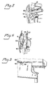
- FIG. 3 shows a preferred embodiment of holders 40 with downward-pointing claws 101, 102, which are provided on their mutually facing sides with shoulders 103 and bevels 104, e.g. to hold transverse bars of a backrest securely.
- At least one of the claws is acted upon by a spring and / or a pressure-actuated working cylinder (not shown) in a manner known per se, which holds the fuselage securely during the work processes and releases it at the end, at least one of the claws preferably being deflected or pivoted away.
- the two sides are connected to one another via a base, which may possibly only be in the form of two spacers 105, which is advantageous, e.g. Arrange guide sleeves 106 for headrests and neckrests in localization instructions 107.
- a base which may possibly only be in the form of two spacers 105, which is advantageous, e.g. Arrange guide sleeves 106 for headrests and neckrests in localization instructions 107.
- the sleeves When attaching a covering provided with openings for these sleeves, the sleeves are guided through the openings and then automatically pressed into the fuselage as the fuselage moves downward.
- the upper cassette corners may also be cut out as shown in FIG. 5 for ease of access to the location instructions.
- each stirrup bar is provided in the middle with a bend 110 that fits into the recess.
- both stirrups in their starting position can be pressed by spring means (not shown) against the associated stop 109, the stirrup web lying within the relevant cassette side plane. Since the brackets are made of round iron, the cover glides smoothly past them while practically not touching the sides of the cassette. A perfect starting point and low friction are guaranteed.
- Fig. 4 indicates how advantageous the special temples can be adapted to different hull shapes.
- the stirrups follow any shape of trunk with a tight fit and are therefore low in friction and tension, which in turn allows particularly close-fitting covers to be used, as is desired, for example, in car seat backrests.
- the strap webs and leg attachments can be designed as interchangeable parts, the leg attachments simply being insertable into, or onto, the preferably straight, pivotably hinged strap leg portions are slidably provided.
- the invention also allows an advantageous, simple and quick attachment of additional equipment in a comfortable and correct working position for the staff who never have to bend down or have to carry out heavy work movements.
- the upward movement of the brackets can be stopped at any height, so that one side of the cover can be connected to the other, which e.g. this is done by connecting sewn-in cross bars on one inside of the cover with those on the other inside of the cover by hooks or the like.
- the advantage of the flat, fixed cassette at the correct height is the advantage of the flat, fixed cassette at the correct height.
- the cassette thus serves as a stop and holder for a fuselage, while the brackets practically take care of the covering.
- the cover can also extend into a bracket, e.g. as shown in Fig. 4. It is therefore possible to apply the tightest covers on the most difficult hulls with minimal friction.
- both brackets 16, 18 can be actuated pneumatically and, for example, via reducing valves be adjustable. In this way, it no longer matters how the two main sides of an object to be covered are designed, ie you can turn or choose the sides as you wish.
- the device according to the invention can also be arranged tiltably in a manner known per se.
Landscapes
- Engineering & Computer Science (AREA)
- Mechanical Engineering (AREA)
- Manufacturing & Machinery (AREA)
- Seats For Vehicles (AREA)
- Body Structure For Vehicles (AREA)
- Automobile Manufacture Line, Endless Track Vehicle, Trailer (AREA)
- Electrostatic Spraying Apparatus (AREA)
- Vehicle Step Arrangements And Article Storage (AREA)
- Fittings On The Vehicle Exterior For Carrying Loads, And Devices For Holding Or Mounting Articles (AREA)
- Chairs For Special Purposes, Such As Reclining Chairs (AREA)
- Chair Legs, Seat Parts, And Backrests (AREA)
Priority Applications (1)
| Application Number | Priority Date | Filing Date | Title |
|---|---|---|---|
| AT85111679T ATE51830T1 (de) | 1984-09-20 | 1985-09-16 | Vorrichtung zum anbringen von ueberzuegen an ruempfen, insbesondere bei autositzrueckenlehnen, sowie verfahren zum ueberziehen eines rumpfes mittels einer solchen vorrichtung. |
Applications Claiming Priority (2)
| Application Number | Priority Date | Filing Date | Title |
|---|---|---|---|
| SE8404706 | 1984-09-20 | ||
| SE8404706A SE449689B (sv) | 1984-09-20 | 1984-09-20 | Anordning for montering av kledslar pa en stomme |
Publications (3)
| Publication Number | Publication Date |
|---|---|
| EP0180018A2 true EP0180018A2 (fr) | 1986-05-07 |
| EP0180018A3 EP0180018A3 (en) | 1987-05-20 |
| EP0180018B1 EP0180018B1 (fr) | 1990-04-11 |
Family
ID=20357075
Family Applications (1)
| Application Number | Title | Priority Date | Filing Date |
|---|---|---|---|
| EP85111679A Expired - Lifetime EP0180018B1 (fr) | 1984-09-20 | 1985-09-16 | Dispositif pour appliquer des housses à des corps, spécialement à des dossiers pour automobiles ainsi qu'un procédé pour couvrir un corps à l'aide d'un tel dispositif |
Country Status (7)
| Country | Link |
|---|---|
| US (1) | US4675962A (fr) |
| EP (1) | EP0180018B1 (fr) |
| AT (1) | ATE51830T1 (fr) |
| CA (1) | CA1266166A (fr) |
| DE (1) | DE3577075D1 (fr) |
| ES (1) | ES8608837A1 (fr) |
| SE (1) | SE449689B (fr) |
Cited By (3)
| Publication number | Priority date | Publication date | Assignee | Title |
|---|---|---|---|---|
| EP0375396B1 (fr) * | 1988-12-23 | 1992-04-15 | Magneti Marelli Electrical Limited | Moteurs de démarrage |
| EP0737645A3 (fr) * | 1995-01-09 | 1997-05-02 | Riboldi Servo Matic S R L | Presse d'habillage pour éléments de rembourrage |
| EP2398357A4 (fr) * | 2009-02-23 | 2012-08-08 | L & P Property Management Co | Création de tension dans une unité de siège par prémoulage d'un cadre |
Families Citing this family (19)
| Publication number | Priority date | Publication date | Assignee | Title |
|---|---|---|---|---|
| JPH0739545Y2 (ja) * | 1988-04-20 | 1995-09-13 | デルタ工業株式会社 | 自動車用シートの組立装置 |
| AU616235B2 (en) * | 1989-02-01 | 1991-10-24 | Tachi-S Co., Ltd. | Apparatus for forming vehile seat |
| US4986055A (en) * | 1990-02-16 | 1991-01-22 | Machine Design Systems, Inc. | Cushion compression machine for compressing a cushion and applying a cover to the cushion |
| US5199144A (en) * | 1991-05-30 | 1993-04-06 | Tachi-S Co. Ltd. | Apparatus for affixing covering member to armrest body used for automotive seat |
| US5180460A (en) * | 1991-11-12 | 1993-01-19 | Findlay Industries | Inverting seat covers |
| US5327629A (en) * | 1991-11-12 | 1994-07-12 | Findlay Industries | Inverting seat covers |
| US5253401A (en) * | 1991-11-12 | 1993-10-19 | Findlay Industries | Apparatus for inverting seat covers |
| US5774965A (en) * | 1993-03-02 | 1998-07-07 | Machine Design Systems, Inc. | Apparatus for inserting an insert into a cover |
| US5398482A (en) * | 1993-03-10 | 1995-03-21 | General Motors Corporation | Seat skinning apparatus and method |
| US5345661A (en) * | 1993-05-03 | 1994-09-13 | General Motors Corporation | Seat skinning and method |
| US5398393A (en) * | 1994-02-28 | 1995-03-21 | Labor Aiding Systems, Inc. | Seat cushion and cover assembly apparatus |
| US5457864A (en) * | 1994-04-07 | 1995-10-17 | Tachi-S Co., Ltd. | Device for affixing a trim cover assembly over a cushion member for an automotive seat |
| US5586377A (en) * | 1994-11-30 | 1996-12-24 | Tachi-S Co., Ltd | System for covering a cushion member with a trim cover assembly |
| US5669130A (en) * | 1995-10-12 | 1997-09-23 | Tachi-S Co., Ltd. | Device for assembling a seat back of a seat |
| US6434806B1 (en) | 1999-07-19 | 2002-08-20 | Lms Walt, Inc. | Machine for installing flexible covers on seat cushions having sliding stanchion carriage for closely following the contour of the seat cushion |
| US6199251B1 (en) * | 2000-02-01 | 2001-03-13 | Milliken & Company | Elastomeric hoop attachment device |
| US6880216B2 (en) * | 2001-02-14 | 2005-04-19 | Automated Solutions, Inc. | Seat assembly machine with independently moveable headrest alignment |
| US6780177B2 (en) * | 2002-08-27 | 2004-08-24 | Board Of Trustees Of The University Of Arkansas | Conductive interstitial thermal therapy device |
| CN105500274B (zh) * | 2016-01-22 | 2018-01-19 | 上海卢潘涵五金模具有限公司 | 一种靠背压机 |
Family Cites Families (7)
| Publication number | Priority date | Publication date | Assignee | Title |
|---|---|---|---|---|
| DD91196A (fr) * | ||||
| US958011A (en) * | 1909-06-25 | 1910-05-17 | Aime Rothberg | Apparatus for making leather-covered cushioned-seats for chairs. |
| US3438108A (en) * | 1966-07-25 | 1969-04-15 | Alsco Inc | Apparatus for assembling and securing components of a furniture cushion |
| DE2035288C3 (de) * | 1970-07-16 | 1975-08-14 | Christof Grauff Kg Maschinenfabrik, 7518 Bretten | Vorrichtung zum Beziehen von Polsterkissen |
| DD128711B1 (de) * | 1976-03-31 | 1980-12-10 | Anneliese Jacob | Geraet zum beziehen von steppdecken |
| US4385427A (en) * | 1980-12-08 | 1983-05-31 | Fraiser Frederick F | Machine for installing upholstery covers |
| DD228798A1 (de) * | 1984-08-24 | 1985-10-23 | Thueringer Moebel | Vorrichtung zum beziehen von gepolsterten teilen |
-
1984
- 1984-09-20 SE SE8404706A patent/SE449689B/sv not_active IP Right Cessation
-
1985
- 1985-09-16 AT AT85111679T patent/ATE51830T1/de not_active IP Right Cessation
- 1985-09-16 DE DE8585111679T patent/DE3577075D1/de not_active Expired - Lifetime
- 1985-09-16 EP EP85111679A patent/EP0180018B1/fr not_active Expired - Lifetime
- 1985-09-17 CA CA000490903A patent/CA1266166A/fr not_active Expired - Lifetime
- 1985-09-19 ES ES547101A patent/ES8608837A1/es not_active Expired
- 1985-09-19 US US06/777,537 patent/US4675962A/en not_active Expired - Fee Related
Cited By (3)
| Publication number | Priority date | Publication date | Assignee | Title |
|---|---|---|---|---|
| EP0375396B1 (fr) * | 1988-12-23 | 1992-04-15 | Magneti Marelli Electrical Limited | Moteurs de démarrage |
| EP0737645A3 (fr) * | 1995-01-09 | 1997-05-02 | Riboldi Servo Matic S R L | Presse d'habillage pour éléments de rembourrage |
| EP2398357A4 (fr) * | 2009-02-23 | 2012-08-08 | L & P Property Management Co | Création de tension dans une unité de siège par prémoulage d'un cadre |
Also Published As
| Publication number | Publication date |
|---|---|
| US4675962A (en) | 1987-06-30 |
| SE449689B (sv) | 1987-05-18 |
| CA1266166A (fr) | 1990-02-27 |
| ATE51830T1 (de) | 1990-04-15 |
| SE8404706L (sv) | 1986-03-21 |
| SE8404706D0 (sv) | 1984-09-20 |
| EP0180018B1 (fr) | 1990-04-11 |
| EP0180018A3 (en) | 1987-05-20 |
| ES547101A0 (es) | 1986-08-01 |
| DE3577075D1 (de) | 1990-05-17 |
| ES8608837A1 (es) | 1986-08-01 |
Similar Documents
| Publication | Publication Date | Title |
|---|---|---|
| EP0180018B1 (fr) | Dispositif pour appliquer des housses à des corps, spécialement à des dossiers pour automobiles ainsi qu'un procédé pour couvrir un corps à l'aide d'un tel dispositif | |
| DE2402411A1 (de) | Aufnahmehalterung fuer sportstaettenpflegegeraete oder dergleichen | |
| DE8605875U1 (de) | Montageeinrichtung für Karosserieteile von Kraftfahrzeugen | |
| DE10038511A1 (de) | Längs-Bearbeitungs-Maschine für Wellpappe-Bahnen | |
| DE1752558A1 (de) | Streckziehvorrichtung | |
| DE2132021A1 (de) | Vorrichtung,vorzugsweise Richtvorrichtung zum Ausfuehren der Operationen fuer das Ausbessern und Zurueckverformen bzw.Zurueckfuehren auf die urspruengliche Form von z.B.verbeulten oder beschaedigten Blechen von Karosserien,insbesondere von Kraftfahrzeugen | |
| DE2430569A1 (de) | Vorrichtung zum aufbringen einer verbindungsmuffe auf zwei stangen, insbesondere bewehrungsstaehle | |
| DE3633539C2 (de) | Vorrichtung zum Einbringen von Metallösen in die Planen von Lastkraftwagen od.dgl. | |
| DE2953000C1 (de) | Zangeneinheit fuer eine Schuhzwickmaschine | |
| EP0878251A1 (fr) | Presse-transfer avec un support latéral sur une table mobile pour les porte-pièce | |
| DE1760704A1 (de) | Vorrichtung zum Straffen des Spitzen- und Vorfussteiles eines Schuhschaftes ueber die entsprechenden Leistenteile | |
| DE9315560U1 (de) | Ausbeulvorrichtung | |
| DE60204925T2 (de) | Spannvorrichtung | |
| DE1148960B (de) | Maschine zum Formen von Blechstreifen | |
| DE1777227B1 (de) | Vorrichtung zum Richten insbesondere von Kraftfahrzeugkarosserien | |
| DE4111398A1 (de) | Stanzpresse fuer blech | |
| DE2133594C3 (de) | Vorrichtung zum Reparieren deformierter Gehäuse aus verformbaren Material | |
| DE1685202C (de) | Beziehpresse mit Bezugwende- und Überziehvorrichtung zum Beziehen von Teilen von Polstermöbeln | |
| DE1186019B (de) | Maschine zum Falzen von Tuerueberlappungsflanschen | |
| DE3224266A1 (de) | Klemmvorrichtung | |
| DE1685201C (de) | Polstersessel-Montagebock | |
| DE1659648C (de) | Verfahren zum Herstellen und Zusammenbauen von Rolladenhohlstäben und Presse zur Durchführung des Verfahrens | |
| DE308260C (fr) | ||
| DE1777227C (de) | Vorrichtung zum Richten insbesondere von Kraftfahrzeugkarosserien | |
| DE66101C (de) | Maschine zur Herstellung von Eckverbindungen an Schachteln mittels rinnenförmiger BJechwinkel |
Legal Events
| Date | Code | Title | Description |
|---|---|---|---|
| PUAI | Public reference made under article 153(3) epc to a published international application that has entered the european phase |
Free format text: ORIGINAL CODE: 0009012 |
|
| AK | Designated contracting states |
Kind code of ref document: A2 Designated state(s): AT BE CH DE FR GB IT LI NL SE |
|
| 17P | Request for examination filed |
Effective date: 19860707 |
|
| PUAL | Search report despatched |
Free format text: ORIGINAL CODE: 0009013 |
|
| AK | Designated contracting states |
Kind code of ref document: A3 Designated state(s): AT BE CH DE FR GB IT LI NL SE |
|
| 17Q | First examination report despatched |
Effective date: 19881005 |
|
| GRAA | (expected) grant |
Free format text: ORIGINAL CODE: 0009210 |
|
| AK | Designated contracting states |
Kind code of ref document: B1 Designated state(s): AT BE CH DE FR GB IT LI NL SE |
|
| PG25 | Lapsed in a contracting state [announced via postgrant information from national office to epo] |
Ref country code: SE Effective date: 19900411 |
|
| REF | Corresponds to: |
Ref document number: 51830 Country of ref document: AT Date of ref document: 19900415 Kind code of ref document: T |
|
| REF | Corresponds to: |
Ref document number: 3577075 Country of ref document: DE Date of ref document: 19900517 |
|
| ITF | It: translation for a ep patent filed | ||
| ET | Fr: translation filed | ||
| GBT | Gb: translation of ep patent filed (gb section 77(6)(a)/1977) | ||
| PLBE | No opposition filed within time limit |
Free format text: ORIGINAL CODE: 0009261 |
|
| STAA | Information on the status of an ep patent application or granted ep patent |
Free format text: STATUS: NO OPPOSITION FILED WITHIN TIME LIMIT |
|
| 26N | No opposition filed | ||
| ITTA | It: last paid annual fee | ||
| PGFP | Annual fee paid to national office [announced via postgrant information from national office to epo] |
Ref country code: GB Payment date: 19950731 Year of fee payment: 11 |
|
| PGFP | Annual fee paid to national office [announced via postgrant information from national office to epo] |
Ref country code: CH Payment date: 19950802 Year of fee payment: 11 |
|
| PGFP | Annual fee paid to national office [announced via postgrant information from national office to epo] |
Ref country code: FR Payment date: 19950811 Year of fee payment: 11 |
|
| PGFP | Annual fee paid to national office [announced via postgrant information from national office to epo] |
Ref country code: BE Payment date: 19950818 Year of fee payment: 11 |
|
| PGFP | Annual fee paid to national office [announced via postgrant information from national office to epo] |
Ref country code: AT Payment date: 19950914 Year of fee payment: 11 |
|
| PGFP | Annual fee paid to national office [announced via postgrant information from national office to epo] |
Ref country code: NL Payment date: 19950929 Year of fee payment: 11 |
|
| PGFP | Annual fee paid to national office [announced via postgrant information from national office to epo] |
Ref country code: DE Payment date: 19951125 Year of fee payment: 11 |
|
| PG25 | Lapsed in a contracting state [announced via postgrant information from national office to epo] |
Ref country code: GB Effective date: 19960916 Ref country code: AT Effective date: 19960916 |
|
| PG25 | Lapsed in a contracting state [announced via postgrant information from national office to epo] |
Ref country code: LI Effective date: 19960930 Ref country code: FR Effective date: 19960930 Ref country code: CH Effective date: 19960930 Ref country code: BE Effective date: 19960930 |
|
| BERE | Be: lapsed |
Owner name: TILLNER ALFRED Effective date: 19960930 Owner name: HEDENBER CONNY Effective date: 19960930 |
|
| PG25 | Lapsed in a contracting state [announced via postgrant information from national office to epo] |
Ref country code: NL Effective date: 19970401 |
|
| GBPC | Gb: european patent ceased through non-payment of renewal fee |
Effective date: 19960916 |
|
| REG | Reference to a national code |
Ref country code: CH Ref legal event code: PL |
|
| NLV4 | Nl: lapsed or anulled due to non-payment of the annual fee |
Effective date: 19970401 |
|
| PG25 | Lapsed in a contracting state [announced via postgrant information from national office to epo] |
Ref country code: DE Effective date: 19970603 |
|
| REG | Reference to a national code |
Ref country code: FR Ref legal event code: ST |
|
| REG | Reference to a national code |
Ref country code: FR Ref legal event code: ST |