EP0180034A1 - Dispositif avec deux générateurs de Hall pour mesurer le gradient de champs magnétiques - Google Patents
Dispositif avec deux générateurs de Hall pour mesurer le gradient de champs magnétiques Download PDFInfo
- Publication number
- EP0180034A1 EP0180034A1 EP85112087A EP85112087A EP0180034A1 EP 0180034 A1 EP0180034 A1 EP 0180034A1 EP 85112087 A EP85112087 A EP 85112087A EP 85112087 A EP85112087 A EP 85112087A EP 0180034 A1 EP0180034 A1 EP 0180034A1
- Authority
- EP
- European Patent Office
- Prior art keywords
- hall
- hall generators
- generators
- housing
- connections
- Prior art date
- Legal status (The legal status is an assumption and is not a legal conclusion. Google has not performed a legal analysis and makes no representation as to the accuracy of the status listed.)
- Granted
Links
- 230000005291 magnetic effect Effects 0.000 title claims abstract description 7
- 239000000758 substrate Substances 0.000 claims abstract description 13
- IHQKEDIOMGYHEB-UHFFFAOYSA-M sodium dimethylarsinate Chemical class [Na+].C[As](C)([O-])=O IHQKEDIOMGYHEB-UHFFFAOYSA-M 0.000 claims abstract description 11
- 230000001066 destructive effect Effects 0.000 claims abstract 2
- 238000004154 testing of material Methods 0.000 claims abstract 2
- JBRZTFJDHDCESZ-UHFFFAOYSA-N AsGa Chemical compound [As]#[Ga] JBRZTFJDHDCESZ-UHFFFAOYSA-N 0.000 claims description 6
- 229910001218 Gallium arsenide Inorganic materials 0.000 claims description 6
- 239000000523 sample Substances 0.000 description 8
- 238000012360 testing method Methods 0.000 description 6
- 230000007547 defect Effects 0.000 description 2
- 230000005294 ferromagnetic effect Effects 0.000 description 2
- 230000004907 flux Effects 0.000 description 2
- 238000005259 measurement Methods 0.000 description 2
- 229910052751 metal Inorganic materials 0.000 description 2
- 239000002184 metal Substances 0.000 description 2
- 230000035945 sensitivity Effects 0.000 description 2
- 238000010276 construction Methods 0.000 description 1
- 238000010586 diagram Methods 0.000 description 1
- 238000007716 flux method Methods 0.000 description 1
- 239000000463 material Substances 0.000 description 1
- 238000009659 non-destructive testing Methods 0.000 description 1
Images
Classifications
-
- G—PHYSICS
- G01—MEASURING; TESTING
- G01R—MEASURING ELECTRIC VARIABLES; MEASURING MAGNETIC VARIABLES
- G01R33/00—Arrangements or instruments for measuring magnetic variables
- G01R33/02—Measuring direction or magnitude of magnetic fields or magnetic flux
- G01R33/06—Measuring direction or magnitude of magnetic fields or magnetic flux using galvano-magnetic devices
- G01R33/07—Hall effect devices
-
- G—PHYSICS
- G01—MEASURING; TESTING
- G01N—INVESTIGATING OR ANALYSING MATERIALS BY DETERMINING THEIR CHEMICAL OR PHYSICAL PROPERTIES
- G01N27/00—Investigating or analysing materials by the use of electric, electrochemical, or magnetic means
- G01N27/72—Investigating or analysing materials by the use of electric, electrochemical, or magnetic means by investigating magnetic variables
- G01N27/82—Investigating or analysing materials by the use of electric, electrochemical, or magnetic means by investigating magnetic variables for investigating the presence of flaws
-
- G—PHYSICS
- G01—MEASURING; TESTING
- G01R—MEASURING ELECTRIC VARIABLES; MEASURING MAGNETIC VARIABLES
- G01R33/00—Arrangements or instruments for measuring magnetic variables
- G01R33/02—Measuring direction or magnitude of magnetic fields or magnetic flux
- G01R33/022—Measuring gradient
Definitions
- the invention relates to a device with two Hall generators for measuring the gradients of magnetic fields.
- the invention has for its object to develop a device with two Hall generators for measuring the gradients of magnetic fields, which allows the densest possible arrangement of several mutually identical devices with respect to the surface of the body to be tested at a short distance from its surface.
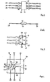
- the Hall generators are arranged with their broad sides on a flat carrier substrate at a distance from one another along a common line with the same orientation with respect to the line in each case close to the edges of two opposite sides of the carrier substrate that are free of connections. Since the Hall generators are no longer arranged with their broad sides one above the other but next to one another, the strength of the device is low. It is therefore possible to line up substantially more devices with their broad sides and to arrange them along the surface of the body to be tested. The area projected onto the surface of the test specimen of the Hall generators arranged one above the other with the narrow sides is smaller than in the case of two Hall generators arranged one above the other with the broad sides. This means that a finer assignment of the surface to the Hall generators is possible. It is therefore possible to localize errors more precisely. One of the two Hall generators can be arranged at a relatively short distance from the surface of the body to be tested. This increases the sensitivity. Therefore, relatively small defects in the test specimen can still be detected.
- the Hall generators are arranged in a housing with six connections, three of which are attached to opposite narrow sides, two control electrodes of the Hall generators being connected to one connection, while the other two control electrodes are connected to one connection each, and wherein two Hall electrodes, each of which have opposite polarities of the Hall voltages of the Hall generators, are connected to one another and connected to a common connection, while the other Hall electrodes are each connected to a connection.
- the Hall electrodes of the Hall generators are already connected to one another in a differential circuit on the carrier substrate. The type of connection with the connections allows both the difference in the Hall voltages and the individual Hall voltages to be tapped at the connections. It is also possible to supply only one control current to the control electrodes via the connections.
- connections connected to a control electrode must be connected in parallel.
- two separate control currents can also be fed in, which must then be related to a common potential at the control electrodes connected to one another.
- the control electrodes connected to one another in the housing are preferably connected to ground potential. With a minimum of connections to the housing, the Hall generators can thus be inserted in different circuit variants.
- the Hall generators expediently consist of gallium arsenide. Hall generators of this type generate high Hall voltages with relatively small dimensions.
- the housing is preferably made of plastic. The device can be manufactured inexpensively with a plastic housing.
- the center lines of the rectangular Hall generators are advantageous to arrange at a distance of about 0.55 mm from the nearest edge of the housing free of connections. It has been shown that such a distance can be achieved taking into account the conditions of the carrier substrate, the electrodes of the Hall generator, the connecting lines to the electrodes and the fastening between the carrier substrate and the plastic housing. Because of this small distance, the respective Hall generator can be attached with its narrow side very close to the surface of the body to be tested, which improves the sensitivity of the measurement.
- the housing preferably has a thickness of approximately 0.8 mm. Numerous housings adjoining one another with their broad sides can therefore be put together in groups, the individual housing on the surface of the body to be tested only corresponding to a small area. Structural disturbances, which are determined by a measuring probe consisting of the two Hall generators arranged in a housing, can therefore be located precisely on the surface.
- the distance between the centers of the two Hall generators is approximately 2.5 mm. With regard to the three connections of the housing arranged side by side in a row, this distance is sufficient for a space-saving construction of the probe.
- the housing 16 is made of plastic and has a flat cuboid shape.
- the connections 24 to 34 can consist of straight metal pins with a rectangular cross section.
- the width of these metal pins 24 to 34 is each about 0.6 mm, while the thickness is about 0.15 - 0.2 mm.
- the dimensions of the housing 16 in length and width are approximately 3 x 4 mm.
- the carrier substrate 18 is a flat plate.
- the Hall generators 12, 14 are arranged on the surface of the plate in a plane at a distance from one another along a common line 36, which is shown in broken lines in FIG. 3.
- the Hall generators 12, 14 are designed as rectangular gallium arsenide platelets which have the same angular position with respect to the line 36.
- the gallium arsenide platelets are each arranged with an edge 38 close to the edge 40 of the two narrow sides of the housing 16, which are not provided with the connections 24 to 34.
- the distance between the edges 40 and the center lines 42 running through the center of the gallium arsenide platelets parallel to the edges 40 is approximately 0.55 mm. There is a distance of approximately 2.55 mm between the two center lines 42.
- the height of the arrangement consisting of the carrier substrate 18 and the plastic attachment is 0.8 mm.
- the Hall generators 12, 14 each contain control electrodes 44, 46 and 48, 50.
- the control electrodes 44, 48 are connected to one another and connected together to the terminal 8.
- the control electrodes 46, 50 are connected to the connection 30 and 34, respectively.
- the Hall generators 12, 14 each contain Hall electrodes 52, 54, 56, 58.
- the two Hall electrodes 52, 56 are connected to one another and connected to the connection 26.
- the Hall electrodes 54, 58 are each connected to a connection 32 and 24, respectively.
- the connection between the Hall electrodes of the Hall generators 12, 14 is selected so that the Hall voltages have opposite polarities.
- each individual Hall voltage can also be tapped individually at the connections 28 and 32 or 28 and 24.
- connection 26 It is possible to supply a control current to the two Hall generators 12, 14 via the connection 26 and the connections 30, 34 to be connected to one another, which control current is divided between the two Hall generators 12, 14.
- a control current can also be supplied separately to the Hall generators 12 and 14 via the connections 30, 34. The tax flows then unite and flow together to connection 26, to which both control current generators with one pole each are to be connected. It is advisable to apply terminal 26 to ground potential.
- the broad sides of the Hall generators 12, 14 can be attached perpendicular to the surface element to be tested in each case.
- one of the Hall generators 12 and 14 can be arranged at a short distance from the surface of the test specimen. In this way, relatively small stray fluxes and thus small defects in the structure of the body to be tested are also recognized. Due to the small spatial extent of the narrow side of the respective Hall generator 12, 14 projected onto the surface of the test object, a more precise assignment of errors to the individual sections of the test object is possible.
- Numerous housings 14 can be arranged with their broad sides next to one another along a strip of the surface of the body to be tested. The body to be tested is then moved across the row of measuring probes. Movement along the row is not necessary to detect errors. The assignment of errors to the respective locations results from the geometrical position of the Hall probe that detects an error in relation to the body.
Landscapes
- Physics & Mathematics (AREA)
- General Physics & Mathematics (AREA)
- Condensed Matter Physics & Semiconductors (AREA)
- Chemical & Material Sciences (AREA)
- Analytical Chemistry (AREA)
- Electrochemistry (AREA)
- Health & Medical Sciences (AREA)
- Life Sciences & Earth Sciences (AREA)
- Chemical Kinetics & Catalysis (AREA)
- Biochemistry (AREA)
- General Health & Medical Sciences (AREA)
- Immunology (AREA)
- Pathology (AREA)
- Investigating Or Analyzing Materials By The Use Of Magnetic Means (AREA)
- Measuring Magnetic Variables (AREA)
- Hall/Mr Elements (AREA)
Applications Claiming Priority (2)
| Application Number | Priority Date | Filing Date | Title |
|---|---|---|---|
| DE19843435455 DE3435455A1 (de) | 1984-09-27 | 1984-09-27 | Vorrichtung mit zwei hallgeneratoren zur messung der gradienten magnetischer felder |
| DE3435455 | 1984-09-27 |
Publications (2)
| Publication Number | Publication Date |
|---|---|
| EP0180034A1 true EP0180034A1 (fr) | 1986-05-07 |
| EP0180034B1 EP0180034B1 (fr) | 1990-03-21 |
Family
ID=6246490
Family Applications (1)
| Application Number | Title | Priority Date | Filing Date |
|---|---|---|---|
| EP85112087A Expired - Lifetime EP0180034B1 (fr) | 1984-09-27 | 1985-09-24 | Dispositif avec deux générateurs de Hall pour mesurer le gradient de champs magnétiques |
Country Status (4)
| Country | Link |
|---|---|
| US (1) | US4692702A (fr) |
| EP (1) | EP0180034B1 (fr) |
| JP (1) | JPS61107153A (fr) |
| DE (2) | DE3435455A1 (fr) |
Families Citing this family (14)
| Publication number | Priority date | Publication date | Assignee | Title |
|---|---|---|---|---|
| US4859941A (en) * | 1987-03-18 | 1989-08-22 | Sprague Electric Company | Proximity selectro with integral magnet, pole-piece plate and pair of magnetic transducers |
| US4882512A (en) * | 1988-09-19 | 1989-11-21 | Honeywell, Inc. | Electromagnetic force sensor |
| US4935698A (en) * | 1989-03-03 | 1990-06-19 | Sprague Electric Company | Sensor having dual Hall IC, pole piece and magnet |
| JPH02150585U (fr) * | 1989-05-26 | 1990-12-26 | ||
| US4985953A (en) * | 1990-02-21 | 1991-01-22 | Louisville Bedding Co. | Fitted mattress cover |
| WO1991015778A1 (fr) * | 1990-04-02 | 1991-10-17 | Kim Kwee Ng | Compas a semi-conducteurs |
| US5241270A (en) * | 1990-04-02 | 1993-08-31 | Kim Kwee Ng | Electronic compass using hall-effect sensors |
| DE9011477U1 (de) * | 1990-08-07 | 1990-12-20 | Nukem GmbH, 63755 Alzenau | Anordnung zur zerstörungsfreien Werkstoffprüfung |
| DE9011478U1 (de) * | 1990-08-07 | 1990-12-20 | Nukem GmbH, 63755 Alzenau | Anordnung zur zerstörungsfreien Werkstoffprüfung |
| US5304926A (en) * | 1992-04-08 | 1994-04-19 | Honeywell Inc. | Geartooth position sensor with two hall effect elements |
| US6019086A (en) * | 1998-05-28 | 2000-02-01 | Cummins Engine Co. Inc. | Redundant sensor apparatus for determining engine speed and timing values |
| US6067824A (en) * | 1998-10-29 | 2000-05-30 | Optek Technology, Inc. | Automobile ignition security system using a differential magnetic comparator |
| US7126331B2 (en) * | 2002-07-29 | 2006-10-24 | The United States Of America As Represented By The Secretary Of The Navy | Integrated gradiometer |
| EP2624001B1 (fr) * | 2012-02-01 | 2015-01-07 | ams AG | Agencement de capteur et capteur Hall |
Citations (5)
| Publication number | Priority date | Publication date | Assignee | Title |
|---|---|---|---|---|
| DE1098584B (de) * | 1959-05-13 | 1961-02-02 | Siemens Ag | Hallspannungserzeuger-Anordnung |
| DE1194971B (de) * | 1963-04-25 | 1965-06-16 | Siemens Ag | Magnetfeld-Messsonde mit Hallgenerator |
| DE1257273B (de) * | 1956-03-26 | 1967-12-28 | Siemens Ag | Hallspannungserzeuger |
| US3710236A (en) * | 1970-11-30 | 1973-01-09 | Youngstown Sheet And Tube Co | Magnetic leakage field flaw detector utilizing partially overlapping hall probes |
| DE3305888A1 (de) * | 1983-02-19 | 1984-08-23 | Erich Dr.-Ing. 5300 Bonn Steingroever | Geraet mit sonde fuer die messung von magnetischen potentialen |
Family Cites Families (14)
| Publication number | Priority date | Publication date | Assignee | Title |
|---|---|---|---|---|
| US2088650A (en) * | 1934-04-16 | 1937-08-03 | Harrison S Hartley | Polishing and scrubbing device |
| US2988650A (en) * | 1953-11-11 | 1961-06-13 | Siemens Ag | Hall-effect control element with utilization circuit |
| GB868765A (en) * | 1957-07-16 | 1961-05-25 | Siemens Ag | Improvements in or relating to apparatus for the measurement of magnetic field gradients |
| US2987669A (en) * | 1959-01-19 | 1961-06-06 | Gulton Ind Inc | Hall effect electromechanical sensing device |
| US3139600A (en) * | 1960-12-12 | 1964-06-30 | Sylvania Electric Prod | Variable voltage generator |
| DE2025317A1 (de) * | 1969-05-26 | 1970-12-03 | Förster, Friedrich, Dr.phil., 7410 Reutlingen | Verfahren und Anordnung zum Prüfen der Innenseite eines nichtferromagnetischen Prüfteils |
| US3657686A (en) * | 1969-12-17 | 1972-04-18 | Denki Onkyo Co Ltd | Galvano-magnetro effect apparatus |
| DE2825214A1 (de) * | 1978-06-08 | 1979-12-13 | Otdel Fiz Nerazrusha Kontr | Magnetisches kontrollverfahren fuer die guetekennwerte von gegenstaenden und einrichtung zur durchfuehrung des verfahrens |
| JPS55125688A (en) * | 1979-03-23 | 1980-09-27 | Toshiba Corp | Hall effect device |
| NO802936L (no) * | 1979-10-08 | 1981-04-09 | Duraplug Elect Ltd | Elektrisk bryteranordning |
| US4395677A (en) * | 1981-02-13 | 1983-07-26 | Chrysler Corporation | Hall Effect tester for heated window grids |
| US4443716A (en) * | 1982-01-26 | 1984-04-17 | Sprague Electric Company | Symmetrical-hysteresis Hall switch |
| JPS597269A (ja) * | 1982-07-05 | 1984-01-14 | Fuji Electric Co Ltd | 電流検出器 |
| US4518918A (en) * | 1982-09-28 | 1985-05-21 | Sprague Electric Company | Ferromagnetic article detector with dual Hall-sensors |
-
1984
- 1984-09-27 DE DE19843435455 patent/DE3435455A1/de not_active Withdrawn
-
1985
- 1985-09-06 US US06/773,258 patent/US4692702A/en not_active Expired - Fee Related
- 1985-09-24 EP EP85112087A patent/EP0180034B1/fr not_active Expired - Lifetime
- 1985-09-24 DE DE8585112087T patent/DE3576735D1/de not_active Expired - Fee Related
- 1985-09-25 JP JP60210344A patent/JPS61107153A/ja active Pending
Patent Citations (5)
| Publication number | Priority date | Publication date | Assignee | Title |
|---|---|---|---|---|
| DE1257273B (de) * | 1956-03-26 | 1967-12-28 | Siemens Ag | Hallspannungserzeuger |
| DE1098584B (de) * | 1959-05-13 | 1961-02-02 | Siemens Ag | Hallspannungserzeuger-Anordnung |
| DE1194971B (de) * | 1963-04-25 | 1965-06-16 | Siemens Ag | Magnetfeld-Messsonde mit Hallgenerator |
| US3710236A (en) * | 1970-11-30 | 1973-01-09 | Youngstown Sheet And Tube Co | Magnetic leakage field flaw detector utilizing partially overlapping hall probes |
| DE3305888A1 (de) * | 1983-02-19 | 1984-08-23 | Erich Dr.-Ing. 5300 Bonn Steingroever | Geraet mit sonde fuer die messung von magnetischen potentialen |
Also Published As
| Publication number | Publication date |
|---|---|
| US4692702A (en) | 1987-09-08 |
| EP0180034B1 (fr) | 1990-03-21 |
| DE3576735D1 (de) | 1990-04-26 |
| JPS61107153A (ja) | 1986-05-26 |
| DE3435455A1 (de) | 1986-03-27 |
Similar Documents
| Publication | Publication Date | Title |
|---|---|---|
| EP0607595B1 (fr) | Capteur en puce | |
| EP0180034B1 (fr) | Dispositif avec deux générateurs de Hall pour mesurer le gradient de champs magnétiques | |
| DE2458398C2 (fr) | ||
| EP0707218A2 (fr) | Capteur en puce | |
| DE2509927C3 (de) | Wirbelstromprüf spulenanordnung | |
| DE2829784C2 (de) | Gerät zur Materialbearbeitung mittels eines durch ein Störmagnetfeld verlaufenden Ladungsträgerstrahles | |
| DE2725354C2 (de) | Prüfkopf zur induktiven Oberflächenprüfung von metallischen Werkstücken | |
| DE2935887C2 (fr) | ||
| DE1648450A1 (de) | Fehlerdetektor zur elektroinduktiven Materialpruefung | |
| EP0238524A1 (fr) | Agencement de transformateur de courant pour un compteur d'electricite statique. | |
| DE102019113296A1 (de) | Zweiachspositioniervorrichtung | |
| DE102019210301A1 (de) | Sensoranordnung zum Erfassen einer Auslenkung einer Drahtelektrode | |
| DE2743954A1 (de) | Verfahren zur messung des stroms einer fluessigkeit mittels eines induktiven stroemungsmessers | |
| DE3438658C1 (de) | Anordnung von Hallgeneratoren | |
| DE1194971B (de) | Magnetfeld-Messsonde mit Hallgenerator | |
| DE2232081A1 (de) | Verfahren zur feststellung von diskontinuitaeten in metallischen prueflingen | |
| DE3619423C2 (fr) | ||
| DE4308375C2 (de) | Störspannungskompensierte Halleffekt-Einrichtung | |
| EP0065579A1 (fr) | Sonde pour mesurer l'intensité et la direction des champs magnétiques faibles | |
| DE2717420A1 (de) | Kontaktstift | |
| DD255214A1 (de) | Verfahren zur beruehrungslosen messung von hochstroemen, insbesondere in elektroenergieanlagen | |
| DE976802C (de) | Einrichtung zum Messen der Magnetisierungsintensitaet von Proben aus magnetisierbaren Werkstoffen | |
| DE2302270C3 (de) | Magnetometer-Sonde und Sondenanordnungen aus dieser Sonde | |
| DE523530C (de) | Elektrisches Mutungsverfahren mit Gleichstrom nach der Sondenmethode | |
| DE734096C (de) | Anordnung zur Messung der Intensitaet magnetischer Gleichfelder, insbesondere des Erdfeldes |
Legal Events
| Date | Code | Title | Description |
|---|---|---|---|
| PUAI | Public reference made under article 153(3) epc to a published international application that has entered the european phase |
Free format text: ORIGINAL CODE: 0009012 |
|
| AK | Designated contracting states |
Kind code of ref document: A1 Designated state(s): DE FR GB IT |
|
| 17P | Request for examination filed |
Effective date: 19861022 |
|
| 17Q | First examination report despatched |
Effective date: 19880525 |
|
| GRAA | (expected) grant |
Free format text: ORIGINAL CODE: 0009210 |
|
| AK | Designated contracting states |
Kind code of ref document: B1 Designated state(s): DE FR GB IT |
|
| REF | Corresponds to: |
Ref document number: 3576735 Country of ref document: DE Date of ref document: 19900426 |
|
| ITF | It: translation for a ep patent filed | ||
| GBT | Gb: translation of ep patent filed (gb section 77(6)(a)/1977) | ||
| ET | Fr: translation filed | ||
| PLBE | No opposition filed within time limit |
Free format text: ORIGINAL CODE: 0009261 |
|
| STAA | Information on the status of an ep patent application or granted ep patent |
Free format text: STATUS: NO OPPOSITION FILED WITHIN TIME LIMIT |
|
| 26N | No opposition filed | ||
| PGFP | Annual fee paid to national office [announced via postgrant information from national office to epo] |
Ref country code: GB Payment date: 19920911 Year of fee payment: 8 |
|
| PGFP | Annual fee paid to national office [announced via postgrant information from national office to epo] |
Ref country code: DE Payment date: 19920923 Year of fee payment: 8 |
|
| PGFP | Annual fee paid to national office [announced via postgrant information from national office to epo] |
Ref country code: FR Payment date: 19920929 Year of fee payment: 8 |
|
| ITTA | It: last paid annual fee | ||
| PG25 | Lapsed in a contracting state [announced via postgrant information from national office to epo] |
Ref country code: GB Effective date: 19930924 |
|
| GBPC | Gb: european patent ceased through non-payment of renewal fee |
Effective date: 19930924 |
|
| PG25 | Lapsed in a contracting state [announced via postgrant information from national office to epo] |
Ref country code: FR Free format text: LAPSE BECAUSE OF NON-PAYMENT OF DUE FEES Effective date: 19940531 |
|
| PG25 | Lapsed in a contracting state [announced via postgrant information from national office to epo] |
Ref country code: DE Effective date: 19940601 |
|
| REG | Reference to a national code |
Ref country code: FR Ref legal event code: ST |