EP0180056A2 - Rückwandverdrahtung für elektrische Baugruppen - Google Patents
Rückwandverdrahtung für elektrische Baugruppen Download PDFInfo
- Publication number
- EP0180056A2 EP0180056A2 EP85112551A EP85112551A EP0180056A2 EP 0180056 A2 EP0180056 A2 EP 0180056A2 EP 85112551 A EP85112551 A EP 85112551A EP 85112551 A EP85112551 A EP 85112551A EP 0180056 A2 EP0180056 A2 EP 0180056A2
- Authority
- EP
- European Patent Office
- Prior art keywords
- centering
- contact
- backplane
- contact blades
- openings
- Prior art date
- Legal status (The legal status is an assumption and is not a legal conclusion. Google has not performed a legal analysis and makes no representation as to the accuracy of the status listed.)
- Granted
Links
Images
Classifications
-
- H—ELECTRICITY
- H05—ELECTRIC TECHNIQUES NOT OTHERWISE PROVIDED FOR
- H05K—PRINTED CIRCUITS; CASINGS OR CONSTRUCTIONAL DETAILS OF ELECTRIC APPARATUS; MANUFACTURE OF ASSEMBLAGES OF ELECTRICAL COMPONENTS
- H05K7/00—Constructional details common to different types of electric apparatus
- H05K7/14—Mounting supporting structure in casing or on frame or rack
- H05K7/1438—Back panels or connecting means therefor; Terminals; Coding means to avoid wrong insertion
- H05K7/1452—Mounting of connectors; Switching; Reinforcing of back panels
-
- H—ELECTRICITY
- H01—ELECTRIC ELEMENTS
- H01R—ELECTRICALLY-CONDUCTIVE CONNECTIONS; STRUCTURAL ASSOCIATIONS OF A PLURALITY OF MUTUALLY-INSULATED ELECTRICAL CONNECTING ELEMENTS; COUPLING DEVICES; CURRENT COLLECTORS
- H01R13/00—Details of coupling devices of the kinds covered by groups H01R12/70 or H01R24/00 - H01R33/00
- H01R13/40—Securing contact members in or to a base or case; Insulating of contact members
- H01R13/42—Securing in a demountable manner
- H01R13/422—Securing in resilient one-piece base or case, e.g. by friction; One-piece base or case formed with resilient locking means
Definitions
- the invention relates to a backplane wiring for electrical assemblies, consisting of a backplane with inserted contact blades and pluggable thereon as a one-sided open right-angled housing formed centering strips for receiving female connectors that are firmly connected to electrical assemblies, wherein the centering strips in the floor have openings for the contact blades.
- Centering strips of this type which can be plugged onto the backplane, for receiving corresponding female connectors must meet several requirements. They should be easily attachable, but should hold well when attached. If too much pressure has to be exerted when plugging on the centering strips, it can happen that the contact blades are pressed out of the backplane, since these have only a limited holding force. It should also be possible to replace individual contact blades without damaging the centering strips when centering strips are attached.
- the object of the present invention is therefore to provide a backplane wiring comprising a backplane and centering strips, in which the centering strips can be plugged on without great effort and hold well on the backplane when plugged in.
- the contact knife is held in the centering strip by means of the resilient web in the bottom of the centering strip and by means of the spherical pock on the contact knife.
- This provides definable holding forces. Due to the resilience of the resilient web, the centering bar can be plugged onto pre-assembled backplane boards without great effort. Because the web yields elastically, the contact blades can be replaced without sacrificing the holding function.
- An expedient embodiment of the rear wall wiring according to the invention is characterized in that all or part of the additional openings in the bottom of the centering strips are narrowed by shoulders. This prevents incorrect placement of the centering bar on the contact blades of the backplane when mounting the centering bar.
- Another expedient embodiment of the rear wall wiring according to the invention is characterized in that the through openings for the contact knives have a recess on one long side, so that there is the possibility that contact knives with elastic press-in zones can also be used.
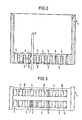
- Fig. 2 shows a cross section through a centering bar according to the present invention, which is equipped with contact blades 2 according to the invention.
- the contact blades 2 penetrate through the through openings 4, as can be seen from FIG. 3.
- an additional opening 5 is provided, as a result of which a resilient web 6 is formed next to each passage opening 4.
- the pock 7 of the contact knife 2 presses against this web. This provides precisely definable holding forces for the contact blades in the centering strips 1.
- the contact blades 2 have a lateral play in the passage openings 4 in order to compensate for tolerances in the longitudinal direction create. Characterized in that the resilient web 6 yields when the centering strip 1 is plugged onto the contact knife 2, the centering strip 1 can easily be plugged onto the contact knife 2 in the rear wall wiring according to the invention.
- all or part of the additional openings 5 can be provided with lugs 9 at their lower ends.
- the spring properties of the web 6 are not affected by these approaches 9.
- the passage opening 4 for the contact blades 2 additionally have cutouts 8. These are only intended for the case that contact blades with elastic press-in zones are used.
Landscapes
- Engineering & Computer Science (AREA)
- Microelectronics & Electronic Packaging (AREA)
- Installation Of Indoor Wiring (AREA)
- Mounting Of Printed Circuit Boards And The Like (AREA)
- Coupling Device And Connection With Printed Circuit (AREA)
Abstract
Description
- Die Erfindung betrifft eine Rückwandverdrahtung für elektrische Baugruppen, bestehend aus einer Rückwandleiterplatte mit eingesetzten Kontaktmessern und darauf aufsteckbaren als einseitig offene rechtwinklige Gehäuse ausgebildeten Zentrierleisten zur Aufnahme von Federleisten, die mit elektrischen Baugruppen fest verbunden sind, wobei die Zentrierleisten im Boden Durchtrittsöffnungen für die Kontaktmesser aufweisen.
- Derartige auf die Rückwandleiterplatte aufsteckbare Zentrierleisten zur Aufnahme entsprechender Federleisten müssen mehrere Forderungen erfüllen. Sie sollen leicht aufsteckbar sein, im aufgesteckten Zustand aber gut halten. Muß beim Aufstecken der Zentrierleisten ein zu großer Druck ausgeübt werden, so kann es passieren, daß die Kontaktmesser aus der Rückwandleiterplatte herausgedrückt werden, da diese nur eine begrenzte Haltekraft aufweisen. Auch soll bei aufgesteckten Zentrierleisten der Austausch einzelner Kontaktmesser ohne Beschädigung der Zentrierleisten möglich sein.
- Aufgabe der vorliegenden Erfindung ist es daher, eine Rückwandverdrahtung aus Rückwandleiterplatte und Zentrierleisten anzugeben, bei der die Zentrierleisten ohne großen Kraftaufwand aufgesteckt werden können und im aufgesteckten Zustand gut auf der Rückwandleiterplatte halten.
- Diese Aufgabe wird für eine Rückwandverdrahtung der eingangs genannten Art erfindungsgemäß dadurch gelöst, daß neben jeder Durchtrittsöffnung für ein Kontaktmesser eine zusätzliche Öffnung vorgesehen ist, welche durch einen Steg von der Durchtrittsöffnung für das Kontaktmesser getrennt ist, und daß das Kontaktmesser auf einer Seite eine kalottenförmige Pocke aufweist, die nach dem Aufstecken der Zentrierleisten gegen den Steg drückt.
- Bei der erfindungsgemäßen Rückwandverdrahtung erfolgt die Halterung des Kontaktmessers in der Zentrierleiste mittels des federnden Steges im Boden der Zentrierleiste sowie mittels der kalottenförmigen Pocke auf den Kontaktmesser. Dadurch liegen definierbare Haltekräfte vor. Durch die Nachgiebigkeit des federnden Steges läßt sich die Zentrierleiste auf vorbestückte Rückwandleiterplatten ohne großen Kraftaufwand aufstecken. Dadurch, daß der Steg elastisch nachgibt, können die Kontaktmesser ohne Einbuße der Haltefunktion ausgetauscht werden.
- Eine zweckmäßige Ausgestaltung der erfindungsgemäßen Rtickwandverdrahtung ist dadurch gekennzeichnet, daß alle oder ein Teil der zusätzlichen Öffnungen im Boden der Zentrierleisten durch Ansätze eingeengt sind. Dadurch wird beim Montieren der Zentrierleiste ein falsches Aufsetzen der Zentrierleiste auf die Kontaktmesser der Rückwandleiterplatte verhindert.
- Eine weitere zweckmäßige Ausgestaltung der erfindungsgemäßen Rückwandverdrahtung ist dadurch gekennzeichnet, daß die Durchtrittsöffnungen für die Kontaktmesser an einer Längsseite eine Aussparung aufweisen, wodurch die Möglichkeit besteht, daß auch Kontaktmesser mit elastischen Einpresszonen verwendet werden können.
- Im folgenden wird die Erfindung anhand eines in der Zeichnung dargestellten Ausführungsbeispieles näher erläutert.
- Es zeigen
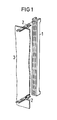
- Fig. 1 ein Teil einer Rückwandleiterplatte mit Kontaktmessern sowie eine Zentrierleiste,
- Fig. 2 einen Querschnitt der erfindungsgemäßen Zentrierleiste mit einem eingeschobenen Kontaktmesser, und
- Fig. 3 eine teilweise Draufsicht auf eine Zentrierleiste gemäß der vorliegenden Erfindung.
- Fig. 1 zeigt zum besseren Verständnis den prinzipiellen Aufbau einer Rückwandverdrahtung, bei der eine Zentrierleiste 1 auf eine mit Kontaktmessern zwei versehene Rückwandleiterplatte 3 aufgesteckt wird.
- Fig. 2 zeigt einen Querschnitt durch eine Zentrierleiste gemäß der vorliegenden Erfindung, die mit erfindungsgemäßen Kontaktmessern 2 bestückt ist. In der Darstellung wurde nur ein Kontaktmesser 2 mit einer kalottenförmigen Pocke 7 eingezeichnet. Beim Aufsetzen der Zentrierleiste 1 auf die Rückwandleiterplatte 3 dringen die Kontaktmesser 2 durch die Durchtrittsöffnungen 4 , wie sich aus der Fig. 3 entnehmen läßt. Neben jeder Durchtrittsöffnung 4 in der Zentrierleiste 1 ist eine zusätzliche Öffnung 5 vorgesehen, wodurch neben jeder Durchtrittsöffnung 4 ein federnder Steg 6 entsteht. Im aufgesteckten Zustand der Zentrierleiste 1 drückt die Pocke 7 des Kontaktmessers 2 gegen diesen Steg. Dadurch liegen genau definierbare Haltekräfte für die Kontaktmesser in den Zentrierleisten 1 vor.
- Wie sich der Fig. 3 entnehmen läßt haben die Kontaktmesser 2 in den Durchtrittsöffnungen 4 ein seitliches Spiel, um einen Toleranzausgleich in Längsrichtung zu schaffen. Dadurch, daß der federnde Steg 6 beim Aufstecken der Zentrierleiste 1 auf die Kontaktmesser 2 nachgibt, läßt sich bei der erfindungsgemäßen Rückwandverdrahtung die Zentrierleiste 1 leicht auf die Kontaktmesser 2 aufstecken.
- Um ein falsches Aufstecken zu vermeiden, d.h., um zu vermeiden daß die Kontaktmesser 2 versehentlich in die zusätzlichen Öffnungen 5 eindringen, können alle oder ein Teil der zusätzlichen öffnungen 5 an ihren unteren Enden mit Ansätzen 9 versehen werden. Durch diese Ansätze 9 werden die Federeigenschaften des Steges 6 nicht berührt.
- Die Durchtrittsöffnung 4 für die Kontaktmesser 2 weisen zusätzlich noch Aussparungen 8 auf. Diese sind lediglich für den Fall vorgesehen, daß Kontaktmesser mit elastischen Einpreßzonen Verwendung finden.
- 3 Patentansprüche
- 3 Figuren
Claims (3)
Applications Claiming Priority (2)
| Application Number | Priority Date | Filing Date | Title |
|---|---|---|---|
| DE3439886 | 1984-10-31 | ||
| DE3439886 | 1984-10-31 |
Publications (3)
| Publication Number | Publication Date |
|---|---|
| EP0180056A2 true EP0180056A2 (de) | 1986-05-07 |
| EP0180056A3 EP0180056A3 (en) | 1988-01-07 |
| EP0180056B1 EP0180056B1 (de) | 1991-01-09 |
Family
ID=6249204
Family Applications (1)
| Application Number | Title | Priority Date | Filing Date |
|---|---|---|---|
| EP85112551A Expired - Lifetime EP0180056B1 (de) | 1984-10-31 | 1985-10-03 | Rückwandverdrahtung für elektrische Baugruppen |
Country Status (4)
| Country | Link |
|---|---|
| US (1) | US4826453A (de) |
| EP (1) | EP0180056B1 (de) |
| JP (1) | JPS61110981A (de) |
| DE (1) | DE3581265D1 (de) |
Cited By (5)
| Publication number | Priority date | Publication date | Assignee | Title |
|---|---|---|---|---|
| EP0275066A1 (de) * | 1987-01-13 | 1988-07-20 | Siemens Aktiengesellschaft | Anschlussfeld mit rastermässig in einer Isolierstoffplatte befestigten Anschlusspfosten und einer an den Pfosten fixierbaren Lochplatte |
| EP0275067A1 (de) * | 1987-01-13 | 1988-07-20 | Siemens Aktiengesellschaft | Zum Aufstecken auf eine Gruppe von Pfosten eines Anschlussfeldes vorgesehene Vorrichtung |
| GB2204740A (en) * | 1987-05-01 | 1988-11-16 | Otehall Limited | Housings for electrical components |
| EP0397057A1 (de) * | 1989-05-12 | 1990-11-14 | Siemens Aktiengesellschaft | Anordnung zur mechanischen und elektrischen Verbindung einer Ergänzungsleiterplatte an einer Grundleiterplatte |
| EP0488298A3 (en) * | 1990-11-30 | 1993-01-20 | Amp Incorporated | Connector with equal lateral force contact spacer plate |
Families Citing this family (5)
| Publication number | Priority date | Publication date | Assignee | Title |
|---|---|---|---|---|
| US5102356A (en) * | 1991-05-24 | 1992-04-07 | Amp Incorporated | Electrical connector having board retention means |
| JP2645629B2 (ja) * | 1992-07-08 | 1997-08-25 | 矢崎総業株式会社 | 回路基板用コネクタ |
| US5263882A (en) * | 1992-11-02 | 1993-11-23 | Molex Incorporated | Electrical connector with improved terminal retention means |
| US5571033A (en) * | 1995-02-21 | 1996-11-05 | The Whitaker Corporation | Electrical connector having press-fit contacts for circuit board mounting |
| US6113438A (en) * | 1999-06-16 | 2000-09-05 | Molex Incorporated | Electrical connector and method of assembling same |
Family Cites Families (16)
| Publication number | Priority date | Publication date | Assignee | Title |
|---|---|---|---|---|
| US3139492A (en) * | 1961-01-11 | 1964-06-30 | Jr Albert G Cage | Repositionable connector plug with position eliminator means |
| GB1029090A (en) * | 1963-12-27 | 1966-05-11 | Lucas Industries Ltd | Plug and socket connectors |
| US3673548A (en) * | 1970-10-19 | 1972-06-27 | Itt | Printed circuit board connector |
| DE2119987B2 (de) * | 1971-04-23 | 1979-05-31 | Bunker Ramo Corp., Oak Brook, Ill. (V.St.A.) | Kontaktleiste |
| NL154368B (nl) * | 1971-05-28 | 1977-08-15 | Amp Inc | Elektrische verbindingsinrichting met een plaatvormig contactorgaan dat losneembaar, veerkrachtig in een doorgaande opening wordt vastgehouden. |
| FR2139386A7 (de) * | 1972-05-09 | 1973-01-05 | Siemens Ag | |
| US4056300A (en) * | 1973-02-20 | 1977-11-01 | Gte Sylvania Incorporated | Terminal connector with stress relief |
| DE7422768U (de) * | 1974-07-04 | 1974-11-14 | Kontaktron Gmbh | Lötfreie, elektrische Verbindung |
| US3950060A (en) * | 1974-10-29 | 1976-04-13 | Molex Incorporated | Connector assembly |
| US4035047A (en) * | 1974-12-19 | 1977-07-12 | Elfab Corporation | Electrical connector |
| JPS5248308A (en) * | 1975-10-15 | 1977-04-18 | Kawai Musical Instr Mfg Co Ltd | Controller for effecting device of electronic instrument |
| JPS6240684Y2 (de) * | 1978-08-05 | 1987-10-17 | ||
| US4472012A (en) * | 1981-03-04 | 1984-09-18 | Molex Incorporated | Modularized universal pin and sleeve electrical connector |
| JPS6079681A (ja) * | 1983-09-28 | 1985-05-07 | モレツクス・インコ−ポレ−テツド | ヒンジ付電気コネクタ− |
| US4544220A (en) * | 1983-12-28 | 1985-10-01 | Amp Incorporated | Connector having means for positively seating contacts |
| US4565416A (en) * | 1984-04-11 | 1986-01-21 | Amp Incorporated | Latching means and locking means for retaining terminals in a connector |
-
1985
- 1985-10-03 EP EP85112551A patent/EP0180056B1/de not_active Expired - Lifetime
- 1985-10-03 DE DE8585112551T patent/DE3581265D1/de not_active Expired - Lifetime
- 1985-10-31 JP JP60243049A patent/JPS61110981A/ja active Pending
-
1987
- 1987-04-09 US US07/036,292 patent/US4826453A/en not_active Expired - Lifetime
Cited By (6)
| Publication number | Priority date | Publication date | Assignee | Title |
|---|---|---|---|---|
| EP0275066A1 (de) * | 1987-01-13 | 1988-07-20 | Siemens Aktiengesellschaft | Anschlussfeld mit rastermässig in einer Isolierstoffplatte befestigten Anschlusspfosten und einer an den Pfosten fixierbaren Lochplatte |
| EP0275067A1 (de) * | 1987-01-13 | 1988-07-20 | Siemens Aktiengesellschaft | Zum Aufstecken auf eine Gruppe von Pfosten eines Anschlussfeldes vorgesehene Vorrichtung |
| GB2204740A (en) * | 1987-05-01 | 1988-11-16 | Otehall Limited | Housings for electrical components |
| GB2204740B (en) * | 1987-05-01 | 1990-11-14 | Otehall Limited | Electrical components |
| EP0397057A1 (de) * | 1989-05-12 | 1990-11-14 | Siemens Aktiengesellschaft | Anordnung zur mechanischen und elektrischen Verbindung einer Ergänzungsleiterplatte an einer Grundleiterplatte |
| EP0488298A3 (en) * | 1990-11-30 | 1993-01-20 | Amp Incorporated | Connector with equal lateral force contact spacer plate |
Also Published As
| Publication number | Publication date |
|---|---|
| US4826453A (en) | 1989-05-02 |
| EP0180056B1 (de) | 1991-01-09 |
| DE3581265D1 (de) | 1991-02-14 |
| JPS61110981A (ja) | 1986-05-29 |
| EP0180056A3 (en) | 1988-01-07 |
Similar Documents
| Publication | Publication Date | Title |
|---|---|---|
| DE4241876C2 (de) | Einschub-/Entnahmevorrichtung für Schaltungsplatinen | |
| DE1914489B2 (de) | Verfahren zur Befestigung eines Steckkontaktes an einer gedruckten Schaltplatte | |
| DE2941029A1 (de) | Zum einpressverbinden mit einem elektrischen leiter vorgesehenen elektrischen anschlussteil, verfahren zum verbinden eines anschlussteils mit einem elektrischen leiter sowie verbinder mit einer mehrzahl elektrischer anschlussteile | |
| EP0937317B1 (de) | Baugruppenträger für leiterplatten mit mittelquerschienen | |
| EP0180056B1 (de) | Rückwandverdrahtung für elektrische Baugruppen | |
| DE2453843A1 (de) | Steckverbinder-anordnung | |
| EP0182070B1 (de) | Elektrische Steckverbinderleiste | |
| DE1765989C3 (de) | Steckverbinder für die Aufnahme einer mit Kontaktflächen versehenen Druckschaltungskarte | |
| DE2812332C3 (de) | Vielfachsteckverbindung für Karten mit gedruckter Schaltung | |
| DE29911398U1 (de) | Elektrische Verbindungseinrichtung mit einer Schaltungsplatte | |
| DE2840890A1 (de) | Mehrlagenverbindungsplatte mit mindestens einer loecher aufweisenden metallplatte und mit mindestens einer durchplattierte loecher ausweisenden gedruckten leiterplatte | |
| EP0239785A1 (de) | Zentrierleiste zum Aufstecken auf eine mit Kontaktmessern versehene Rückwandleiterplatte | |
| DE19830878B4 (de) | Elektrische Verbindungsanordnung zwischen zwei elektrischen Bauelementen für ein elektrisches Bauteil | |
| EP0284855A1 (de) | Kontaktiervorrichtung und Verfahren zum Anschluss einer Leiterfolie | |
| DE1139894B (de) | Einschubrahmen zur Aufnahme mehrerer Schaltungsplatten fuer Fernmeldeanlagen, insbesondere Fernsprechvermittlungsanlagen | |
| DE2745507C2 (de) | Steckplatte für den Aufbau elektronischer Schaltungen zu Lernzwecken | |
| DE2613704C2 (de) | Elektrische Steckvorrichtung | |
| CH607542A5 (en) | Printed circuit board mechanical coding system | |
| DE3412700A1 (de) | Frontsteckverbinder | |
| DE8905361U1 (de) | Codiervorrichtung für auf eine Rückwandverdrahtung aufsteckbare elektrische Baugruppe | |
| DE8431973U1 (de) | Rückwandverdrahtung für elektrische Baugruppen | |
| EP0394753B1 (de) | Codiervorrichtung für auf eine Rückwandverdrahtung aufsteckbare elektrische Baugruppen | |
| DE2811204A1 (de) | Vorrichtung zum elektrischen anschluss an stromkreise einer druckschaltungskarte im bereich der vorderen, freien kante der karte | |
| DE29610780U1 (de) | Federleiste für Steckverbindungen zwischen einer Baugruppenleiterplatte und einer Rückwandverdrahtungsplatte | |
| EP4633299A1 (de) | Reiheneinbaugerät und verfahren zur herstellung eines reiheneinbaugeräts |
Legal Events
| Date | Code | Title | Description |
|---|---|---|---|
| PUAI | Public reference made under article 153(3) epc to a published international application that has entered the european phase |
Free format text: ORIGINAL CODE: 0009012 |
|
| AK | Designated contracting states |
Kind code of ref document: A2 Designated state(s): CH DE FR GB IT LI SE |
|
| PUAL | Search report despatched |
Free format text: ORIGINAL CODE: 0009013 |
|
| AK | Designated contracting states |
Kind code of ref document: A3 Designated state(s): CH DE FR GB IT LI SE |
|
| 17P | Request for examination filed |
Effective date: 19880627 |
|
| 17Q | First examination report despatched |
Effective date: 19900201 |
|
| GRAA | (expected) grant |
Free format text: ORIGINAL CODE: 0009210 |
|
| AK | Designated contracting states |
Kind code of ref document: B1 Designated state(s): CH DE FR GB IT LI SE |
|
| REF | Corresponds to: |
Ref document number: 3581265 Country of ref document: DE Date of ref document: 19910214 |
|
| ET | Fr: translation filed | ||
| ITF | It: translation for a ep patent filed | ||
| GBT | Gb: translation of ep patent filed (gb section 77(6)(a)/1977) | ||
| PLBE | No opposition filed within time limit |
Free format text: ORIGINAL CODE: 0009261 |
|
| STAA | Information on the status of an ep patent application or granted ep patent |
Free format text: STATUS: NO OPPOSITION FILED WITHIN TIME LIMIT |
|
| 26N | No opposition filed | ||
| EAL | Se: european patent in force in sweden |
Ref document number: 85112551.8 |
|
| REG | Reference to a national code |
Ref country code: CH Ref legal event code: PUE Owner name: SIEMENS AKTIENGESELLSCHAFT BERLIN UND MUENCHEN -DA Ref country code: CH Ref legal event code: NV Representative=s name: RIEDERER HASLER & PARTNER PATENTANWAELTE AG |
|
| REG | Reference to a national code |
Ref country code: GB Ref legal event code: 732E |
|
| REG | Reference to a national code |
Ref country code: GB Ref legal event code: IF02 |
|
| PGFP | Annual fee paid to national office [announced via postgrant information from national office to epo] |
Ref country code: GB Payment date: 20040915 Year of fee payment: 20 |
|
| PGFP | Annual fee paid to national office [announced via postgrant information from national office to epo] |
Ref country code: FR Payment date: 20041004 Year of fee payment: 20 |
|
| PGFP | Annual fee paid to national office [announced via postgrant information from national office to epo] |
Ref country code: SE Payment date: 20041005 Year of fee payment: 20 |
|
| PGFP | Annual fee paid to national office [announced via postgrant information from national office to epo] |
Ref country code: DE Payment date: 20041029 Year of fee payment: 20 |
|
| PGFP | Annual fee paid to national office [announced via postgrant information from national office to epo] |
Ref country code: CH Payment date: 20050107 Year of fee payment: 20 |
|
| PG25 | Lapsed in a contracting state [announced via postgrant information from national office to epo] |
Ref country code: GB Free format text: LAPSE BECAUSE OF EXPIRATION OF PROTECTION Effective date: 20051002 |
|
| REG | Reference to a national code |
Ref country code: GB Ref legal event code: PE20 |
|
| REG | Reference to a national code |
Ref country code: CH Ref legal event code: PL |
|
| EUG | Se: european patent has lapsed |