EP0180061A2 - Joint d'étanchéité pour lubrifiant pour des patins de chenille - Google Patents
Joint d'étanchéité pour lubrifiant pour des patins de chenille Download PDFInfo
- Publication number
- EP0180061A2 EP0180061A2 EP85112615A EP85112615A EP0180061A2 EP 0180061 A2 EP0180061 A2 EP 0180061A2 EP 85112615 A EP85112615 A EP 85112615A EP 85112615 A EP85112615 A EP 85112615A EP 0180061 A2 EP0180061 A2 EP 0180061A2
- Authority
- EP
- European Patent Office
- Prior art keywords
- radial
- link
- wall
- end wall
- bushing
- Prior art date
- Legal status (The legal status is an assumption and is not a legal conclusion. Google has not performed a legal analysis and makes no representation as to the accuracy of the status listed.)
- Ceased
Links
Images

Classifications
-
- B—PERFORMING OPERATIONS; TRANSPORTING
- B62—LAND VEHICLES FOR TRAVELLING OTHERWISE THAN ON RAILS
- B62D—MOTOR VEHICLES; TRAILERS
- B62D55/00—Endless track vehicles
- B62D55/08—Endless track units; Parts thereof
- B62D55/088—Endless track units; Parts thereof with means to exclude or remove foreign matter, e.g. sealing means, self-cleaning track links or sprockets, deflector plates or scrapers
- B62D55/0887—Track-articulation sealings against dust, water, mud or the like
-
- F—MECHANICAL ENGINEERING; LIGHTING; HEATING; WEAPONS; BLASTING
- F16—ENGINEERING ELEMENTS AND UNITS; GENERAL MEASURES FOR PRODUCING AND MAINTAINING EFFECTIVE FUNCTIONING OF MACHINES OR INSTALLATIONS; THERMAL INSULATION IN GENERAL
- F16C—SHAFTS; FLEXIBLE SHAFTS; ELEMENTS OR CRANKSHAFT MECHANISMS; ROTARY BODIES OTHER THAN GEARING ELEMENTS; BEARINGS
- F16C11/00—Pivots; Pivotal connections
- F16C11/04—Pivotal connections
- F16C11/045—Pivotal connections with at least a pair of arms pivoting relatively to at least one other arm, all arms being mounted on one pin
-
- F—MECHANICAL ENGINEERING; LIGHTING; HEATING; WEAPONS; BLASTING
- F16—ENGINEERING ELEMENTS AND UNITS; GENERAL MEASURES FOR PRODUCING AND MAINTAINING EFFECTIVE FUNCTIONING OF MACHINES OR INSTALLATIONS; THERMAL INSULATION IN GENERAL
- F16G—BELTS, CABLES, OR ROPES, PREDOMINANTLY USED FOR DRIVING PURPOSES; CHAINS; FITTINGS PREDOMINANTLY USED THEREFOR
- F16G13/00—Chains
- F16G13/02—Driving-chains
- F16G13/06—Driving-chains with links connected by parallel driving-pins with or without rollers so called open links
-
- F—MECHANICAL ENGINEERING; LIGHTING; HEATING; WEAPONS; BLASTING
- F16—ENGINEERING ELEMENTS AND UNITS; GENERAL MEASURES FOR PRODUCING AND MAINTAINING EFFECTIVE FUNCTIONING OF MACHINES OR INSTALLATIONS; THERMAL INSULATION IN GENERAL
- F16J—PISTONS; CYLINDERS; SEALINGS
- F16J15/00—Sealings
- F16J15/16—Sealings between relatively-moving surfaces
- F16J15/32—Sealings between relatively-moving surfaces with elastic sealings, e.g. O-rings
-
- F—MECHANICAL ENGINEERING; LIGHTING; HEATING; WEAPONS; BLASTING
- F16—ENGINEERING ELEMENTS AND UNITS; GENERAL MEASURES FOR PRODUCING AND MAINTAINING EFFECTIVE FUNCTIONING OF MACHINES OR INSTALLATIONS; THERMAL INSULATION IN GENERAL
- F16J—PISTONS; CYLINDERS; SEALINGS
- F16J15/00—Sealings
- F16J15/16—Sealings between relatively-moving surfaces
- F16J15/34—Sealings between relatively-moving surfaces with slip-ring pressed against a more or less radial face on one member
- F16J15/3436—Pressing means
- F16J15/3456—Pressing means without external means for pressing the ring against the face, e.g. slip-ring with a resilient lip
-
- F—MECHANICAL ENGINEERING; LIGHTING; HEATING; WEAPONS; BLASTING
- F16—ENGINEERING ELEMENTS AND UNITS; GENERAL MEASURES FOR PRODUCING AND MAINTAINING EFFECTIVE FUNCTIONING OF MACHINES OR INSTALLATIONS; THERMAL INSULATION IN GENERAL
- F16C—SHAFTS; FLEXIBLE SHAFTS; ELEMENTS OR CRANKSHAFT MECHANISMS; ROTARY BODIES OTHER THAN GEARING ELEMENTS; BEARINGS
- F16C33/00—Parts of bearings; Special methods for making bearings or parts thereof
- F16C33/72—Sealings
- F16C33/74—Sealings of sliding-contact bearings
Definitions
- This invention relates to a track linkage assembly, particularly to the portion thereof providing lubricant sealing in installations that lie on each side of a continuous track at each place where the successive links are connected together.
- the invention relates to a replacement lubricant seal at this location and to the installation which includes this replacement seal.
- Tracks such as as. those on caterpillar-type tractors comprise a large number of individual links joined to each other.
- Each link is provided at each end with structure that enables it to be joined to the succeeding link.
- the two ends of each link are different from each other to provide a series of such linkages.
- the links are arranged in pairs on opposite sides of the track.
- Heavy oil or, perhaps grease in some structures is used to provide lubrication at the places where pins cross transversely between a pair of link ends and also join each pair of links to the succeeding pair of links, for at that linkage, the adjacent links can rotate somewhat relative to each other.
- the rotation is limited to considerably less than one hundred eighty degrees but does involve a certain amount of rotary reciprocation and wear of the bushing against the drive sprocket of the track.
- each transverse pin Adjacent each end of each transverse pin is a lubricant sealing member. It lies between a first link end and a bushing that, in effect, is part of a second link end. The rotary seal is between the bushing and the first link end. There is also a static seal against the first link end and the pin, which is tightly press-fitted to the first link end.
- the sealing member provided by the original equipment manufacturer may be part of an assembly that includes a two-element sealing member and a spacer ring. In some cases a one-element sealing member may be used, and the spacer ring may in some instances comprise part of a unitary sealing member.
- a portion of the sealing member provides static seals with the circumference of the pin and with the first link end, for the first link end and the pin, being connected together by a press-fit arrangement, comprise, for operational purposes, a single piece.
- the first link end provides a recess in which the sealing member or assembly are seated.
- the second link end and its accompanying bushing also being fitted together by a press fit, also act as a unit; the bushing provides a radial face against which a lip of the sealing member abuts to provide the rotary seal for retaining the lubricant inside the overall assembly.
- the sealing member has simultaneously been worn out and required replacement. More significantly, it has also worn the bushing so that there there is an annular groove in the end face of the bushing. This groove tends to frustrate reinstallation. If a new seal arrangement of the original type is put in, the lubricant will immediately begin leaking from the linkage, because the new seal will not make firm contact with the face of the bushing, due to the annular groove, which is of substantial depth. Machining off of the faces of the bushings is not practical, for that would worsen the situation.
- One object of the present invention is to provide for improved repair by a combination which includes a type of lubricant sealing member which is markedly different from that originally supplied.
- This different type of lubricant sealing member has a lip which runs on a different portion of the face, spaced away from the annular groove that has been worn into the face by the original sealing member.
- This new type of sealing member is suitable for use over a period even longer than the life of the original sealing member. Moreover, if the new sealing member itself wears, it can easily be replaced.
- Another object of the invention is to make possible reworking of the worn installation by mere inversion of the bushings and replacement of the seals, so that it will not be necessary to replace each bushing during the repair work.
- Another object of the invention is to provide for relatively inexpensive repair requiring only inversion of the bushing and a new sealing member.
- the track linkage assembly of this invention which provides lubricant sealing, is installed on each side of a continuous track at each place where successive links are connected.
- the invention includes a novel replacement seal, which takes the place of an original-equipment seal and spacer, and preferably comprises only a single elastomeric member, although it may have a spring, such as a finger spring or a spring steel insert to improve longevity but increasing the cost.
- first link end on each side of the track, each having a cylindrical opening therethrough, and an annular recess extending in from the end facing toward the opposite first link end.
- the recess ends in a radial face that extends out from the cylindrical opening to a larger-diameter cylindrical wall concentric with the cylindrical opening.
- the recess is provided in order to house and retain the sealing member or members; its cylindrical wall terminates at a radial end wall which extends out further radially, and is the end wall of the first link end.
- a cylindrical tubular pin is firmly press-fitted at each end into the cylindrical opening of one first link end; it is then coaxial with the inner cylindrical wall of the recess. This pin extends axially between the radial end walls of the pair of first link ends.
- each radial end wall Facing each radial end wall is a second link end, on a different link, having its own radial end wall facing the radial end wall of the adjacent first link end and spaced from it enough to provide clearance during relative rotation.
- Each second link end has an inner cylindrical wall, preferably in line with the inner cylindrical walls of the first link ends.
- An annular bushing with a cylindrical outer periphery is press-fitted at each end into the inner cylindrical wall of a second link end and joins these two second link ends together.
- An inner cylindrical periphery of this bushing surrounds the pin, there being a small amount of clearance between the pin and the bushing to enable relative rotary movement between the bushing and the pin and therefore between the first link ends and the second link ends.
- a generally radial wall joins its outer periphery to its inner periphery.
- This generally radial wall is truly radial when the bushing is new, but by the time when repair is needed it has been subjected to wear by its original equipment seal, which has to be replaced.
- the wear forms an annular groove in that radial wall near the outer periphery of the bushing.
- the original seal (and spacer, if used) are, in this invention, replaced by a single elastomeric annular lubricant sealing member.
- This sealing member is retained statically by friction in the cylindrical recess, a cylindrical outer periphery of the sealing member fitting tightly against the inner cylindrical wall of the first link end in a leak-tight fit.
- the sealing member of this invention has first and second end faces.
- the first end face has an outer radial portion in contact with the radial face at the inner end of the recess in the first link end. This outer radial portion may include an annular recess for accommodating elastomer movement.
- the second end face has an outer radial portion lying substantially in the same plane as the radial end wall of the first link end and has a recessed portion lying radially inwardly from the annular groove that has been worn into the bushing, the recessed portion terminating in a lip.
- the lip Before installation of the bushing, the lip has a circular edge lying beyond the plane of the radial end wall of the first link end; during installation, the lip edge is engaged by a radially inner portion of the generally radial wall of the bushing and is pushed toward and approximately to the plane of the radial end wall of the first link end. The lip edge and the bushing's radial wall provide the rotary sealing engagement.
- the lip also has an innermost portion, preferably curved, lying radially inwardly of the lip edge. Before installation of the bushing, this innermost portion is spaced away from the pin's outer periphery. On installation of the bushing, this portion is swung inwardly by the force of the, lip edge and is forced firmly into contact with the pin to form a static seal therewith.
- the seal, the first link end, and the pin constitute one unit for limited rotary movement relative to the second link end and the bushing as another unit.
- the lip edge and the outer radial portion of the sealing member are in rotary sealing engagement with the bushing's generally radial wall.
- the sealing member is made of carboxylated nitrile elastomer or some material with similar properties.
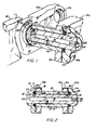
- Figs. 1 and 2 can be seen portions of a track linkage assembly for a caterpillar type of tractor.
- a track linkage assembly for a caterpillar type of tractor.
- Each link 10 or 10a is made with one portion, herein called a first link end 11 or lla etc., that fits on the outside of a second link end 12 or 12a of a succeeding link 10b or lOc.
- the other end of each link 10 or 10a comprises a second link end (not shown) that fits on the inside of a first link end llb, e.g., of its succeeding link that is connected to that end.
- This description will refer to each link end 11, lla, llb, etc.
- first link end on the outside as a "first link end", and to each link end 12, 12a, etc. as a "second link end”.
- first link ends 11, lla etc is joined together by a transverse pin 13, and each pair of second link ends 12, 12a etc. is joined together by a bushing 14 in which the pin 13 can rotate.
- the pin 13 is a cylindrical tube with an outer periphery 15 and an interior lubricant reservoir 16 bored therethrough, and a radial passage 17 connects the reservoir 16 to the outer periphery 15.
- the pin 13 is immovably fixed to the first link ends 11 and lla, its outer periphery 15 being press fitted into a cylindrical bore 18 of the link ends 11 and lla.
- One end 20 of the pin 13 is solid, while at the other, open, end 21, the reservoir 16 is closed by a plug 22. Lubricant can be put into one end 21 before the plug 22 is inserted.
- Each first link end 11, lla has an annular seal- receiving recess 25 with an annular radial face 26 at its inner end that extends from its cylindrical bore 18 out to a cylindrical outer wall 27 of the recess 25.
- the wall 27 terminates at a radial end wall 28 of each first link end 11, lla.
- Each second link end 12, 12a is provided with a radial end wall 30 facing the end wall 28 of its adjacent first link end 11 or lla. There is always clearance between the wall 30 and the wall 28 at each end.
- the bushing 14 is press-fitted at each end into a cylindrical bore 31 of the link end 12 or 12a, so that the second link ends 12 and 12a and the bushing 14 are, for operational purposes, one piece, just as the press-fitting of the cylindrical tubular pin 13 into the first link ends 11 and lla provides what becomes functionally a single piece.
- the bushing 14 thus has its outer periphery 32 tightly against the cylindrical bore 31 of the second link ends 12 and 12a. It has a radial face 33 which will provide a portion of the rotary sealing engagement.
- the inner periphery 34 of the bushing provides clearance for the outer periphery 15 of the pin 13, so that limited relative rotation is possible. Into the radially outer portion of the face 33, which was originally flat, a somewhat irregular annular groove 35 has been
- a replacement lubricant seal member 40 is annular and has a cylindrical outer periphery 39 which snugly and statically fits into the recess 25 and locks frictionally against the cylindrical wall 27, so that there will be no relative rotation between the seal member 40 and the first link ends 11 and lla.
- the seal 40 is made from a carboxylated nitrile compound having high abrasion resistance and well able to handle high-dynamic friction, having substantially lower friction than nitrile rubber. It may be made from a copolymer of butadiene and acrylonitrile with additional acid groups. It is preferably internally lubricated. For example, it may have a Shore A hardness of about 70 and temperature capabilities from about -50 o F. to +225 0 F. Polyurethane can be used, though it is more expensive.
- the seal member 40 has radial end walls 41 and 42 meeting its outer periphery 39.
- the end wall 41 which is forced back into engagement with the wall 26 of the recess 25, is provided with an annular recess 43 which helps to provide for flow of rubber during the installation of the seal and thereby makes installation simpler and surer.
- the radial wall 42 bridges over the worn annular groove 35 of the bushing 14.
- This groove 35 has been worn into the end face 33 of the bushing 14 by the previous seal, which is not shown and which is being replaced. It will be obvious from Fig. 3 that if the seal 40 were of the type that has already worn such a groove 35 into the bushing 14, even the brand new seal would not act to make adequate contact and ensure against leakage. However, the radial face 42 comes into contact with the unworn portions of the end face 33 of the bushing 14 on each side of the groove 35.
- a formed portion 44 which is seen best in Fig. 4 in its preinstallation state.
- the portion 44 comprises a recessed portion followed by a lip 45 leading out to an annular lip edge 46. This lip edge 46 will provide the main rotary sealing action.
- an innermost portion 47 Radially inwardly from the lip edge 46 is an innermost portion 47 which is preferably curved, as shown in Fig. 4, along a radius. This radially innermost portion 47 extends outwardly along the same radius to a heel portion 48 of the seal 40, and the heel 48 leads, preferably by an angular portion 49, to the end wall 41 of the seal 40.
- the recessed portion 44 and the place 50 where the portions 47 and 48 meet provide a narrow waist 51 about which the lip 45 can flex.
- the innermost portion 47 at its innermost radius will not touch the pin 13 prior to installation of the bushing 14.
- installation of the bushing 14 results in the radially inner portion of the bushing's end face 33 engaging the lip edge 46 and pushing it axially and radially inwardly, due to the flexure portion or waist 51 of the seal lip 45, and this urges the innermost portion 47 radially inwardly as well as somewhat backward axially; so that the portion 47 makes very firm and prolonged contact with the outer periphery 15 of the pin 13, as can be seen in Fig. 3.
- the sealing member 40 achieves a good static seal with the first link end 11 or lla and with the pin 13. It also provides a good rotary seal with the bushing 14 against its radial face 33, especially at the lip edge 46, where the forcing back of the lip 45 tends to induce an elastic response that results in pressure, though without having to provide a separate spring member, although there may be one, if desired. Also, the end faces 42 and 37 engage, though somewhat more lightly, since they are not under the same amount of pressure. As a result, the bushing 14 is in rotary engagement with the seal lip 45, so that there is a rotary seal.
- the end wall 30 of the second link end 12, 12a is not in contact with the end wall 28 of the first link end, and adequate clearance there is maintained during relative rotary movement. Since the main sealing lip edge 46 lies near the inner periphery of the face 33 of the bushings 14, no problem at all is caused by the worn groove 35 near the outer periphery of the face 33. Thus, the groove 35 causes no harm, although it, of course, provides no help either.
- the seal 40 when molded, has its lip edge 46 formed by two surfaces 52 and 53 that each lie at 45 0 to a radial plane, and therefore they meet each other at 900 .
- the bushing 14 can be turned over 180 0 to place an unworn surface in position to engage the drive sprocket; the worn portion engages nothing.
- the seal that was originally present, is taken out and replaced by the seal 40 of the present invention, and the bushing 14 is then reinstalled to move the seal 40 into its actual sealing position, as shown in Fig. 3.
Landscapes
- Engineering & Computer Science (AREA)
- General Engineering & Computer Science (AREA)
- Mechanical Engineering (AREA)
- Chemical & Material Sciences (AREA)
- Combustion & Propulsion (AREA)
- Transportation (AREA)
- Sealing With Elastic Sealing Lips (AREA)
- Sealing Devices (AREA)
- Pivots And Pivotal Connections (AREA)
Applications Claiming Priority (2)
| Application Number | Priority Date | Filing Date | Title |
|---|---|---|---|
| US06/667,553 US4582366A (en) | 1984-11-02 | 1984-11-02 | Lubricant seal for track linkage |
| US667553 | 1996-06-21 |
Publications (2)
| Publication Number | Publication Date |
|---|---|
| EP0180061A2 true EP0180061A2 (fr) | 1986-05-07 |
| EP0180061A3 EP0180061A3 (fr) | 1986-07-23 |
Family
ID=24678679
Family Applications (1)
| Application Number | Title | Priority Date | Filing Date |
|---|---|---|---|
| EP19850112615 Ceased EP0180061A3 (fr) | 1984-11-02 | 1985-10-04 | Joint d'étanchéité pour lubrifiant pour des patins de chenille |
Country Status (2)
| Country | Link |
|---|---|
| US (1) | US4582366A (fr) |
| EP (1) | EP0180061A3 (fr) |
Cited By (1)
| Publication number | Priority date | Publication date | Assignee | Title |
|---|---|---|---|---|
| CN101002042B (zh) * | 2004-08-02 | 2010-07-28 | 克拉克设备公司 | 两个组件的销钉连接 |
Families Citing this family (20)
| Publication number | Priority date | Publication date | Assignee | Title |
|---|---|---|---|---|
| US5368314A (en) * | 1986-10-28 | 1994-11-29 | Pacific Wietz Gmbh & Co. Kg | Contactless pressurizing-gas shaft seal |
| US5069509A (en) * | 1990-06-18 | 1991-12-03 | Caterpillar Inc. | Endless track chain with rotatable sleeve |
| US5172965A (en) * | 1991-11-26 | 1992-12-22 | Caterprillar Inc. | Low ground pressure track with offset link bores |
| US5183318A (en) * | 1991-11-26 | 1993-02-02 | Caterpillar Inc. | Endless track chain for track-type vehicles |
| US5829850A (en) * | 1992-12-11 | 1998-11-03 | Intertractor Aktiengesellschaft | Crawler chain for tracked vehicles |
| DE19500172A1 (de) * | 1995-01-05 | 1996-07-11 | Hecker Werke Gmbh & Co Kg Spez | Dichtung zwischen zwei axial zueinander beweglichen Bauteilen |
| JP3105419B2 (ja) | 1995-02-13 | 2000-10-30 | 大同工業株式会社 | シールチェーン装置 |
| DE19752391C1 (de) * | 1997-11-26 | 1999-05-27 | Intertractor Zweigniederlassun | Kette für Kettenfahrzeuge |
| US6406029B1 (en) * | 1999-08-17 | 2002-06-18 | Caterpillar Inc. | Seal assembly having an encapsulated cone spring |
| DE10062983A1 (de) * | 2000-12-16 | 2002-06-20 | Ina Schaeffler Kg | Abdichtung für ein Lagerauge |
| ITMI20020130U1 (it) * | 2002-03-08 | 2003-09-08 | Regina Ind Spa | Catena con guarnizioni di tenuta con caratteristiche perfezionate |
| US6869244B2 (en) * | 2002-12-17 | 2005-03-22 | Caterpillar Inc | Articulated pin joint for a track chain |
| US20050023897A1 (en) * | 2003-07-31 | 2005-02-03 | Anderton Peter W. | Method and apparatus for rebuilding track assembly |
| DE502007001407D1 (de) * | 2007-05-30 | 2009-10-08 | Freudenberg Carl Kg | Dichtungsanordnung, Dichtring und deren Verwendung |
| US8678696B2 (en) | 2010-03-31 | 2014-03-25 | Caterpillar Inc. | Seal assembly for track pin joint assembly |
| JP1612684S (fr) * | 2018-02-08 | 2018-09-03 | ||
| JP1612685S (fr) * | 2018-02-08 | 2018-09-03 | ||
| US20200122792A1 (en) * | 2018-10-23 | 2020-04-23 | Caterpillar Inc. | Seal for rotating sleeve track |
| IT202400001731A1 (it) | 2024-01-30 | 2025-07-30 | Usco S P A | Elemento di cingolo con cartuccia a boccola rotante |
| IT202400001734A1 (it) | 2024-01-30 | 2025-07-30 | Usco S P A | Elemento di cingolo con cartuccia a boccola rotante |
Family Cites Families (9)
| Publication number | Priority date | Publication date | Assignee | Title |
|---|---|---|---|---|
| US3622165A (en) * | 1969-04-24 | 1971-11-23 | Chicago Rawhide Mfg Co | Seal for track pins and the like |
| US3841718A (en) * | 1971-02-17 | 1974-10-15 | Caterpillar Tractor Co | Augmented crescent seal with compensating load ring |
| DE2244408A1 (de) * | 1972-09-09 | 1974-03-14 | Kloeckner Humboldt Deutz Ag | Gleiskettenglied mit abgedichteter bolzenlagerung |
| JPS538551B2 (fr) * | 1974-04-16 | 1978-03-29 | ||
| FR2374575A1 (fr) * | 1976-12-16 | 1978-07-13 | Dunlop Sa | Joint annulaire d'etancheite et ses applications |
| US4089531A (en) * | 1977-09-01 | 1978-05-16 | Caterpillar Tractor Co. | Crescent seal with reinforcing ring |
| WO1981001038A1 (fr) * | 1979-10-15 | 1981-04-16 | G Haslett | Structure de joint stabilisee |
| DE3022627C2 (de) * | 1980-06-18 | 1982-09-09 | FAG Kugelfischer Georg Schäfer & Co, 8720 Schweinfurt | Nutring oder Dichtmanschette |
| DE3127104C2 (de) * | 1981-07-09 | 1985-05-23 | Intertractor Viehmann GmbH & Co, 5820 Gevelsberg | Scharniergelenk einer Gleiskette |
-
1984
- 1984-11-02 US US06/667,553 patent/US4582366A/en not_active Expired - Fee Related
-
1985
- 1985-10-04 EP EP19850112615 patent/EP0180061A3/fr not_active Ceased
Cited By (1)
| Publication number | Priority date | Publication date | Assignee | Title |
|---|---|---|---|---|
| CN101002042B (zh) * | 2004-08-02 | 2010-07-28 | 克拉克设备公司 | 两个组件的销钉连接 |
Also Published As
| Publication number | Publication date |
|---|---|
| US4582366A (en) | 1986-04-15 |
| EP0180061A3 (fr) | 1986-07-23 |
Similar Documents
| Publication | Publication Date | Title |
|---|---|---|
| US4582366A (en) | Lubricant seal for track linkage | |
| CA1056869A (fr) | Joint d'arbre | |
| CA2656664C (fr) | Roulement et element d'etancheite elastique | |
| KR101084791B1 (ko) | 베어링 롤러 체인 | |
| US4358086A (en) | Butterfly valve | |
| US5069461A (en) | Static and dynamic shaft seal assembly | |
| US3392984A (en) | Compact metal face seal for a sealed track | |
| EP2492551A1 (fr) | Joint d'étanchéité rotatif hydrodynamique à lèvres d'étanchéité effilées opposées | |
| US4629338A (en) | Seal and bearing apparatus for bits | |
| US3948574A (en) | Joint with a combined seal and bushing | |
| US4427204A (en) | Mechanical end face seal | |
| US6626575B2 (en) | Spherical plain bearing with spread lock dual sealing means | |
| US3377820A (en) | Universal joint seal | |
| US4809992A (en) | Rotary shaft seal assembly | |
| US4418889A (en) | Fire safe seat for a valve | |
| US8333515B2 (en) | External bearing shroud | |
| US4095808A (en) | Anti rotation seal assembly | |
| US5865678A (en) | Two-piece thrust washer for universal joint | |
| US2411214A (en) | Chain bearing seal | |
| US3206258A (en) | Chain link and seal arrangement | |
| KR101160397B1 (ko) | 롤러체인 | |
| US6406029B1 (en) | Seal assembly having an encapsulated cone spring | |
| US2411207A (en) | Chain bearing seal | |
| US2243255A (en) | Seal | |
| US5899459A (en) | Track joint sealing assembly having a ceramic seal member and elastomeric spring members for sealing a track joint in a track chain |
Legal Events
| Date | Code | Title | Description |
|---|---|---|---|
| PUAI | Public reference made under article 153(3) epc to a published international application that has entered the european phase |
Free format text: ORIGINAL CODE: 0009012 |
|
| AK | Designated contracting states |
Kind code of ref document: A2 Designated state(s): DE FR GB IT |
|
| PUAL | Search report despatched |
Free format text: ORIGINAL CODE: 0009013 |
|
| AK | Designated contracting states |
Kind code of ref document: A3 Designated state(s): DE FR GB IT |
|
| 17P | Request for examination filed |
Effective date: 19861121 |
|
| 17Q | First examination report despatched |
Effective date: 19871211 |
|
| STAA | Information on the status of an ep patent application or granted ep patent |
Free format text: STATUS: THE APPLICATION HAS BEEN REFUSED |
|
| 18R | Application refused |
Effective date: 19881031 |